A review of partial slip solutions for contacts represented by half-planes including bulk tension and moments
Abstract
Solution procedures for establishing the regimes of stick and slip
for frictional contacts capable of idealisation within the framework of half-plane
elasticity and subject to complex loading regimes are reviewed, starting with the well known fundamental
problems and going on to more complicated ones. These include problems
where the normal load, shear force, applied moment and differential
remote tensions all vary with time. Transient and steady state solutions
are discussed.
Keywords: Contact mechanics; Half-plane theory; Partial slip solutions; Constant and varying normal load; Dislocations
1 Introduction
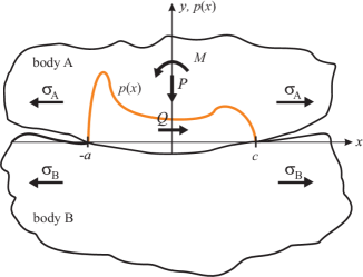
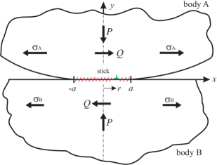
Static joints arise in many mechanical assemblies, and whilst the majority conform, a number of heavily loaded contacts have rounded edges. Examples include swashplate assemblies in helicopter rotor heads, dovetail roots in gas turbine fan blades, and in the locking segments used to fasten risers to well heads in subsea installations. These contacts invariably suffer complicated load histories and, as they are ‘incomplete’ in character the contact pressure falls smoothly to zero at the edges, so that they are prone to local slip. In fact, unless very special loading trajectories are followed, there will inevitably be some periods of slip with attendant fretting damage. Although some incomplete contacts which nearly conform must be modelled using elasticity formulations for the particular domain shape corresponding to their form (e.g. disk, anti-disk) the majority may adequately be represented using half-plane formulations [1]. The ‘core’ of the problem is represented by the idealised half-plane problem, Figure 1, and in this we can identify five load quantities which are relevant to the fretting fatigue problem, and all of which may be functions of time. There are; the normal load, , shear force, , moment, , and differential bulk tension arising from tensions developing in each body, .
If the contacting components are made from the same material the contacts are ‘uncoupled’ in character so that the normal contact problem may be solved first and then attention given to the effects of shear tractions which will have no influence on the normal solution.
Here, we will first review the historical solutions where the normal load is held constant, and then examine in more detail recent solutions which permit both more general forms of loading to be handled (including a rocking moment and differential bulk tension) and more general loading histories to be tracked out. The majority of solutions employ a method in which the shear traction distribution is viewed as the sum of that due to sliding, together with a corrective term, but progress has also been made with an alternative form in which a correction is made to the fully-stuck solution.
2 Constant Normal Load Problems
The earliest and best known normal contact solution was that found by Hertz, i.e. where the contacting bodies have second order (strictly parabolic but usual interpreted as circular arc) profiles [2], so it is natural that the first partial slip contact solutions were associated with the same geometry. The first solution, for a monotonically increasing shear force, was found by Cattaneo [3], and, apparently unaware of this solution, Mindlin [4] developed the same solution and went on to look at unloading and reloading problems [5], [6]. These were the only significant solutions for some time, and then Nowell and Hills [7] looked at what happened when a bulk tension was simultaneously exerted in one body as the shear force was gradually increased. Note that, while the application of an increasing shear force induces slip zones of the same sign at each edge of the contact, a tension induces slip of opposite sign and hence, when the two are exerted simultaneously, one slip zone will be bigger relative to the ‘no bulk tension’ case whilst the other will be smaller and, in the case of large tension may actually slip in the opposite direction. The next breakthrough came with the near simultaneous discovery by Jäger [8] and Ciavarella [9] that, just as the ‘corrective’ shear traction was a scaled form of the sliding shear traction for the Hertz case, the same geometric similarity applies whatever the form of the contact, and it worthwhile understanding the proof of this principle.
2.1 Jäger-Ciavarella Principle
It is assumed that the reader is familiar with the basic integral equations relating surface slope and surface strains to the surface tractions present on the surface of a half-plane. For a full explanation of these and their derivation see [10]. Although it is not a necessary condition in the first part of the calculation, it is very much easier to follow if we assume that the contact is symmetrical in . This ensures that the stick zone is centrally positioned, and only its extent needs to be found. If the relative profile of two elastically similar half-planes, each subject to a pressure over the contact length [], is such that their relative slope, , the following integral equation defines the implied contact pressure
| (1) |
where is Young’s modulus and is Poisson’s ratio and plane strain conditions obtain. For details of the inversion see Barber [10] or Hills et al. [11]. When once the contact pressure is known the size of the contact may be found from overall normal equilibrium, that is
| (2) |
As the contact is formed surface particles will displace laterally but, because the contact pressure is mutual and the materials are elastically similar, the displacement is the same in each body so that here is no difference in surface strain, and no shear tractions arise. A vanishingly small coefficient of friction is sufficient to inhibit all slip. Note that this would not be the case if a shear force were gradually exerted as the normal load was increased, see .
Here, we subsequently apply a monotonically increasing shear force so that slip starts at the edges where the contact pressure goes to zero. Suppose that the stick region has contracted to the interval []. For stick to be maintained in this region the differential strains parallel with the surface must vanish so that
| (3) |
Figure 2 shows the shear tractions, , and relative surface strains, .
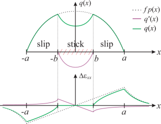
The shear traction, , is limited by the coefficient of friction in the outer slip regions
| (4) |
where is the coefficient of friction. The relative strain, , associated with a shear traction over the interval [] is given by
| (5) |
and here we write the shear traction as the sum of a contribution over the whole contact, limited by friction, together with an as yet unknown second ‘corrective’ term, , over the stick interval, giving
| (6) |
But we know that within the interval , so that
| (7) |
Now compare the first integral with that arising in the solution for the normal problem, given in equation (1). Note also that which means that we can re-write the integral equation for the corrective term in the form
| (8) |
Now, we see that the integral equation for the corrective term and the integral equation for a normal contact are very similar in form, differing only in the interval over which they are evaluated. It follows immediately that the form of the corrective shear traction must be similar to that for the pressure distribution, but appropriate to a lower load, which we denote . From equilibrium considerations we see that , and further
| (9) |
This is the very simple result needed. We will also be employing it, in extended forms, for more complicated problems in a later section. To do this, it is helpful to re-cast the problem in a contracted notation developed by Barber [12]. Suppose we denote the contact pressure distribution, for whatever geometry of problem we have under consideration, and when the applied load is by . Then, in the sequential loading problem just described, the partial slip shear traction distribution might be written as
| (10) |
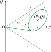
where the connection with the previous notation is . This loading history is conveniently displayed on a - plot where time tracks out a loading trajectory, Figure 3 a), and it should be noted that point is a point on the previous loading trajectory, here given by
| (11) |
and the stick zone half-width, , is given by .
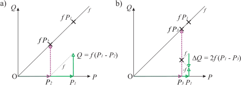
However, this tells only part of the story because, in the majority of problems, the shear force varies periodically. Upon an infinitesimal reduction in shear force stick ensues everywhere, and then a further reduction leads to zones of reverse slip developing. For a full description of the unloading problem see [5] and [12], but let us suppose that the greatest reduction in shear force from its maximum value is , which therefore denotes its range. Then the steady state sick zone half width, , is , where
| (12) |
see Figure 3 b). So, the steady state (or ‘permanent’) stick zone is greater than the initial one, , and this represents the phenomenon of ‘shaking down’, that is the self-development of locked in slip displacements (and hence shear tractions) which tends to reduce the tendency to slip. We note that the permanent stick zone size depends on the range of shear stress only and is independent of its mean value.
When a bulk stress is present varying in phase with the shear load, the position of the permanent stick zone, at least, will be affected. It has been shown by Andresen [13] that for a Hertzian contact subject to a shear force together with moderate bulk tension two explicit equations for extent, and eccentricity, , of the permanent stick zone can be established
| (13) |
and
| (14) |
In we will address in-phase steady-state solutions on a more general level.
3 Varying Normal Load Problems
Suppose that we have a motor, as depicted in Figure 4, whose shaft carries an eccentric weight, and that the motor is supported on contacts which may be idealised using half-plane principles.
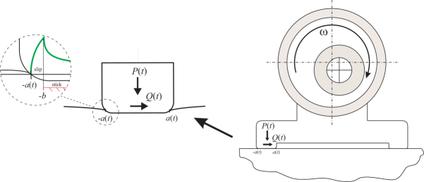
As the shaft rotates both the normal and shear forces on the contact will change, so that a loop is tracked out in - space of the form
| (15) |
| (16) |
where is the angular speed of the shaft and in the example given the phase shift, is . and are the mean values of the load and and are the respective normal and shear load amplitudes. Major progress in solving problems of this type, and where the intention was to track out the full behaviour as a function of time, was made in [12]. As before, the stick zone was symmetrically positioned and only its extent as a function of time was to be found.
When the normal load on a half-plane contact also varies with time, it is no longer the case that there must, necessarily, be slip at each time step. If the contact currently has a half-width, , and the load is increased by , the contact pressure will change by
| (17) |
Similarly, if the shear force is increased by the shear traction distribution will change by
| (18) |
so that the contact will remain adhered provided that
| (19) |
This result follows directly from the analogy between the Green’s functions for normal and shear loading. The question we now ask is ‘How does the shear traction change when we move between two points () on the loading trajectory when, at all intermediate points, the inequality given in equation (19) holds?’ The answer again comes from the analogy between the normal and shear components of loading, and is
| (20) |
where . In particular, point might be the start of loading. Note that, in this process, we are locking in shear traction and attendant slip displacement. This is one useful major new result. The second is the observation that, when a region of frictional slip is developing, provided that the quantities are interpreted correctly, the superposition idea of the Jäger-Ciavarella theorem continues to hold when the normal load is changing. So if we are at point ( during steady-state loading on the trajectory, the superposition (with a minus sign) of a corrective shear traction from some earlier point ( would ensure stick over the half width . The point is located by the imposition of tangential equilibrium, and gives
| (21) |
It is therefore found by drawing a line of gradient on the diagram and finding where the line intersects the loading curve. From these two principles a complete picture of the evolving stick-slip pattern, and the shear traction distribution can be tracked out [12], [14]. Note that, after the first cycle of loading the shear traction distribution changes from the initial one to a steady state distribution, and this modifies the form of the construction needed. The original papers should be studied for details, but one thing which emerges is that the size of the steady state permanent stick region, is found by drawing lines of gradient which are tangential to the envelope of loading, and these define a point , as shown in Figure 5.
Progress was also made on the problem of varying normal and bulk load alone, so that the slip zones are inherently antisymmetric but equal in size and magnitude, provided, again, that the contact itself is symmetrical [15]. But, there seemed little hope of being able to extend the idea of the Jäger-Ciavarella theorem to the case where both shear force and large bulk tension were present and varying in a complicated way, where large bulk tension means that the direction of slip is opposing at the ends of the contact. Thus, there has been no development of the method, in this form, for the cases of either (a) large bulk tension and shear force present, or (b) when the contact is not symmetrical, either because the indenter itself is not symmetrical or because there is a moment present.
4 Solutions on the Basis of Full Stick
All of the solutions presented above hinge on the superposition of the sliding shear traction distribution and a corrective shear in the stick region, i.e. of the two mixed boundary conditions to be enforced that in the slip region is automatically ensured whilst that in the stick region, which might more generally be thought of as ensuring that any locked-in surface strains are preserved, is found as a secondary consideration.
In this section we explore the possibility of starting off with a solution which is fully stuck (and which may or may not include a locked-in displacement), and then adding a perturbation to permit slip to establish itself. The kernel for this solution, therefore, is not the solution for a line force on a half-plane, but that for an edge dislocation, present on the interface line between two half-planes in glancing contact and traction-free outside the region of contact (which we will take as ), but bonded together within it, Figure 6. Two break-throughs were needed for this to be a possibility - one was obtaining the solution for a glide dislocation in the domain described and the second was devising an inversion procedure for a Cauchy integral equation imposed over two regions (the two slip zones), and these are described in the following articles by Hills et al. [16] and Moore et al. [17].
An edge dislocation, glide in character and therefore having Burgers vector installed at point , along the line defining the interface between two half-planes adhered together over the interval [] induces no direct traction along the interface but a shear traction given by
| (22) |
under plane strain conditions. This has the anticipated properties; there is a -like singular behaviour as the observation point approaches the dislocation , and the traction also becomes singular in an manner when the ends of the interval are approached.
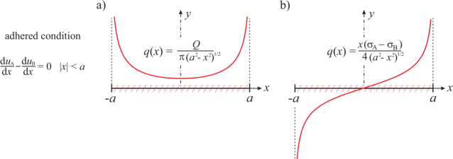
As a educational example, consider the sequentially loaded problem, where the normal load is applied first and then a shear force, is gradually exerted. If the contact is fully stuck the locked in strain difference is, here, zero throughout, i.e. . The shear traction induced along the contact, as shown in Figure 7 a), , will be singular at the edges. Equally, if tensions, , are developed in each body as shown in Figure 6 the shear tractions arising will be as shown in Figure 7 b). Combined, the fully stuck shear tractions are given by
| (23) |
Suppose that there is a slip zone attached to the left hand edge, stretching from and a slip zone attached to the right hand edge, stretching from . We therefore need to distribute glide dislocation over these intervals, and the dislocation density, represents the difference in surface strains. The corrective traction induced, , is given by
| (24) |
for . Note that, within the stick region () both integrals should be interpreted in a regular sense. In the left hand slip region,[, the first integral, only, is Cauchy and in the right hand slip region, [], the second integral, only, is Cauchy.
Now, the sign of slip depends on the relative magnitude of the shear force and bulk tension; if the shear force is large the slip zones will be of the same sign whereas if the bulk tension dominates they will be of opposite sign, but, in either case, we may write
| (25) |
The details of the integral equations and their inversion are given in the original papers cited, and a complementary solution for the normal contact problem itself, found using dislocations rather than a line for as the kernel, is given in [18].
5 Further Generalisation and the Steady State
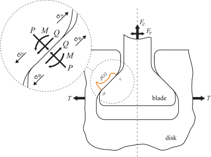
The formulations described in , may be used, in principle, to track out transient problems on a marching-in-time basis, with and without a phase shift, although the technique described in is incapable of handling the simultaneous presence of a shear force and bulk tension. The method outlined in has greater generality but it requires a numerical implementation when there is a phase shift, for example. There is also one feature of many contacts which is absent from the solutions treated so far, and this is the presence of a moment. A frequently occurring geometry in practice is, for example, the fan blade dovetail root contact referred to in the introduction, Figure 8. The blade might be subject to a centrifugal, , and vibration load, , and the disk experiences an expansion force, . This type of contact may be approximated by a punch having a flat base but rounded corners, and which is therefore capable of sustaining a moment, , unlike a Hertzian contact.
Therefore, the most general loading of a half-plane contact is represented by the four variables . It is noteworthy that the tendency to slide is independent of , i.e. it depends on the ratio alone. Also, the normal load problem depends only on the pair , and is independent of the other two quantities. And, when once the normal problem is solved, the partial slip problem depends only on , , i.e. because the normal and tangential problem are uncoupled if the contacting bodies are elastically similar and the effect of geometric coupling is negligible, these last two quantities do not feed back into the normal load problem.
Earlier, we gave the condition for no slip where the contact was loaded by the pair () alone, equation (21). Suppose that we have a frictional contact whose instantaneous half-width is , and we make a small change, , in normal load together with a small change in moment, . If at the same time there are small changes in shear force, and differential bulk tension, , the inequality for no slip is
| (26) |
where we choose the upper sign when considering the left hand side (LHS) of the contact and the lower sign when considering the right hand side (RHS) of the contact. The necessary condition for no slip is that the inequality holds at both sides of the contact.
If we return, again, to the practical problem just mentioned we note that there are two loads in the system which are substantially constant, varying only occasionally (the centrifugal load, and expansion force, ). Although these will excite all four components of contact load, they are taken to a mean value which we denote by the addition of a subscript, . Also, there is a second source of loading on the assembly - vibration loads, - and these, too exert all four contact loads. But, because it is a solitary load which excites those changes, they all occur in phase, which makes the problem rather easier to solve than the shaft with an eccentric weight referred to in , because there are no phase shifts, and all four quantities change together. Thus, the problem we have to solve for is one in which the quantities move along a straight line segment in --- load space during the steady-state. The condition for the assembly to become locked (even if the transient movement cause by the primary load violates inequality (26) is this same one but where the infinitesimal changes are replaced by the finite ranges of the same quantities in the steady state. When the inequality is violated, there will be some steady state slip. And, in the problems cited, there will be usually many tens of thousand of ‘steady state’ cycles for each change in the ‘mean’ load. So, the most general, transient behaviour which we have, so far, studied may not be particularly relevant, and it is the steady state response (established after a single cycle) which really matters, and this is relatively easy to find. It is difficult to visualise the problem in an abstract four-dimensional load space. Therefore, it is valuable to visualise the history of loading in the three-dimensional load space depicted in Figure 9, ignoring the bulk tension, .
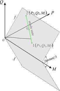
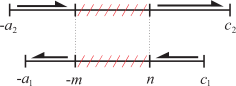
What we need to do is to write down the state of the contact at the two end points of the steady-state cycle - in the case of the strain/shear traction equation, immediately before the end point is reached, when the slip zones are at their maximum extent. We will assume that, in the load space described, the coordinates are given by (), where , and the first location corresponds to, for example, , and the second point to, for example, . Figure 10 is a schematic of the size and position of the contact at these extremes, together with an impression of the permanent stick zone. We shall assume that the bulk load is insufficient to reverse the direction of slip at the end of the contact where it is subtractive.
Consider, first, the normal loading problem. Although this is not a necessary step, we will assume that the contact itself is symmetrical in form, so that is strictly odd, but permit there also to be a rotation, , which varies with the applied moment. The contact is now assumed to occupy the interval [] and so a modified form of the integral equation given at the beginning of , equation (1), is needed. At point in the loading cycle (), the relative slope of the half-plane surfaces, , is given by
| (27) |
and normal and rotational equilibrium are imposed by setting
| (28) | ||||
| (29) |
We turn, now, to the ‘tangential’ integral equation and write that the difference in surface strains at any location in the surface, at load state ‘1’ is given by
| (30) |
where permanent stick is present over the interval []. At load point 2 we write a similar expression, but with the sign of the overall sliding shear traction reversed, so as to give the correct sign of shear traction in the end slip regions, as
| (31) |
The permanent stick zone must be unique, and is that present at each of these points, in order to ensure continuity of material, so that the locked-in strain within this region is preserved, i.e.
| (32) |
In the permanent stick zone, , these equations become
| (33) |
where . Since use may be made of the ‘normal’ solution, in a manner similar to that use by Jäger and Ciavarella, and we may write
| (34) |
where . Note that the left hand side consists of only two terms - the gradient of the surface as it appears in the ‘normal’ integral equation, and a constant. This means that solution is very straightforward, and the original papers by Andresen et al. [13] and [19] should be consulted for full details. The only additional elements needed are the range of shear force, , which is given by
| (35) |
where is the mean normal load, and
| (36) |
6 Conclusions
We have reviewed the current state of understanding of partial slip half-plane contact problems, starting from the first steps made by Cattaneo over eighty years ago. The concepts given have not been attached to a particular geometry although inevitably the more complicated the indenter shape the more taxing the algebra is when it comes to implementation.
A full description of the partial slip solution means that we must know, first, the evolving stick pattern during the load cycle. The locked in shear distribution within this permanent stick zone has no practical bearing on the solution, and this means that, in periodic problems the transient loading from an unloaded state, which affects precisely just this locked in shear (and attendant slip displacement) does not have any practical effect on the steady state solution. A complete solution requires other information - in particular the slip displacement - but this can be evaluated when once the stick zone is established, by various means. And, when once that is done, other derivative information - the pointwise frictional energy expenditure, total frictional damping energy, surface stress etc. can all be found quite easily.
The paper distinguishes clearly between tracking out problems in a marching-in-time sense, including transient conditions, and separates these from the simpler but often more important steady state response. It looks at alternative methods of formulation based on perturbations of the full-stick solution, using dislocations as the kernel. The question of asymptotic representations of the slip zone conditions, which are of practical interest in matching test conditions, is specifically excluded.
Acknowledgements
This project has received funding from the European Union’s Horizon 2020 research and innovation programme under the Marie Sklodowska-Curie agreement No 721865. David Hills thanks Rolls-Royce plc and the EPSRC for the support under the Prosperity Partnership Grant ’Cornerstone: Mechanical Engineering Science to Enable Aero Propulsion Futures’, Grant Ref: EP/R004951/1.
References
- [1] J. Barber, Contact Mechanics, Springer, 2018.
- [2] H. Hertz, Über die Berührung fester elastischer Körper, Journal für die reine und angewandte Mathematik 92 (1881) 156–171.
- [3] C. Cattaneo, Sul contato di due corpo elastici, Atti Accad. Naz. Lincei, Cl. Sci. Fis., Mat. Nat., Rend. 27 (1938) 342–348, 434–436, 474–478.
- [4] R. Mindlin, Compliance of elastic bodies in contact, AASME Trans. Jnl. Appl. Mech. 16 (1949) 259–268.
- [5] R. Mindlin, W. Mason, T. Osmer, H. Deresiewicz, Effect of an oscillating tangential force on the contact surfaces of elastic spheres, Proc. First Nat. Congress of Applied Mechanics (1951) 203–208.
- [6] R. Mindlin, H. Deresiewicz, Elastic spheres in contact under varying oblique forces, J. of Applied Mechanics 20 (1953) 327–344.
- [7] D. Hills, D. Nowell, Mechanics of fretting fatigue tests, Int. Jnl. Mech. Sci. 29 (1987) 355–365.
- [8] J. Jäger, Ein neues Prinzip der Kontaktmechnik, ZAMM 77, Issue S1 (1997) 143–144.
- [9] M. Ciavarella, The generalised cattaneo partial slip plane contact problem, part i theory, part ii examples, Int. Jnl. Solids Struct. 35 (1998) 2349–2378.
- [10] J. Barber, Elasticity (third edition), Springer, 2010.
- [11] D. Hills, D. Nowell, A. Sackfield, Mechanics of Elastic Contacts, Butterworth-Heinemann, 1993.
- [12] J. Barber, M. Davies, D. Hills, Frictional elastic contact with periodic loading, Int. Jnl. Solids Struct. 48 (2011) 2041–2047.
- [13] H. Andresen, D. Hills, J. Barber, J. Vázquez, Frictional half-plane contact problems subject to alternating normal and shear loads and tension in the steady state, Int. Jnl. Solids Struct. 168 (2019) 166–171.
- [14] D. Hills, M. Davies, J. Barber, An incremental formulation for half-plane contact problems subject to varying normal load, shear and tension, J. Strain Analysis 46 (2011) 436–443.
- [15] R. Ramesh, J. Barber, D. Hills, Plane incomplete contact problems subject to bulk stress with a varying normal load, Int. J. Mech. Sci. 122 (2017) 228–234.
- [16] D. Hills, R. Ramesh, J. Barber, M. Moore, Methods to solve half-plane partial slip contact problems, Int. Jnl. Solids Struct. 155 (2018) 155–159.
- [17] M. R. Moore, R. Ramesh, D. Hills, J. Barber, Half-plane partial slip contact problems with a constant normal load subject to a shear force and a differential bulk tension, Jnl. Mech. Phys. Solids 118 (2018) 245–253.
- [18] M. R. Moore, D. Hills, Solution of half-plane contact problems by distributing climb dislocations, Int. Jnl. Solids Struct. 147 (2018) 61–66.
- [19] H. Andresen, D. Hills, J. Barber, J. Vázquez, Steady state cyclic behaviour of a half-plane contact in partial slip subject to varying normal load, moment, shear load, and moderate differential bulk tension, Int. Jnl. Solids Struct. 182-183 (2020) 156–161.