Optimal coupling of HoW10 molecular magnets to superconducting circuits near spin clock transitions
Abstract
A central goal in quantum technologies is to maximize T2, where stands for the coupling of a qubit to control and readout signals and T2 is the qubit’s coherence time. This is challenging, as increasing (e.g. by coupling the qubit more strongly to external stimuli) often leads to deleterious effects on T2. Here, we study the coupling of pure and magnetically diluted crystals of HoW10 magnetic clusters to microwave superconducting coplanar waveguides. Absorption lines give a broadband picture of the magnetic energy level scheme and, in particular, confirm the existence of level anticrossings at equidistant magnetic fields determined by the combination of crystal field and hyperfine interactions. Such ’spin clock transitions’ are known to shield the electronic spins against magnetic field fluctuations. The analysis of the microwave transmission shows that the spin-photon coupling becomes also maximum at these transitions. The results show that engineering spin-clock states of molecular systems offers a promising strategy to combine sizeable spin-photon interactions with a sufficient isolation from unwanted magnetic noise sources.
I Introduction
Spins embedded in solid hosts are one of the simplest and most natural choices to realize qubits, the building blocks of quantum technologies.[1, 2] Their quantized spin projections can encode the qubit states whereas operations between them can be induced via the application of microwave radiation pulses, using well-established magnetic resonance protocols. Among the different candidates, chemically designed magnetic molecules stand out for several reasons.[3, 4] Besides being microscopic, thus reproducible and intrinsically quantum, they represent the smallest structure that remains tuneable. The ability to modify the relevant properties by adequately choosing the molecular composition and structure allows engineering the qubit spin states and energies.[5, 6] Even more, it enables scaling up computational resources within each molecule, e.g. by accommodating several different magnetic atoms in exquisitely defined coordinations [7, 8, 9, 10, 11] or by making use of multiple internal spin states.[12, 13, 14, 15]
This approach however faces the challenge of how to actually implement operations and read out the results in a realistic device and, even more, how to ’wire up’ different molecules into a scalable architecture. A promising technology is to exploit microwave photons in circuits, e.g. transmission lines for the control of spin operations and resonators for reading out the spin states and for introducing effective interactions.[16, 17, 18, 19, 20, 21] Working with high-spin molecules helps maximizing the spin-photon coupling, as required for such applications.[18] However, it also tends to enhance decoherence, as their interactions with fluctuating hyperfine and dipolar magnetic fields also become stronger.[22, 23]
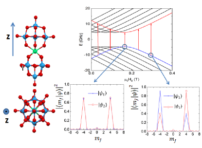
A general strategy to reconcile a high qubit density with sufficient isolation is to encode each qubit in states that are robust against the dominant noise sources.[24] This idea underlies the design of the trasmon superconducting qubit[25] and of several semiconducting quantum dot qubits.[26] In the case of spins, isolation from magnetic field fluctuations can be achieved by associating and to superpositions states that arise at avoided level crossings, or ’spin-clock’ transitions.[27, 28, 29] Such transitions have been observed in impurity dopants in semiconductors[29] and in crystals hosting lanthanide ions,[27, 28] and can arise from either significant off-diagonal anisotropy terms in non-Kramers electronic spins or from hyperfine couplings in electronuclear spin systems. They have also recently been studied in magnetic molecules.[6, 30, 31, 32, 33, 34] A paradigmatic example of the latter is provided by the sodium salt of the cluster [Ho(W5O18)2]9-,[35, 36] hereafter referred to as HoW10, which consists of a single Ho3+ ion encapsulated by polyoxometalate moieties (Fig. 1). Its fourfold coordination symmetry gives rise to fourth order off-diagonal terms in the spin Hamiltonian that strongly mix the projections of the ground electronic spin doublet. The large quantum tunneling gap GHz generated by such terms, combined with the hyperfine interaction with the spin of the Ho nucleus, gives rise to a set of level anti-crossings (see Fig. 1). Near each of them, the spin coherence time T2 is sharply enhanced [6] and the electron spin system effectively decouples from the nuclear spin. [37]
In this work, we explore the coupling of HoxY1-xW10
single crystals ( and ) to superconducting co-planar
waveguides. These experiments provide a direct method to
investigate in detail how the spin-photon coupling evolves as a
function of magnetic field, thus both near and far from the spin-clock transitions, and temperature. The manuscript is organized as follows. Section II provides details
on the preparation of
the samples, the design and fabrication of the devices and the
transmission measurements.
Section III describes results obtained under different
experimental conditions and discusses them with the help of input-output theory. The last
section IV is left for the conclusions.
II Experimental details
II.1 Sample preparation and characterization
The synthesis of HoxY1-xW10 crystals followed established protocols.[35] The samples were kept in their mother solution until a experiment had to be performed, in order to protect them from degradation. The samples were characterized by means of specific heat and magnetic measurements. The results agree with those reported previously [35] and therefore confirm that HoW10 clusters have an electronic spin ground state and a sizeable quantum tunneling gap .
II.2 Superconducting device design and fabrication
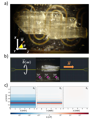
Two types of circuits hosting superconducting coplanar waveguides were employed in the microwave transmission experiments that form the core of this work. The first one consists of a m wide central transmission line separated from two ground planes by m wide gaps. It was fabricated by optical lithography of nm thick Nb films deposited by sputtering onto a single-crystalline sapphire substrate. The size of the central line and its meander shape were designed in order to match the dimensions (ca. mm3) of the HoW10 single crystals that were measured in experiments performed at K (Fig. 2a).
A second device was fabricated to optimize the coupling to the smaller size, magnetically diluted HoxY1-xW10 crystals employed in the very low-T experiments (Fig. 2b). It consists of a m wide straight transmission line, separated from the ground planes by m wide gaps in order to maintain a Ohm characteristic impedance. It was fabricated by maskless lithography and reactive ion etching techniques on a nm thick Nb film deposited by means of DC magnetron sputtering on a m thick silicon substrate. The native oxide of the silicon wafer was previously removed using a hydrofluoric acid bath. The base pressure prior to the deposition of Nb was better than Torr.
The magnetic field distribution generated by the microwave superconducting currents propagating via these transmission lines has been calculated using the electromagnetic simulation package SONNET [38] and finite element simulations. Results of these simulations are shown in Fig. 2c. The microwave magnetic field is confined in a plane perpendicular to the line. This information is relevant to prepare and interpret the transmission experiments, because resonant transitions between different spin states are only allowed if the microwave field has a non zero projection along the molecular magnetic anisotropy axis (see section III for details). Besides, its magnitude falls off quickly as one moves away from the line. This means that the experiments typically explore the coupling of a very small region of the crystal. Working with small crystals and sufficiently small lines, which becomes feasible at very low temperatures, helps to mitigate the effects of inhomogeneities associated with crystal twinning.
II.3 Microwave transmission experiments
The crystals were attached onto the transmission line with apiezon N grease. Microwave transmission experiments were performed by connecting the input and output ports of the chip to a vector network analyzer that measures the transmission coefficient for frequencies ranging between GHz and GHz. For experiments at K, the chips were submerged in the liquid Helium bath of a cryostat equipped with a T T T vector magnet. This set-up allows applying dc magnetic fields with amplitudes up to T along any arbitrary direction in the , , laboratory reference frame shown in Fig. 2a. In these experiments, was rotated within the plane of the device. Experiments were also performed at temperatures below K, from mK up to mK, in order to control and optimize the thermal polarization difference between the levels involved in each resonant transition, thus the spin-photon coupling. The chips were thermally anchored to the mixing chamber of a cryo-free dilution refrigerator, and placed at the centre of an axial T magnet ( was parallel to in this case, as shown in Fig. 2b). The transmission experiments were performed as described above, with the inclusion of a set of attenuators, for a total dB, in the input line and of a low noise cryogenic amplifier (gain dB) at the K stage in the output line.
In order to compensate for the decay of the waveguide transmission with increasing frequency and to enhance the contrast of those effects associated with its coupling to the spins, was normalized. For this, we compare transmission data measured at two different magnetic fields. [39] The normalized transmission at magnetic field and frequency is given by
| (1) |
where and is the transmission of the ’bare’ transmission line. In practice, is measured at a magnetic field for which all spin excitations lie outside the accessible frequency region. For smaller than the magnetic field width of a given spin transition, approximately corresponds to the derivative of the normalized transmission, similar to the signal detected in conventional Electron Paramagnetic Resonance (EPR) experiments. The actual transmission can also be obtained, by choosing a larger but at the cost of deteriorating the signal-to-noise ratio.
III Results
III.1 Broad-band spectroscopy: field-tuned clock transitions
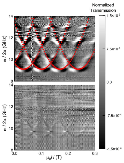
Figure 3 shows two-dimensional maps of the transmission through a m wide transmission line coupled to large pure (top panel) and magnetically dilute (bottom panel) crystals. These data were measured at K with the dc magnetic field applied along the axis. Because of the geometry of the line (see image in Fig. 2a and simulations in 2c), the microwave magnetic field felt by the crystal was mainly confined to the plane. The data neatly show changes in transmission associated with the resonant absorption of microwave photons by the HoW10 spins. Each of these resonances corresponds to an allowed transition between two states with a different electronic spin state and the same nuclear spin state, such as those marked by vertical arrows in Fig. 1. These resonance lines provide then a complete picture of the low-lying magnetic energy levels in HoW10. In particular, they show the presence of a finite gap GHz in the excitation spectrum at different avoided level crossings. The spectroscopic patterns of pure and magnetically diluted crystals agree, save for the narrower lines observed in the latter case and the difference in absorption intensities associated with the number of spins that effectively couple to the propagating photons in each case.
III.2 Numerical simulation of the transmission spectra
| (2) |
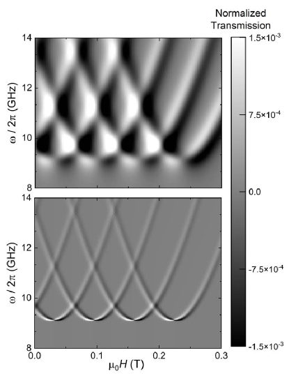
that includes four crystal field terms, the Zeeman interaction with the external magnetic field and the hyperfine interaction. The parameters , cm-1, cm-1, cm-1, cm-1, cm-1 have been determined from EPR experiments on magnetically diluted samples.[36, 6] It follows that the ground state corresponds to the doublet, split by tunneling terms (mainly the term) and by hyperfine interactions. Because of the very strong uniaxial magnetic anisotropy of HoW10, avoided level crossings occur at , with mT for the crossing of states with nuclear spin projection and , respectively. The only free parameter is then the orientation of the molecular easy axis with respect to the external magnetic field, which amounts to rescaling the magnetic field axis. As shown in Fig. 3, we find a good agreement with the same parameters given above. These results show that the concentrated crystals used in this work retain the same magnetic anisotropy and confirm that the strong spin tunneling, and the associated energy gap, are genuine properties of each molecule.
It is also possible to simulate the full transmission spectra. For this, we apply input-output theory to the interaction of microwave photons propagating via the transmission line with the electronic magnetic moments of the molecules. The complex transmission is then given by[40, 41]
| (3) |
where is the photon-induced transition rate between spin states , with energy , and , with energy , (see Fig. 1), is the spin line width and is the resonance frequency at the given magnetic field. The interaction constant parameterizes the spin photon coupling and is, therefore, our main interest in this work. Time dependent perturbation theory gives the following expression
| (4) |
where is a spin-photon coupling density, which depends on the mode density in the transmission line and on geometrical factors (mainly the number of spins, their location with respect to the circuit and the latter’s geometry), is the bosonic occupation number, is the thermal population difference between the two levels and is the partition function. Only the microwave field component parallel to the anisotropy axis contributes to the coupling, because for any superposition of states. This explains why is determined by the matrix element of .
We have performed numerical simulations of the normalized transmission amplitude based on Eqs. (1), (3) and (4) and the spin wave functions derived from the spin Hamiltonian (2). We approximate the spin-photon coupling density by the expression , valid in the limit of one-dimensional transmission lines.[42] Here, is an adjustable fitting parameter. The resonance line widths are of order MHz for both the pure and magnetically diluted crystals. Electron spin resonance experiments performed on Ho0.2Y0.8W10 show that T s at K. The homogeneous broadening MHz is therefore much smaller than the resonance width observed in experiments, suggesting that the latter is dominated by the inhomogeneous broadening. We recognize that there are multiple sources of line broadening,[6] which include dipole-dipole interactions between molecular spins and distributions in the orientations of the molecular axes and of their crystal field parameters (e.g. that gives rise to the tunnel splitting ).[36, 6] In the simulations shown in Fig. 4 their effect was introduced with gaussian field distributions having mT for and mT for . These parameters were chosen to give the best overall agreement with the experiments.
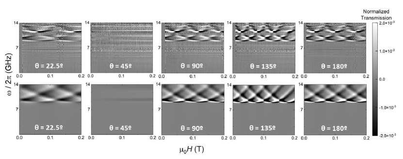
III.3 Dependence on magnetic field orientation
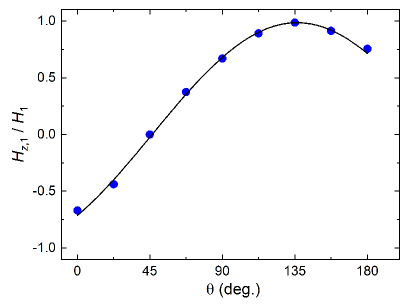
The experiments on the pure HoW10 crystal (Fig. 2a) were repeated for different orientations of in the plane of the chip. This geometry allows varying the angle between and the molecular anisotropy axis , while minimizing effects associated with the excitation and motion of superconducting vortices. The results are shown in Fig. 5. Clear changes in the absorption pattern are observed. They correspond to different magnetic field periodicities of the avoided level crossings. As we have mentioned above, these anticrossings are mainly determined by the condition , which requires reaching higher magnetic fields strengths the more deviates from the anisotropy axis. When the magnetic field forms an angle degrees with the and laboratory axes, the pattern disappears, showing that is then nearly orthogonal to . By contrast, the pattern period becomes minimum for degrees, showing that is then closest to within the plane. The dependence of the experimental on is shown in Fig. 6. Fitting these data allows estimating in situ the orientation of the magnetic anisotropy axis with respect to the crystal and to the laboratory reference frame. The results are compatible with pointing along the long molecular axis (Fig. 1).
Once the orientation of is set, the positions of the resonances and the full transmission spectra can be calculated for any magnetic field angle. The results, shown in Fig. 5, agree very well with the experimental ones. This agreement confirms the very strong uniaxial magnetic anisotropy of HoW10 and provides a basis to analyze how the spin photon coupling depends on temperature and magnetic field strength. Besides, it shows that generated by a straight transmission line (Fig. 2b and 2c), although perpendicular to the external , has a sizeable component along . Therefore, it should also provide a nonzero spin-photon coupling. This simpler geometry (Fig. 2b) was then adopted for experiments performed at very low temperatures, which are discussed in what follows.
III.4 Broad band spectroscopy below 1 K: temperature dependence of the spin-photon coupling
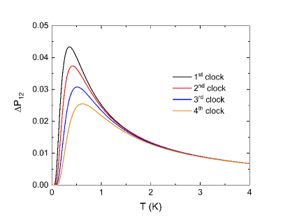
The relative populations of the spin levels involved in a resonant transition influence the effective spin-photon coupling (see Eq. (4)). In equilibrium, this introduces a temperature dependence through the polarization parameter , which is plotted in Fig. 7. Decreasing leads to a larger polarization provided that remains sufficiently high with respect to and to the hyperfine splitting of each electronic level. The fact that spin-clock transitions in HoW10 involve two excited levels gives rise to a maximum followed by a rapid drop in polarization.
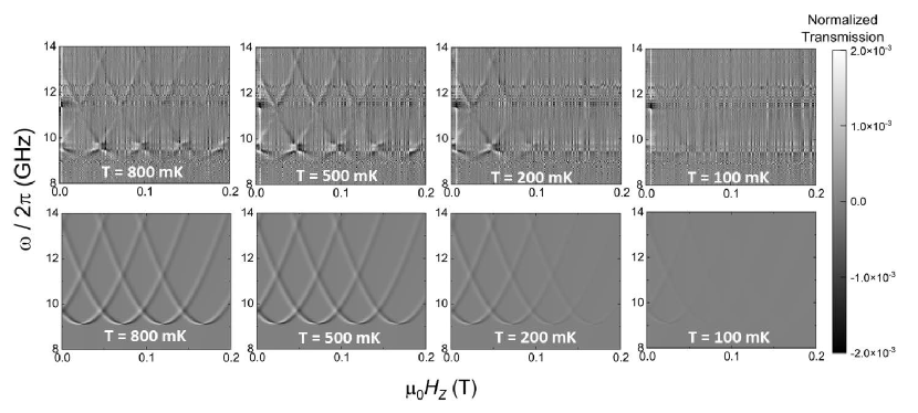
This behaviour is confirmed by experiments performed with the circuit shown in Fig. 2b on a Ho0.2Y0.8W30 single crystal. Transmission spectra measured at different temperatures are shown in Fig. 8. The relative intensities of the four clock transitions remain comparable to each other until, on cooling below K, they begin to gradually fade away from right () to left (). Numerical calculations based on Eqs. (3) and (4) are also shown in Fig. 8. They agree with this behaviour. For this reason, we have chosen the data measured at K to study the magnetic field dependence of the spin-photon coupling.
III.5 Magnetic field dependence of the spin-photon coupling near spin-clock transitions
Whereas the positions of the resonance lines give access to the energy level scheme, their intensities provide information on the wavefunctions of the involved states. An important advantage of working with open waveguides is that both frequency and magnetic field can be varied independently of each other. It is therefore possible to monitor how the absorption intensity varies as a function of .
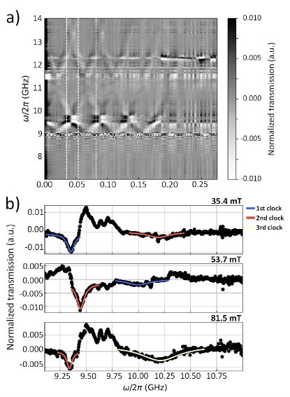
Figure 9a shows a plot of normalized transmission data measured at K. As discussed above (see also Fig. 7), this temperature provides a good polarization for all relevant spin transitions. The normalization (Eq. (1)) was performed by subtracting data measured at magnetic fields separated by mT. The minima in the normalized transmission traces (Fig. 9b) provide then the full absorption resonance lines at the given fields, whereas the maxima correspond to (minus) the absorption at . Notice that the relative positions of minima and maxima reflect the magnetic field slope of the HoW10 transition frequencies. Spurious resonant modes of the transmission line lead to additional transmission ’bumps’ that form horizontal lines in the plot. In the analysis that follows, we have only considered data measured sufficiently far from such modes.
We observe that the visibility, defined as the minimum of each transmission dip, becomes enhanced on approaching the avoided level crossings. This phenomenon is visible in all experiments (see e.g. Fig. 3). It can be analyzed in more detail by looking at the frequency dependence of the transmission measured at fixed magnetic fields (Fig. 9b). Let’s consider, for instance, the first transition, that links states with nuclear spin projection . The maximum absorption measured near the anticrossing, at mT and GHz, is approximately ten times larger than that measured away from it, at mT and GHz. The same comparison can be made, at constant , between the intensities of different transitions that lie close or far from their respective avoided level crossings, e.g. the first and second transitions at mT (Fig. 9b).
In order to get a more quantitative characterization, fits of all absorption lines have been performed with Eq. (3). The fitting parameters were the spin-photon coupling and the line width , which here parameterizes the dominant inhomogeneous broadening. The results are shown in Fig. 10. The increasing difficulty in properly normalizing the transmission plus the presence of a spurious mode near GHz prevents getting data right at the clock transitions. Yet, in spite of the experimental limitations, the results show that becomes maximum at the four avoided level crossings, as can be seen in Fig. 10. Also, the linewidth seems to become larger on moving away from the anticrossings.
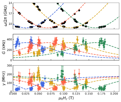
This result admits a qualitative interpretation based on Eq. (4) and on the nature of the spin transitions in HoW10 (see Fig. 1). The spin photon coupling is largely determined by the matrix element of between states with the same nuclear spin projections. The relevant subspace reduces then to a two-level tunneling system for which , where . The matrix element then inherits, although inverted, the field dependence of the level anticrossing. It reaches a maximum value when the two levels come closest to each other () and their wave functions become maximally delocalized between opposite angular momentum projections. Then, it decreases as the field moves away from . Calculations performed inserting this simple expression for the matrix element into Eq. (4) reproduce quite well the experimental results, as shown in Fig. 10. The maximum is enhanced in systems with a high spin ground state, as it is often the case with lanthanide ions and with HoW10 in particular, for which .
Concerning the linewidth, it is expected that decreases near the clock transitions. The electronic spins become then less sensitive to magnetic fields, thus also to perturbations arising from dipolar interactions with neighbour molecules [32], hyperfine couplings to nuclear spins [37] and the misalignment of the molecular axes. The experimental results, shown in the botom panel of Fig. 10, confirm that spin resonances tend to narrow near the avoided level crossings. This effect can be approximately described by the expression ,[43, 6] where the second term is proportional to the effective magnetic moment, which tends to vanish near a clock transition and therefore suppress the effect of bias field broadening, and the first accounts for other sources of broadening. A reasonably good fit is obtained for mT and MHz. The latter value turns out to be smaller than the level broadening, of about MHz, estimated from EPR experiments performed on diluted crystals and that was associated with a distribution in .[6] The reason behind this discrepancy is not clear to us, but it might arise from a combination of the especial conditions of our experiments, which are sensitive to a tiny region within a tiny crystal, and the origin of the anisotropy parameter distribution. The results suggest that the line broadening we observe is dominated by environmental magnetic fields and that their influence is reduced near the level anticrossings.
IV Conclusions
We have explored the coupling of HoW10 molecular magnets to superconducting transmission waveguides. The results provide a broandband picture of the energy spectrum associated to the ground states. They confirm the existence of avoided level crossings, or spin clock transitions, at equispaced magnetic field values, determined by the magnetic anisotropy and hyperfine interactions. Near each anticrossing, we find that the spin-photon coupling becomes maximum, likely reflecting the maximum overlap between the two spin wavefunctions involved in the resonant transition. This reveals a quite unique property of spin-clock transitions. Not only do they shield spin states against magnetic field fluctuations, which leads to longer spin coherence times T2,[6] but they also optimize their coupling to external radiation fields. Since , the latter effect is enhanced in qubits that, like HoW10, are characterized by a large effective ground state spin. This property makes spin clock transitions in artificial magnetic molecules highly promising for developing fast and robust spin qubits. The limitation imposed by the difficulty of tuning with a magnetic field can be compensated by exploiting electric fields, whose effect becomes maximum near the anticrossings.[44]
The experimental scheme used in this work provides also the standard tool to control spin qubits on a chip, as has been shown by experiments performed on NV- centres in diamond [45] and impurity spins in silicon.[46] Our results show a simple method to maximize the Rabi frequencies of single qubit operations on high-spin systems with suitable magnetic anisotropies. Besides, this scheme can be easily integrated with circuit QED architectures, e.g. with the application of superconducting resonators to read-out the spin states.[19] The enhancement of the spin-photon coupling found here should also lead to larger dispersive shifts, thus improve the visibility of different spin states.[47] This is especially relevant when dealing with molecular spin qudits, e.g. those based on Gd3+ ions.[12] Even though Gd3+ is a Kramers ion, the combination of non-diagonal magnetic anisotropy terms and adequately oriented external magnetic fields also leads to avoided level crossings in these systems. Exploiting the enhanced spin-photon coupling near them might then allow reaching the high cooperativity regime even with non too diluted crystals, and therefore provide a suitable platform for proof-of-concept implementations of qudit based algorithms.[48, 49]
Acknowledgments
This work has received support from grants RTI2018-096075-A-C21, PID2019-105552RB-C41, PID2019-105552RB-C44, P2018/NMT-4291 TEC2SPACE-CM, TED2021-131447B-C21, TED2021-131447B-C22, CEX2019-000919-M and CEX2020-001039-S, funded by MCIN/AEI/10.13039/501100011033, ERDF ’A way of making Europe’ and ESF ’Investing in your future’ and from the Gobierno de Aragón grant E09-17R-Q-MAD. We also acknowledge funding from the European Union Horizon 2020 research and innovation programme through FET-OPEN grant FATMOLS-No862893, ERC advanced grant Mol-2D-No788222, ERC consolidator grant DECRESIM-No647301 and HORIZON-MSCA-2021 grant HyQuArch-No101064707. This study forms also part of the Advanced Materials and Quantum Communication programmes, supported by MCIN with funding from European Union NextGenerationEU (PRTR-C17.I1), by Gobierno de Aragón, by Generalitat Valenciana and by CSIC (PTI001). SH acknowledges support of the US Department of Energy (DE-SC0020260). Work done at the National High Magnetic Field Laboratory is supported by the US National Science Foundation (DMR-1644779 and DMR-2128556) and the State of Florida.
References
- Bertaina et al. [2007] S. Bertaina, S. Gambarelli, A. Tkachuk, I. N. Kurkin, B. Malkin, A. Stepanov, and B. Barbara, Nat. Nanotechnol. 2, 39 (2007).
- Awschalom et al. [2013] D. D. Awschalom, L. C. Bassett, A. S. Dzurak, E. L. Hu, and J. R. Petta, Science 339, 1174 (2013).
- Gaita-Ariño et al. [2019] A. Gaita-Ariño, F. Luis, S. Hill, and E. Coronado, Nat. Chem. 11, 301 (2019).
- Carretta et al. [2021] S. Carretta, D. Zueco, A. Chiesa, A. Gómez-León, and F. Luis, Appl. Phys. Lett. 118, 240501 (2021).
- Martínez-Pérez et al. [2012] M. J. Martínez-Pérez, S. Cardona-Serra, C. Schlegel, F. Moro, P. J. Alonso, H. Prima-García, J. M. Clemente-Juan, M. Evangelisti, A. Gaita-Ariño, J. Sesé, J. van Slageren, E. Coronado, and F. Luis, Phys. Rev. Lett. 108, 247213 (2012).
- Shiddiq et al. [2016] M. Shiddiq, D. Komijani, Y. Duan, A. Gaita-Ariño, E. Coronado, and S. Hill, Nature 531, 348 (2016).
- Luis et al. [2011] F. Luis, A. Repollés, M. J. Martínez-Pérez, D. Aguilà, O. Roubeau, D. Zueco, P. J. Alonso, M. Evangelisti, A. Camón, J. Sesé, L. A. Barrios, and G. Aromí, Phys. Rev. Lett. 107, 117203 (2011).
- Aromí et al. [2012] G. Aromí, D. Aguilà, P. Gamez, F. Luis, and O. Roubeau, Chem. Soc. Rev. 41, 537 (2012).
- Aguilà et al. [2014] D. Aguilà, L. A. Barrios, V. Velasco, O. Roubeau, A. Repollés, P. J. Alonso, J. Sesé, S. J. Teat, F. Luis, and G. Aromí, J. Am. Chem. Soc. 136, 14215 (2014).
- Ferrando-Soria et al. [2016] J. Ferrando-Soria, E. Moreno-Pineda, A. Chiesa, A. Fernández, S. A. Magee, S. Carretta, P. Santini, I. J. Vitorica-Yrezabal, F. Tuna, G. A. Timco, E. J. L. McInnes, and R. E. P. Winpenny, Nat. Commun. 7, 11377 (2016).
- Fernández et al. [2016] A. Fernández, J. Ferrando-Soria, E. Moreno-Pineda, F. Tuna, I. J. Vitorica-Yrezabal, C. Knappke, J. Ujma, C. A. Muryn, G. A. Timco, P. E. Barran, A. Ardavan, and R. E. P. Winpenny, Nat. Commun. 7, 10240 (2016).
- Jenkins et al. [2017] M. D. Jenkins, Y. Duan, B. Diosdao, J. J. García-Ripoll, A. Gaita-Ariño, C. Giménez-Saiz, P. J. Alonso, E. Coronado, and F. Luis, Phys. Rev. B 95, 064423 (2017).
- Godfrin et al. [2017] C. Godfrin, A. Ferhat, R. Ballou, S. Klyatskaya, M. Ruben, W. Wernsdorfer, and F. Balestro, Phys. Rev. Lett. 119, 187702 (2017).
- Moreno-Pineda et al. [2018] E. Moreno-Pineda, C. Godfrin, F. Balestro, W. Wernsdorfer, and M. Ruben, Chem. Soc. Rev. 47, 501 (2018).
- Hussain et al. [2018] R. Hussain, G. Allodi, A. Chiesa, E. Garlatti, D. Mitcov, A. Konstantatos, K. S. Pedersen, R. De Renzi, S. Piligkos, and S. Carretta, J. Am. Chem. Soc. 140, 9814 (2018).
- Majer et al. [2007] J. Majer, J. M. Chow, J. M. Gambetta, J. Koch, B. R. Johnson, J. A. Schreier, L. Frunzio, D. I. Schuster, A. A. Houck, A. Wallraff, A. Blais, M. H. Devoret, S. M. Girvin, and R. J. Schoelkopf, Nature 449, 443 (2007).
- Schoelkopf and Girvin [2008] R. J. Schoelkopf and S. M. Girvin, Nature 451, 664 (2008).
- Jenkins et al. [2013] M. D. Jenkins, T. Hümmer, M. J. Martínez-Pérez, J. J. García-Ripoll, D. Zueco, and F. Luis, New J. Phys. 15, 095007 (2013).
- Jenkins et al. [2016] M. D. Jenkins, D. Zueco, O. Roubeau, G. Aromi, J. Majer, and F. Luis, Dalton Trans. 45, 16682 (2016).
- Bonizzoni et al. [2018] C. Bonizzoni, A. Ghirri, and M. Affronte, Advances in Physics: X 3, 1435305 (2018).
- Rollano et al. [2022] V. Rollano, M. C. de Ory, C. D. Buch, M. Rubín-Osanz, D. Zueco, C. Sánchez-Azqueta, A. Chiesa, D. Granados, S. Carretta, A. Gomez, S. Piligkos, and F. Luis, Communications Physics 5, 246 (2022).
- Morello et al. [2006] A. Morello, P. C. E. Stamp, and I. S. Tupitsyn, Phys. Rev. Lett. 97, 207206 (2006).
- Escalera-Moreno et al. [2019] L. Escalera-Moreno, A. Gaita-Ariño, and E. Coronado, Phys. Rev. B 100, 064405 (2019).
- Lidar et al. [1998] D. A. Lidar, I. L. Chuang, and K. B. Whaley, Phys. Rev. Lett. 81, 2594 (1998).
- Koch et al. [2007] J. Koch, T. M. Yu, J. Gambetta, A. A. Houck, D. I. Schuster, J. Majer, A. Blais, M. H. Devoret, S. M. Girvin, and R. J. Schoelkopf, Phys. Rev. A 76, 042319 (2007).
- Burkard et al. [2021] G. Burkard, T. D. Ladd, J. M. Nichol, A. Pan, and J. R. Petta, Semiconductor spin qubits (2021).
- Longdell et al. [2006] J. J. Longdell, A. L. Alexander, and M. J. Sellars, Phys. Rev. B 74, 195101 (2006).
- McAuslan et al. [2012] D. L. McAuslan, J. G. Bartholomew, M. J. Sellars, and J. J. Longdell, Phys. Rev. A 85, 032339 (2012).
- Wolfowicz et al. [2013] G. Wolfowicz, A. M. Tyryshkin, R. E. George, H. Riemann, N. V. Abrosimov, P. Becker, H.-J. Pohl, M. L. Thewalt, S. A. Lyon, and J. J. L. Morton, Nat. Nanotechnol. 8, 561 (2013).
- Zadrozny et al. [2017] J. M. Zadrozny, A. T. Gallagher, and D. E. Harris, T. D. amd Freedman, J. Am. Chem. Soc. 139, 7089 (2017).
- Collett et al. [2019] C. A. Collett, K.-I. Ellers, N. Russo, K. R. Kittilstved, G. A. Timco, R. E. P. Winpenny, and J. R. Friedman, Magnetochemistry 5, 4 (2019).
- Rubín-Osanz et al. [2021] M. Rubín-Osanz, F. Lambert, F. Shao, E. Rivière, R. Guillot, N. Suaud, N. Guihéry, D. Zueco, A.-L. Barra, T. Mallah, and F. Luis, Chem. Sci. 12, 5123 (2021).
- Gimeno et al. [2021] I. Gimeno, A. Urtizberea, J. Román-Roche, D. Zueco, A. Camón, P. J. Alonso, O. Roubeau, and F. Luis, Chem. Sci. 12, 5621 (2021).
- Kundu et al. [2022] K. Kundu, J. R. White, S. A. Moehring, J. M. Yu, J. W. Ziller, F. Furche, W. J. Evans, and S. Hill, Nat. Chem. 14, 392 (2022).
- AlDamen et al. [2009] M. A. AlDamen, S. Cardona-Serra, J. M. Clemente-Juan, E. Coronado, A. Gaita-Ariño, C. Martí-Gastaldo, F. Luis, and O. Montero, Inorg. Chem. 48, 3467 (2009).
- Ghosh et al. [2012] S. Ghosh, S. Datta, L. Friend, S. Cardona-Serra, A. Gaita-Ariño, E. Coronado, and S. Hill, Dalton Trans. 41, 13697 (2012).
- Kundu et al. [2023] K. Kundu, J. Chen, S. Hoffman, M. J., D. Komijani, Y. Duan, A. Gaita-Ariño, J. Stanton, X. Zhang, C. Hai-Ping, and S. Hill, Commun. Phys. 6, 38 (2023).
- [38] Sonnet software inc., sonnet user’s guide, release 18. [online].
- Clauss et al. [2013] C. Clauss, D. Bothner, D. Koelle, R. Kleiner, L. Bogani, M. Scheffler, and M. Dressel, Appl. Phys. Lett. 102, 162601 (2013).
- Fan et al. [2010] S. Fan, i. m. c. E. Kocabaş, and J.-T. Shen, Phys. Rev. A 82, 063821 (2010).
- Sánchez-Burillo et al. [2016] E. Sánchez-Burillo, L. Martín-Moreno, J. J. García-Ripoll, and D. Zueco, Phys. Rev. A 94, 053814 (2016).
- García-Ripoll [2022] J. J. García-Ripoll, Quantum Information and Quantum Optics with Superconducting Circuits (Cambridge University Press, 2022).
- Balian et al. [2014] S. J. Balian, G. Wolfowicz, J. J. L. Morton, and T. S. Monteiro, Phys. Rev. B 89, 045403 (2014).
- Liu et al. [2021] J. Liu, J. Mrozek, A. Ullah, Y. Duan, J. J. Baldoví, E. Coronado, A. Gaita-Ariño, and A. Ardavan, Nature Physics 17, 1205–1209 (2021).
- Hanson et al. [2008] R. Hanson, V. V. Dobrovitski, A. E. Feiguin, O. Gywat, and D. D. Awschalom, Science 320, 352 (2008).
- Pla et al. [2012] J. J. Pla, K. Y. Tan, J. P. Dehollain, W. H. Lim, J. J. L. Morton, D. N. Jamieson, A. S. Dzurak, and A. Morello, Nature 489, 541–545 (2012).
- Gómez-León et al. [2022] A. Gómez-León, F. Luis, and D. Zueco, Phys. Rev. Applied 17, 064030 (2022).
- Chiesa et al. [2020] A. Chiesa, E. Macaluso, F. Petiziol, S. Wimberger, P. Santini, and S. Carretta, J. Phys. Chem. Lett. 11, 8610–8615 (2020).
- Chizzini et al. [2022] M. Chizzini, L. Crippa, L. Zaccardi, E. Macaluso, S. Carretta, A. Chiesa, and P. Santini, Phys. Chem. Chem. Phys. 24, 20030 (2022).