Hybrid Magnetoacoustic Metamaterials for Ultrasound Control
Abstract
We propose a class of metamaterials in which propagation of acoustic waves is controlled magnetically through magnetoelastic coupling. The metamaterials are formed by a periodic array of thin magnetic layers (’resonators’) embedded in a non-magnetic matrix. Acoustic waves carrying energy through the structure hybridize with the magnetic modes of the resonators (’Fano resonance’). This leads to a rich set of effects, enhanced by Bragg scattering and being most pronounced when the magnetic resonance frequency is close to or lies within acoustic band gaps. The acoustic reflection from the structure exhibits magnetically induced transparency and Borrmann effect. Our analysis shows that the combined effect of the Bragg scattering and Fano resonance may overcome the magnetic damping ubiquitous in realistic systems. This paves a route towards application of such structures in wave computing and signal processing.
Minimising energy loses in modern computing devices calls for unorthodox approaches to signal processing.1; 2 For instance, proposals to employ spin waves3 as a data carrier have lead to energy savings in non-volatile memory devices, promoting growth in the research area of magnonics.4 However, these hopes are hampered by the short propagation distance of spin waves, caused by the magnetic damping.5; 6 Magnetostrictive materials offer a route to circumvent this. Indeed, acoustic waves have longer attenuation lengths as compared to spin waves at the same frequencies. In magnetostrictive materials, acoustic waves can still couple to spin waves, forming hybrid magnetoacoustic waves.7; 8; 9; 10 Thus one regains the option of magnetic control and programmability, catering to the design of systems that evoke benefits of both acoustics and magnonics in terms of the energy efficiency.
The recently studied magnetoacoustic devices11 and metamaterials12 were typically formed using alternating magnetostrictive materials, so that the full acoustic and magnonic spectra were hybridized. To reduce the influence of the magnetic damping, we explored systems in which the magnetic loss was restricted to an isolated, thin-film magnetostrictive inclusion, hosting a single spin-wave mode, that of the ferromagnetic resonance (FMR).13 The FMR mode hybridized with acoustic waves only near the Kittel frequency,3 which led to their resonant scattering in a magnetoacoustic version of the Fano resonance.14 The FMR mode’s frequency and linewidth (and therefore the strength of the Fano resonance) were determined by the bias magnetic field and by the magnetic damping, respectively. Our analysis highlighted the need to enhance the (generally, weak) magnetoelastic interaction and to suppress the (generally, strong) magnetic damping, which was partly achieved by adopting an oblique incidence geometry. A question arises as to whether the effects of the magnetoelastic coupling could be enhanced even further due to Bragg scattering in magnetoacoustic metamaterials12 formed by periodic arrays of magnetostrictive inclusions from Ref. (13).
In this Letter, we demonstrate that, by combining individual magnetoacoustic resonators into one-dimensional (1D) arrays, one can significantly enhance their effect on incident acoustic waves. The acoustic reflectivity of the structure exhibits a peak due to the magnetoacoustic Fano resonance. This peak’s height and shape can be tuned at frequencies in the proximity of phononic band gaps. In particular, its behaviour near the two edges of a band gap exhibits a strong asymmetry, which is linked to the Borrmann effect.15 Inside the band gaps we identify behavior reminiscent of the magnetically induced transparency.14 These features of our prototypical structure could be employed to process acoustic signals and to readout magnetic information.
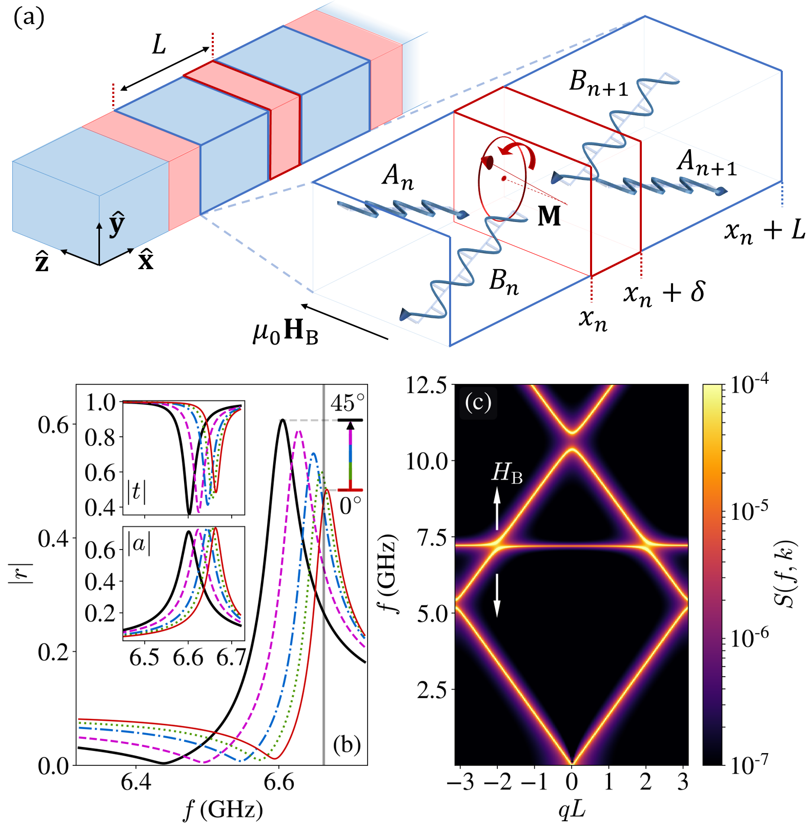
The metamaterial design studied here and shown in Fig.1(a) is based on the insights obtained from our analysis of the acoustic scattering by isolated thin magnetic slabs.13 The magnetoelastic coupling within a slab manifests itself as a peak in the frequency dependence of its reflectivity. This peak corresponds to the Kittel frequency of the slab and is therefore controlled by the bias magnetic field. The strength of the coupling between the localised magnetic and propagating acoustic modes is enhanced for an oblique incidence [see Fig.1(b)]. As a result, for realistic values of the magnetoelastic coupling, , a noticeable effect is achieved for small values of the Gilbert damping, e.g. . For practical uses though, this response needs to be enhanced further. One potential route is to slow down the acoustic modes, increasing their interaction time with the magnetic slabs. This could occur in the vicinity of phononic band gaps. The structure factor of a phononic crystal with embedded magnetic slabs [see Fig.1(c)] exhibits a magnetically tunable anticrossing with the usual phononic dispersion. We expect an enhancement of the response of such a structure when the magnetoacoustic resonance leading to this anticrossing is tuned to the proximity of the band gap.
The 1D array analyzed here is a simple implementation of this design idea. Its elementary building blocks are thin ferromagnetic slabs of thickness , infinite in the plane, and separated by nonmagnetic spacer layers of thickness , as shown in Fig.1(a). The slabs are magnetized by a bias magnetic field and have saturation magnetization . The array either contains a finite number, , of magnetic slabs, or is semi-infinite. Let the resonator be situated at , where is the period of the array. As in Ref. (13), we assume that the elastic properties of the two materials may differ. Transverse acoustic waves are obliquely incident on the array from the left. The shear stress produced by the waves perturbs the slabs’ magnetization, as described by the standard magnetoelasticity theory.16; 10; 17
The magneto-acoustic response of finite arrays are characterized by the reflection, , transmission, , and absorption, , coefficients. Using the transfer matrix method,18 these coefficients can be expressed via the reflection, and transmission, , coefficients in the forward direction and the reflection, , and transmission, , coefficients in the backward direction. The coefficients , , , and exhibit a strong frequency dependence, which is not specified explicitly here but can be found in Ref.(13). In particular, this dependence features a Fano resonance near the Kittel frequency, as shown in Fig.1(b).
The oblique incidence geometry adopted here, exhibits a transverse acoustic displacement inside the layer, , of the nonmagnetic material is given by
| (1) |
where . In what follows, we retain only the -dependence of the wave function. Hence, and represent the amplitudes of acoustic modes traveling to the right and to the left in the nonmagnetic layer, respectively. Then, for a wave of unit amplitude incident from the left onto a finite array, we have , , , . To form the transfer matrix, , for a single period of the array, amplitudes at and can be related via forward (, ) and backward (, ) transmission and reflection coefficients. Indeed, matching incoming and outgoing waves at the slab, we write
| (2) |
where is the acoustic phase delay between two neighboring slabs. The transfer matrix is then constructed by inverting Eq. (2) as
| (3) |
The action of can be represented by its eigenvalues and eigenvectors. The eigenvalues that solve the characteristic equation are given by , where and . From Eq. (3), we find that which has absolute value of one. As usual, we find that the two eigenvalues of either both lie on the unit circle , or one is inside and the other is outside. In our system, the energy is dissipated due to the Gilbert damping. Hence, we can define so that , representing the wave propagating to the right. For a finite array of resonators, the full transfer matrix retains the eigenvector basis with eigenvalues . The initial and final state amplitudes are then projected onto a reciprocal of this basis, multiplied by the eigenvalues, and resolved to obtain for the finite array’s reflection coefficient
| (4) |
where is the reflection from a semi-infinite array,
| (5) |
and is defined as,
| (6) |
The transmission coefficient of the finite array is then given by
| (7) |
The absorbance can be found as . We remind the reader that the parameters and depend on the frequency and the phase delay .
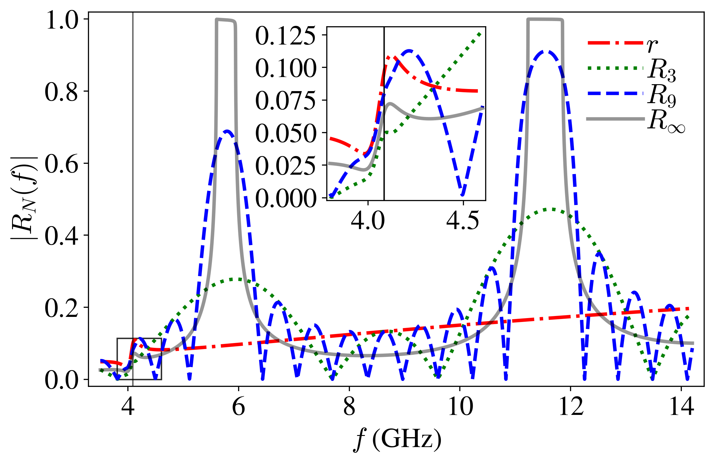
To illustrate how depends on the number of elements in a finite array, we have performed detailed calculations for an array of nickel slabs (mass density , magnetoelastic coupling coefficient , shear modulus , gyromagnetic ratio , saturation magnetization , 19; 20) embedded into a silicon nitride matrix (, , 21; 20 ). Fig.2 presents results of the calculations for a generic case, without fine-tuning of the magnetoelastic resonance. For , the absolute value of the reflection coefficient has the unity value in frequency regions corresponding to the acoustic stopbands (phononic band gaps). These are caused by the mismatch of the acoustic impedance at slabs’ surfaces and occur even in the absence of magnetoelastic coupling ().22; 23; 24 Each passband contains peaks, which are due to the phase delay of the acoustic waves increasing by across each Brillouin zone.18 The magnetoelastic coupling () manifests itself via an asymmetric peak due to the Fano resonance, positioned at the Kittel frequency at .7
The rapid oscillation in passbands in Fig.2 is due to the multiple reflections within an array of finite size. For sufficiently large arrays (i.e. when the decay length is smaller than the array size), these oscillations are suppressed. Indeed, the oscillations are suppressed for (calculated using Eq. (5) and shown by the solid line in Fig.2), as expected for . So, our subsequent analysis is focused on the semi-infinite array.
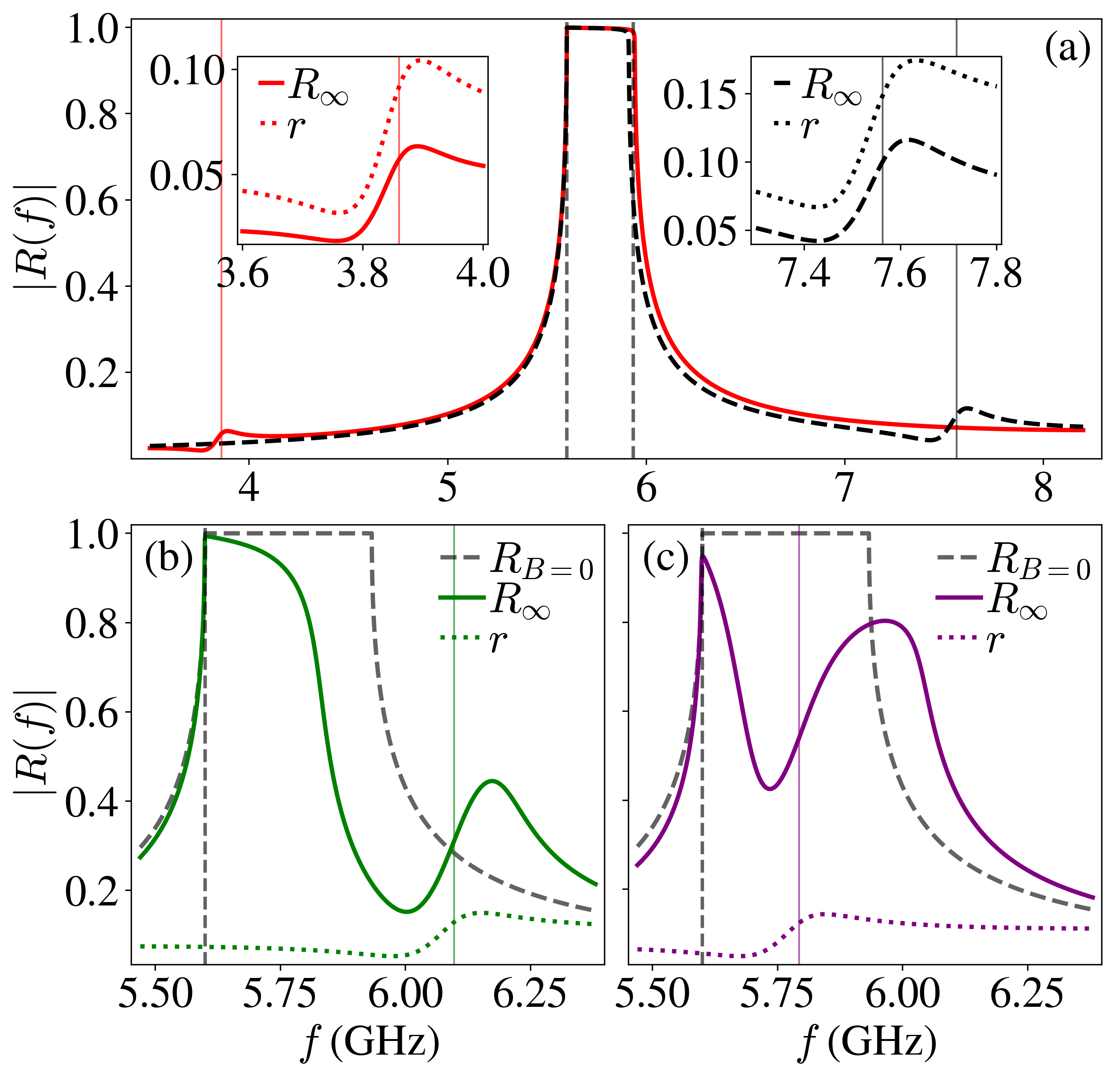
Fig.3 displays the reflectivity , of a semi-infinite array over frequency for several positions of the Kittel resonace. We identify three regimes based on the positioning of relative to phononic band gaps. Regime I (‘detuned’) occurs as is tuned inside a passband, away from band edges. Shown by Fig.3.(a), with insets providing comparison of with . In both cases (tuned above or below), the peak in is lower than that in . This suppression is caused by the destructive interface of backward reflected waves, which is pronounced away from band edges.
Regime II (‘adjoining’) occurs as the Kittel frequency , approaches the band gap from a passband. Here the resonant scattering becomes highly sensitive to the detuning of from the band edge. In close proximity to the band gap, where the Bragg condition holds, the scattering is enhanced. (In other words, destructive interference crosses over to constructive.) Inside the band gap the reflectivity is reduced, which may be interpreted as induced transparency. This reduction in reflectivity is caused by the magnetoacoustic hybridization providing slowly propagating hybrid modes inside the band gap. Indeed, Kittel resonances in the magnetic elements may hybridise via ‘virtual phonons’ in the stop band. This would introduce a non-zero density of states inside the band gap which can also be seen as coherent reflections in a finite array.
Regime III (‘inner’) occurs as the Kittel frequency , is tuned inside the band gap. The main feature of this regime is the reduced reflectivity, as seen in Fig.3.(c). This reduction is not symmetric as the bias field sweeps the Kittel resonance over the band gap. We see that the behaviour at the upper and the lower edge is distinctly different: the reflectivity is reduced as approaches the upper band gap frequency. This phenomenon can be attributed to the Borrmann effect.25; 26 In a pure phononic crystal () the modes at the band edges are two standing waves, phase shifted by .27 For one of the modes the maxima of the stress occur in magnetic slabs, while for the other this pattern is reversed: the slabs become the nodes. When the modes are coupled to the magnetisation dynamics in the slabs, the dissipated energy depends primarily on the local stress. Hence absorption is suppressed for the latter, nodal mode.15 This mode occurs at the lower band edge if the acoustic impedance of the magnetic (M) material is larger than that of the non-magnetic matrix (NM): . This gives rise to the asymmetry seen in Fig.3. (The asymmetry is reversed when .)
We note that magneto-elastic effects shown in Fig.3 remain significant even for a realistic damping value . This is a considerable improvement compared with a single resonator where a similar damping value would completely suppress the Fano features.13 A shift in lower band edge [see Fig.3.(a)] is induced by proximity to the Kittel frequency . This band shift and the induced transmission are resolved separately as sweeps the band gap when the band gap width significantly exceeds the Fano resonance linewidth.
To characterise the tunability of the magnetoelastic resonance we introduce the modulation coefficient showing the variation of by . As is tuned around band gaps the reflectivity becomes sensitive to changes in the external bias field , as illustrated by in Fig.4.(a). Here, the first three band gaps show this phenomena occuring at higher band frequencies. However, operating a device in this high-frequency regime may be impractical as e.g. it would require a large bias field (T).
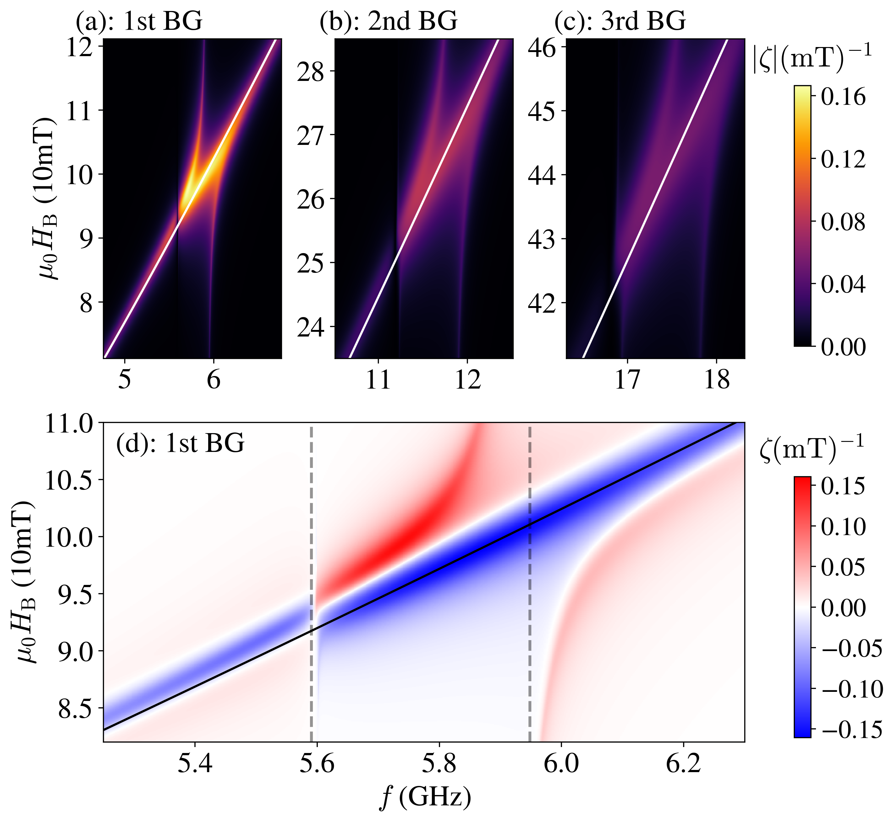
Fig.4.(d) provides an insight into the behaviour in the first band gap. We see that is enhanced in a close proximity to the band gap edges (dashed gray) and the Kittel frequency (solid black), rapidly changing from positive (red) to negative (blue). Frequencies around the Kittel resonance are either increased or decreased in frequency by coupling to spin wave modes [see Fig.1.(c)]. Band edges are influenced by this shift in frequency, relative to their own position with respect to the magneto-elastic anti-crossing. For larger band widths and closer proximity to the Kittel frequency this shift is enhanced. At the lower band edge, the Borrmann effect counteracts the shift [see Fig.3.(a)]. The Borrmann effect also results in the asymmetry below the lower band edge (GHz), as the Fano resonance reconstructs its lineshape around when exiting the bad gap.
In summary we have shown that the metamaterial approach is indeed helpful for magnetoacoustics. Hybrid metamaterials, formed by 1D arrays of resonators, magnify the effects of magnetoelastic coupling, thus mitigating the Gilbert damping to tolerable levels. The structures considered here are tunable by an applied bias field and exhibit a rich and complex behaviour, such as induced transmission and Borrmann asymmetry. To prototype realistic structures, we aim to investigate higher dimensions and implement surface acoustic waves. We envision the characteristics shown here will prove useful when engineering sensors, actuators, radio frequency modulators and reconfigurable magnonic devices.
The research leading to these results has received funding from the Engineering and Physical Sciences Research Council of the United Kingdom (Grant No. EP/L015331/1) and from the European Union’s Horizon 2020 research and innovation program under Marie Skłodowska-Curie Grant Agreement No. 644348 (MagIC).
References
- Perrucci, Fitzek, and Widmer (2011) G. P. Perrucci, F. H. P. Fitzek, and J. Widmer, “Survey on energy consumption entities on the smartphone platform,” IEEE VTC P. 73 , 1 (2011).
- Liang et al. (2019) Y. Liang, C. Zhao, H. Yuan, Y. Chen, W. Zhang, J. Hung, D. Yu, Y. Liu, M. Titirici, Y. Chueh, H. Yu, and Q. Zhang, “A review of rechargeable batteries for portable electronic devices,” InfoMat 1, 6 (2019).
- Gurevich and Melkov (1996) A. G. Gurevich and G. A. Melkov, Magnetization Oscillations and Waves (Chemical Rubber Corp., New York, 1996).
- Kruglyak, Demokritov, and Grundler (2010) V. V. Kruglyak, S. O. Demokritov, and D. Grundler, “Magnonics,” J. Phys. D: Appl. Phys. 43, 264001 (2010).
- Krivoruchko (2015) V. N. Krivoruchko, “Spin waves damping in nanometre-scale magnetic materials (review article),” Low Temp. Phys. 41, 670 (2015).
- Azzawi, Hindmarch, and Atkinson (2017) S. Azzawi, A. T. Hindmarch, and D. Atkinson, “Magnetic damping phenomena in ferromagnetic thin-films and multilayers,” J. Phys. D: Appl. Phys. 50, 473001 (2017).
- Kittel (1958) C. Kittel, “Interaction of spin waves and ultrasonic waves in ferromagnetic crystals,” Phys. Rev. 110, 836 (1958).
- Bömmel and Dransfeld (1959) H. Bömmel and K. Dransfeld, “Excitation of hypersonic waves by ferromagnetic resonance,” Phys. Rev. Lett. 3, 83 (1959).
- Dreher et al. (2012) L. Dreher, M. Weiler, M. Pernpeintner, H. Huebl, R. Gross, M. Brandt, and S. Goennenwein, “Surface acoustic wave driven ferromagnetic resonance in nickel thin films: Theory and experiment,” Phys. Rev. B 86, 134415 (2012).
- Callen and Callen (1965) E. Callen and H. B. Callen, “Magnetostriction, forced magnetostriction, and anomalous thermal expansion in ferromagnets,” Phys. Rev. 139, A455 (1965).
- Kamra et al. (2015) A. Kamra, H. Keshtgar, P. Yan, and G. E. W. Bauer, “Coherent elastic excitation of spin waves,” Phys. Rev. B 91, 104409 (2015).
- Graczyk, Kłos, and Krawczyk (2017) P. Graczyk, J. Kłos, and M. Krawczyk, “Broadband magnetoelastic coupling in magnonic-phononic crystals for high-frequency nanoscale spin-wave generation,” Phys. Rev. B 95, 104425 (2017).
- Latcham et al. (2019) O. S. Latcham, Y. I. Gusieva, A. V. Shytov, O. Y. Gorobets, and V. V. Kruglyak, “Controlling acoustic waves with magneto-elastic fano resonances,” Appl. Phys. Lett. 115, 082403 (2019).
- Limonov et al. (2017) M. F. Limonov, M. V. Rybin, A. N. Poddubny, and Y. S. Kivshar, “Fano resonances in photonics,” Nat. Photonics 11, 543 (2017).
- Novikov and Murzina (2017) V. B. Novikov and T. V. Murzina, “Borrmann effect in photonic crystals,” Opt. Lett. 43, 1389 (2017).
- Comstock and Auld (1963) R. L. Comstock and B. A. Auld, “Parametric coupling of the magnetization and strain in a ferrimagnet. i. parametric excitation of magnetostatic and elastic modes,” J. Appl. Phys. 34, 1461 (1963).
- Akhiezer, Bar’yakhtar, and Peletminskii (1968) A. I. Akhiezer, V. G. Bar’yakhtar, and S. V. Peletminskii, Spin waves (North-Holland, Amsterdam, 1968).
- Markos and Sokoulis (2008) P. Markos and C. M. Sokoulis, Wave Propagation (Princeton University Press, 2008).
- Berk et al. (2019) C. Berk, M. Jaris, W. Yang, S. Dhuey, S. Cabrini, and H. Schmidt, “Strongly coupled magnon-phonon dynamics in a single nanomagnet,” Nat. Commun. 10, 2652 (2019).
- Inc. (2019) A. C. Inc., “Matweb: Material property data,” http://www.matweb.com/index.aspx (2019), Accessed: 2019-11-14.
- Huszank, Csedreki, and Z. Kertész (2016) R. Huszank, L. Csedreki, and Z. T. Z. Kertész, “Determination of the density of silicon–nitride thin films by ion-beam analytical techniques (rbs, pixe, stim),” J. Radioanal. Nucl. Chem. 307, 341 (2016).
- Martin, Abrahams, and Parnell (2015) P. Martin, I. Abrahams, and W. Parnell, “One-dimensional reflection by a semi-infinite periodic row of scatterers,” Wave Motion 58, 1 (2015).
- Born and Wolf (1964) M. Born and E. Wolf, Principles of Optics (Pergamon, Oxford, New York, 1964).
- Brekhovskikh and Godin (1997) L. M. Brekhovskikh and O. A. Godin, Acoustics of Layered Media (Springer, Berlin/Heidelberg, 1997).
- Campbell (1951) H. N. Campbell, “X-ray absorption in a crystal set at the Bragg angle,” J. Appl. Phys. 22, 1139 (1951).
- Batterman and Cole (1964) B. W. Batterman and H. Cole, “Dynamical diffraction of x-rays by perfect crystals,” Rev. Mod. Phys. 36, 681 (1964).
- Croënne et al. (2011) C. Croënne, E. J. S. Lee, H. Hu, and J. H. Page, “Band gaps in phononic crystals: Generation mechanisms and interaction effects,” AIP Adv. 1, 041401 (2011).