Studies of the beam-ion instability and its mitigation with feedback system
Abstract
The beam-ion interaction is a potential limitation of beam performance in electron accelerators, especially where the beam emittance is of a great concern in future ultra-low emittance light source. “Conventionally”, the beam instability due to beam-ion interaction is attributed to two types of effects: ion trapping effect and fast ion effect, which emphasize the beam-ion dynamics in different time scales. Whereas, in accelerators, the beam suffers from a mixture of ion trapping effect and fast ion effect, leading to a more complicated process and requiring a self-consistent treatment. To evaluate the beam characteristics, as emittance growth under the influence from beam-ion effect, a new numerical simulation code based on the “quasi-strong-strong” model has been developed, including modules of ionization, beam-ion interaction, synchrotron radiation damping, quantum excitation, bunch-by-bunch feedback, etc. In the study, we do not regularly distinguish the ion trapping effect and the fast ion effect, but treat beam-ion interaction more generally and consistently. The lattice of High Energy Photon Source, a diffraction limit ring under construction in Beijing, is used as an example to show the beam-ion effect. It is found that in this low emittance ring, the beam-ion instability is not a dominant mechanism in operation mode with a high beam current, but seriously occurs in a lower beam current region. When the beam-ion instability were significantly driven and can not be damped by the synchrotron radiation damping, the simulations show the bunch-by-bunch feedback system based on the Finite Impulse Response filter technique can be adopted to mitigate it effectively.
pacs:
41.75.-i, 29.27.Bd, 29.20.EjI Introduction
The beam-ion interaction, a two-stream effect coupled by the nonlinear Coulomb force, may pose a risk to the operation of future electron accelerators with beams of high intensity and ultra-low emittances. The effect of beam-ion interaction has been observed in many existing accelerator machines such as ALS Zimmermann et al. (1997); Byrd and Chao (1997), PLS Kwon et al. (1998), SSRF Jiang et al. (2010) CESR-TA Chatterjee et al. (2014), SOLEIL Nagaoka et al. (2007), etc. The accumulated ions, derived from ionization between electron particle and residual gas molecules, interact with the electron beam particles resonantly, causing coherent and incoherent electron beam deformation, such as beam centroid oscillation, beam rms emittance growth, rms beam sizes increasement, energy spread blow up, and even a possible beam loss.
In the previous studies, the beam-ion effect Raubenheimer and Zimmermann (1995); Stupakov et al. (1995); Ohmi (1997) is divided into two circumstances known as ion trapping effect and fast ion effect. In the study of ion trapping effect, one of the key conclusions is the ion trapping condition Stupakov et al. (1995),
| (1) |
where is the bunch population, is the classical proton radius, is the bunch spacing, is the speed of light, and are the rms beam size. Ions with mass number lower than will be over-focused by the bunched beam particles and hardly disturb the beam performance. Ions with a mass larger than the critical value will be trapped transversely in the space charge potential well of the electron beam and impact the electron beam particles turn by turn leading to a beam performance deterioration, or even beam losses. It is noteworthy that the ion trapping condition is based on the linear space charge and even beam filling pattern assumptions; moreover, the critical mass varies along the accelerator since the betatron function varies, which indicates the ions trapping sections are localized actually. To simplify the theoretical analysis and approaches adopted in numerical simulations for ion trapping study, it is usually assumed that the accumulated ions are saturated to an equilibrium state over thousands turns – a steady state sense. In this equilibrium state frame, a beam-ion eigen-system can be established and used to predict the coupling resonance conditions, which is a typical methodology in two stream instability studies Ohmi et al. (2001). Results obtained from ion trapping are usually used as guidances for vacuum selection and beam intensity up-limits prediction.
Correspondingly, the fast ion effect focuses on the transient effect in one turn. The ions generated in the first turn are cleaned and will not disturb the beam performance in the second turn. In the time scale of one turn, the ions generated by the leading bunches oscillate transversely and resonantly disturb the motions of the subsequent bunches – coupled bunch instability in a transient sense. Then the ions are assumed to be cleaned over one turn. Generally, the fast ion effect disturbs the beam performance both in linacs and storage rings in a spontaneous manner.
In general, the transient net ions accumulated is a compromise of ions generation rate due to ionization and ion loss rate due to momentum kicks from bunched beam passed by. Clearly, the ion trapping effect and fast ion effect are both derived from the beam-ion Coulomb interaction, but emphasize the dynamics process in different time scales. In reality, these approximations adopted in ion trapping effect and fast ion effect are always violated by constraints such as uneven beam filling pattern, residual ions accumulated turn by turn, etc, which lead to the theoretical task impossible to complete. In reality, ion trapping and fast ion effect could take place simultaneously. In this paper, we do not distinguish the ion-trapping and fast ion effects and treat the beam-ion motions consistently. To evaluate the beam performance, such as beam emittance evolution, a new numerical code based on the “quasi-strong-strong” approach is developed Chao Li , in which electron particles and ions are both represented by multi-macroparticles. Moreover, modules of ionization, beam-ion interaction, synchrotron radiation damping, quantum excitation and bunch-by-bunch feedback are also established. As an example, High Energy Photon Source (HEPS) Jiao et al. (2018) lattice is adopted to show the beam-ion effect in detail. It will be shown that in this ultra-low emittance ring, the beam-ion interaction significantly influences the beam performance only when ions can be extensively accumulated in certain current region. If the beam current in the operation is high enough, the ions will be over-focused, get lost in gaps between neighbouring bunches, and hardly influence the beam.
To suppress the beam-ion instability, the bunch-by-bunch feedback system is applied in this paper. Generally, the methodologies to mitigate the beam-ion effect are: (1) adjust the beam filling pattern by including empty buckets long enough in the bunch train; (2) get rid of ions with certain accelerator elements, such as cleaning electrodes where ions can be collected; (3) cure the beam-ion instability by introducing a feedback system before it grows Wang et al. (2011). The first approach can extensively reduce the number of accumulated ions. With sufficient large empty gaps, the trapped ions would drift to large amplitudes, where they may get lost on the pipe or form a diffuse ion halo that hardly influences the beam. However, this approach is a partial solution since the disturbed bunch can not erase the memory itself. The beam deformation by the beam-ion interaction will accumulate and the influence will be shown finally, unless the synchrotron radiation damping is pretty strong. The second and the third approaches both require extra hardware, which brings in new sources of lattice impedance. However, the bunch-by-bunch feedback system is a versatile system Lonza and Schmickler (2016). It also can be used to suppress the beam instabilities lie in impedance.
This paper is organized as follows, in section II, the physical process and models of beam-ion interaction will be discussed briefly. The logic flow and basic approaches used in the code will be given. In section III, both the “weak-strong” and “quasi-strong-strong” simulations of the beam-ion effect in HEPS will be discussed in detail. The bunch-by-bunch feedback will be discussed in Section V. By introducing an appropriate feedback system, the beam-ion instability can be effectively suppressed. The discussion and conclusion are given in Section IV.
II Physical model and the logical flow in the code developed.
Ignoring the ions generated from the synchrotron radiation, which are usually far outside the beam and equally distributed between the beam and chamber wall, denoting and as the vacuum pressure and temperature, the molecules density in the accelerator can be obtained from the general gas equation,
| (2) |
where and are the ideal gas constant and the Avogadro number. Denote as the ionization cross-section, as the number of electron particles passing by, the number of ionization ions per unit length is
| (3) |
For simplicity, the interaction between ions and beam is assumed taking place at lumped interaction locations, and the ions are assumed not to move longitudinally. It is noteworthy that, when beam passes through interaction points bunch by bunch, new ions will be repeatedly generated with a minimum time interval , which is the period of fundamental radio frequency indicating the spacing between adjacent bunches. The ions generated are randomly distributed in the same range as the size of the electron bunch passing by. Meanwhile, the accumulated ions are kicked by the passing bunched electron particles and then drift freely until next electron bunch comes. Some of the ions might get lost on the pipe. Due to the ions generation and loss mechanisms, a dynamical quasi-equilibrium ion distribution can be foreseen finally. The motion equations of the th accumulated ion and the th electron particle in the th bunch can be expressed as
| (4) |
where is the Coulomb force between the ions and electron particles, and represent the lattice focusing strength on ion and beam particle.
Eq. II describes the beam-ion dynamics in a general sense but almost impossible to be applied directly in theoretical analysis. To launch that, several approaches can be adopted to simplify the analytical study, as
-
1.
the smooth approximation to get a time-independent focusing lattice;
-
2.
the equilibrium state assumption of the accumulated ions – constant ion charge;
-
3.
the linear space charge approximation.
More detailed information can be found in Ref. Raubenheimer and Zimmermann (1995); Stupakov et al. (1995).
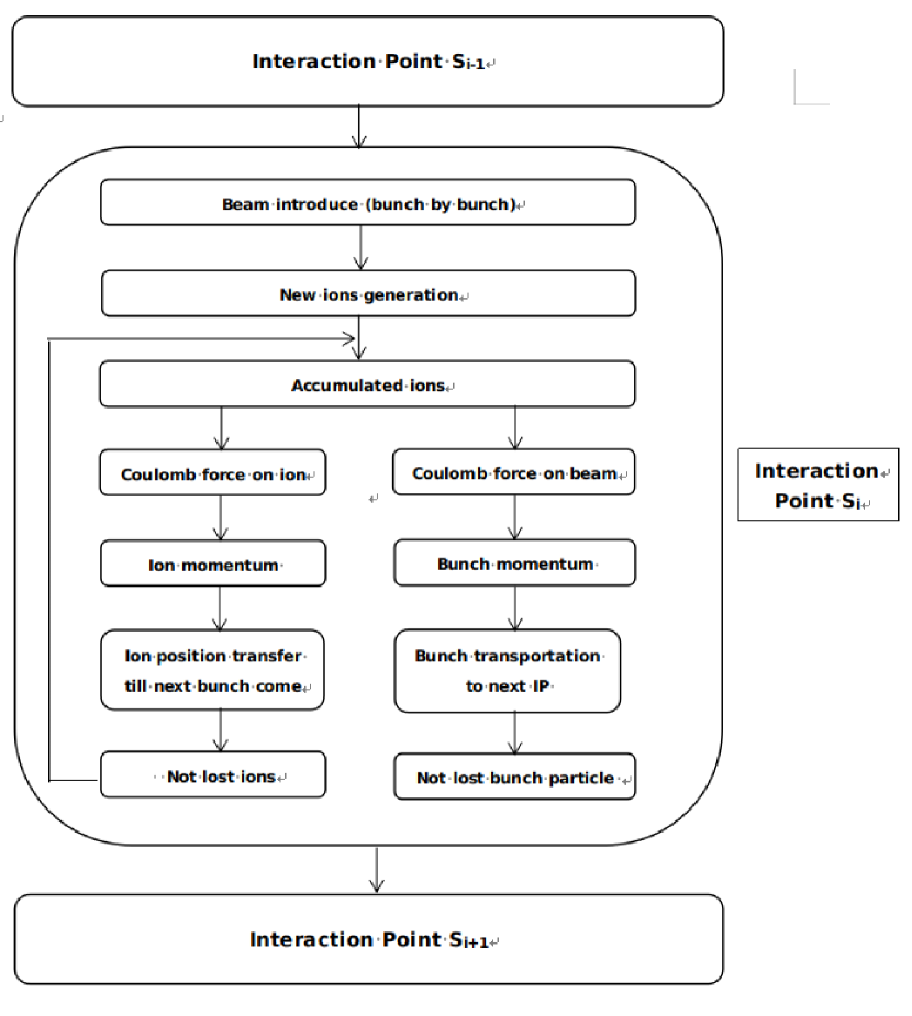
Here, we briefly introduce the numerical approaches used in the code developed Chao Li . Fig. 1 shows the logic flow of the simulation process at the interaction points. The continuous interaction between ions and beam particles is limited to lumped interaction locations. Arbitrary number of interaction points with various local lattice functions, Twiss parameters, temperatures and gas pressures can be specified in the code. In the simulation model, both the ions and electron bunches are represented by macro-particles. The electron bunch with particles is assumed to follow a rigid Gaussian distribution in real space, which is rather reasonable. At the interaction point , the 2D Bassetti-Erskine formula Bassetti, M and Erskine, George A (1980) is used to get electron field generated by the bunched electron particles,
| (5) | |||||
where is the line density of the electron beam, is the complex error function, and are the beam rms size in horizontal and vertical direction, and are the distance from ions to the bunch centroid, is the complex unit. Substituting Eq. 5 into Eq. II, the explicit momentum change of ions at the interaction point is
| (6) |
where is the classical electron radius, is the electron mass, is the speed of light, is the relativistic factor of electron beam. Since the ions are much heavier than the electron, the lattice focusing can be ignored. Integrating Eq. 6 along the length of adjacent electron bunches, the accumulated ion momentum change induced by the electron bunch passed by can be obtained.
As to the space charge potential well generated by the ions, since the ions distribution is usually not a Gaussian type and the ion particles almost occupy the whole pipe, in principle the Bassetti-Erskine formula is not suitable anymore. A self-consistent particle-in-cell (PIC) Li et al. (2014) solver or ion density profile fitting 17 (17) is needed to ensure a better resolution. In our code, a compromise approach is applied. The ions distribution is truncated at 10 rms bunch size. The rms and centroid information of the truncated ion distribution are substituted in the Bassetti-Erskine formula to get the Coulomb potential. Although this approach is not as self-consistent as PIC, it still can show the main features of the bunched beam and explore this complex coupled dynamics in a reasonable computing time. The vacuum chamber aperture is used as the ions and electron particle loss criteria; Only the survived ions and electron particles are kept for further calculation. When one electron bunch particles passes by, the transverse momentum and position of the accumulated ions are updated according to the time interval until the next bunch comes. As to the bunched electron particles, after the momentum kicks induced by the accumulated ions, they are transferred to the next interaction point by applying the linear transport matrix.
With a monotonically increasing of the bunched beam size due to beam-ion interaction, a saturated accumulated ions with a sharp center density profile can be foreseen Wang et al. (2011). In our code, both the electron bunched beam and ions are represented by multi-particles – “quasi-strong-strong” model. Compared with the linear space charge assumption or “weak-strong” model, where the growth rate of the beam-ion instability is overestimated, the “quasi-strong-strong” includes ion and beam transverse oscillation frequency spreads spontaneously that eases the beam-ion instability through Landau damping. However, it is still noteworthy that there are gaps between the Gaussian profile assumption and the real beam (or ion) distributions. To get a more self-consistent process and better accuracy, a general Poisson solver is required in further study .
Summing up, the characteristics of code are:
-
1.
settings of arbitrary ion species, arbitrary number of beam-ion interaction points where the local gas pressure and temperature are specified;
-
2.
including synchrotron radiation damping and quantum excitation;
-
3.
including bunch-by-bunch feedback modules;
-
4.
“quasi-strong-strong” model;
-
5.
Gaussian distribution assumption in the beam-ion space charge calculation;
III Simulation study of beam-ion interaction in HEPS without feedback.
| Parameters | Values |
|---|---|
| Energy | 6 GeV |
| Circumference | 1360.4 m |
| Nominal emittance | 34.2 pm |
| Working points | 114.14/106.23 |
| Number of super-periods | 24 |
| Average betatron function | 4.5/8.1 m |
| Number of RF bucket | 756 |
| Beam current | 200 mA |
| SR damping time (x/y) | 2386/4536 turns |
| rms beam size (x/y) | 12.4/5.26 m |
| Ion species | CO |
| Gas pressure | 1 nTorr |
| Gas Temperature | 300 K |
HEPS is a 1.3 km ultra-low emittance electron storage photon source being built in Beijing, China. The main parameters of HEPS lattice are listed in Tab. I. Carbon monoxide (CO) is assumed as the leaked gas with pressure 1 nTorr and temperature 300 K. At the beam operation stage with 200 mA beam current, the critical mass number of ion trapping condition is 111The average betatron function is used to estimate the ion trapping condition.. In the following study, the total electron beam current 10 mA () is adopted to evaluate the beam-ion effect, since it gives the most serious beam-ion effect which will be explained below. To save computing time, one beam-ion interaction point is set per turn. The beam filling pattern is one continuous bunch train following 76 empty bunch gaps. The synchrotron radiation damping and quantum excitation Zhang et al. (2005) are both taken into account.
In this section, results from “weak-strong” and “quasi-strong-strong” model both will be discussed in detail. In the “quasi-strong-strong” model, the beam and ion density variations are intrinsic included, leading to ion and beam transverse oscillation frequency spreads. These frequency spreads are supposed to ease the beam-ion instability through Landau damping. Another necessity of the “quasi-strong-strong” simulation study is the beam emittance growth evaluation, which is one of the key challenges in ultra-low emittance rings.
III.1 “Weak-Strong” Simulation
In the “weak-strong” model, the electron bunch is represented by a rigid Gaussian distribution. In the code, setting one macro electron particle per bunch, the simulation automatically degenerates to the “weak-strong” case. Smaller vertical beam emittance leads to more serious beam deformation in vertical space. Following the approaches used in previous researches Ohmi (1997); Xia and Elsen (2008), the maximum bunch dipole moment is recorded turn by turn. The vertical amplitude of the bunch centroid oscillation is half of the Courant-Synder invariant, which is give by
| (7) |
where are the local Twiss parameters at the interaction point.


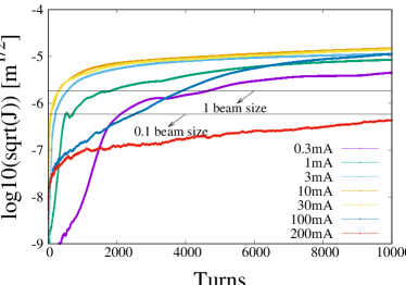
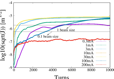
Fig. 2 shows the maximum bunch action as function of tracking turns in “weak-strong” simulation. The sub-figures at left and right correspond to simulation without and with synchrotron radiation damping. In each sub-figure, there are 7 curves related to beam currents: 0.3 mA, 1 mA, 3 mA, 10 mA, 30 mA, 100 mA and 200 mA. For each beam current, the maximum bunch action performs a sustained increasing due to the beam-ion interaction and finally arrive to a “constant” value after 10 thousands turns evolution. The final beam action increases with beam current firstly and reaches a maximum value (10 mA) and then decreases. This is because of the net accumulated ion number is a nonlinear function verse beam current. Fig. 2 also depicts that the beam is still significantly impacted by the ions till 100 mA. Up to 200 mA, the bunched beam is hardly impacted and the centroid oscillation is smaller than 0.1 rms beam size, which is because the trapping condition can not hold anymore and the ions are over-focused and got lost in the empty gaps between the neighbouring bunches. Comparing the results with and without synchrotron radiation damping, the final bunch actions become smaller and get into a equilibrium state sooner when the synchrotron radiation damping is turned on.
It is noteworthy that the spontaneous synchrotron radiation damping in HEPS can not stabilize the beam-ion instability except the ions are over-focused in 200 mA case. In the following discussion, if not stated, 10 mA beam current is chosen as a default case to show the characteristics of the beam-ion interaction. Fig. 3 illustrates the bunch centroid oscillation and its coupled mode spectrum when the synchrotron radiation damping is turned on. The oscillations of different bunches show a clear coupled “head-tail” style motion as expected. With the turn number increasing, more and more bunches at the tail part start to oscillate which is one of the typical characteristics of the beam-ion instability. The maximum unstable mode index is around 50 (70) in () direction.


In simulations, the ion particle is marked as a lost one either it beyonds 10 times effective rms beam size or beyonds the pipe aperture. Fig. 4 shows the total accumulated ion charge as function of tracking turns in the “weak-strong” model. Similar to Fig. 2, the figures at left and right correspond to results without and with synchrotron radiation damping. Dynamically, the accumulated ion charge is a compromise between ions generation rate and ions loss rate. The ion loss rate lies in the ion’s accumulated transverse momentum obtained from the electron bunch. With a higher beam current, more ions can be generated by ionization; however, stronger beam-ion interaction also enlarges the ions loss rate conversely. Without the synchrotron radiation damping, the accumulated ion number does not reach an equilibrium state after 10 thousand turns. More ions are accumulated since a larger beam action leading to a larger average distance between new generated ions and the centroids of coming bunches.
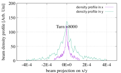
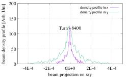
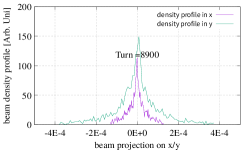
Fig. 5 shows the ion density profile variation at the 8000th, 8400th and 8900th turns, when the “quasi-equilibrium” is arrived in the “weak-strong” simulation with synchrotron radiation damping. The centre of the density profile shows an oscillation due to the beam-ion interaction and the oscillation amplitude is consistent with the maximum bunch oscillation in Fig. 2 and Fig. 3. The frequency of the ion density oscillation can be estimated by even filling pattern approximation Ohmi (1997). It is noticeable that the ion density profile deviates from the Gaussian type with a higher density peak in the center as discussed in Ref. Wang et al. (2011). In the future study, a self-consistent space charge solver is required for a better resolution.
III.2 “Quasi-strong-strong” simulation


In the “weak-strong” model, the electron bunch is represented by one macro-particle and it can not give information on beam effective emittance growth. In this subsection, the “quasi-strong-strong” model is adopted to evaluate the effective beam emittance growth 222Rms emittance reference to the idea orbits.. Both the ions and electron bunches are represented by macro-particles. Still, the Bassetti-Erskine formula Eq. 5 is applied to get the space charge force between ion and beam as explained in section II.
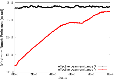
Fig. 6 shows the bunch oscillations in horizontal and vertical directions, accumulated ions and beam effective emittance growth in “quasi-strong-strong” simulation when the synchrotron radiation damping is turned on. The maximum bunch centroid oscillation is roughly 0.1 and 10 times rms beam size in and direction respectively; The accumulated ions charge gets smaller when the “quasi-equilibrium” is reached. Fig. 6d gives the maximum effective bunch emittance (reference to the ideal orbit) revolution as function of tracking turns. The effective bunch emittance continuously increases in vertical direction and beyonds the error budget. The horizontal beam emittance does not change too much even after 10 thousand turns evolution. In the following section IV, a bunch-by-bunch feedback system based on Finite Impulse filters (FIR) filter techniques will be introduced to mitigate the beam-ion instability and control the beam emittance growth.
IV Bunch-by-bunch Feedback and its influence on beam performance
The bunch-by-bunch feedback based on the FIR filter is an effective way to cure the coupled bunched instability. It detects transverse or longitudinal centroid positions of beam bunches, processes the positions data to create kicker signals, and adds transverse or longitudinal kicks to the beam particles to damp its oscillations. Noticeably, in this process, only centroid oscillations of passed bunches are used. The momentum changes of particles in the bunched to be kicked are the same. Thus, the bunch-by-bunch feedback damping effect is in an average scene. In general, the spectrum of coupled bunch mode spectrum is
| (8) |
where is the harmonic number, is integer, is the mode index and is the revolution frequency Chao (1993). The well designed FIR filter, with Direct Current (DC) rejection, has zero amplitude response at arbitrary harmonics of the revolution frequency . Clearly, by adopting the FIR filter, only the fraction of betatron oscillation frequency over revolution frequency matters. That is the reason why the unstable coupled bunch mode can be damped.
Eq. 9 is the general form of a FIR filter
| (9) |
where represents the filter coefficient, and are the input and output of the filter, corresponding to beam position data at the th turn and kick strength on the beam at the th turn. The number of the input data is defined as taps. Following the approaches shown in Ref. Nakamura , the time domain least square fitting (TDLSF) method is used to get the filters coefficients .
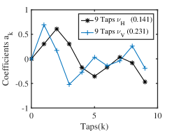
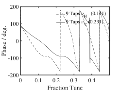
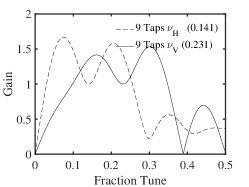
With the condition of one turn delay , two 9-taps FIR filters are designed. For clarity, the pickup and kicker are assumed to be located at the same place with zero dispersion, which means the phase responses at target tunes are -90 degree. Fig. 7 shows the filter coefficients, the phase and amplitude responses as function of fraction tune in horizontal and vertical directions. The first derivation of the phase response curves at target tunes are designed to be zero to enlarge the phase error tolerance. The stable working region corresponds to the feedback phase response curve between (-180,0) degrees. The gain at the target tune is local minimum and normalized to 1. The DC components which are caused by the closed orbit distortions, unequal bunch signal shapes from pickup electrodes and reflection at cable connections are rejected.
The shortest damping time of the feedback can be approximated Lonza and Schmickler (2016); Nakamura by
| (10) |
where is revolution frequency, is the harmonic number, and are the betatron function at pickup and kicker, is the beam energy, is the electron unit charge, is the maximum bunch oscillation that the feedback can suppress, is the kicker shut impedance and is the maximum available kicker power. In HEPS, the kicker shut impedance is K at the location with m, assuming the power limit on kicker is KW and mm, the shortest damping time of the feedback can supply is roughly 60 .


In the code, the beam momentum change by the bunch-by-bunch feedback at the th turn is modeled as
| (11) |
here and are the beam centroids of the th previous turn at the pickup. The beam motion transfer function in one turn including feedback is
| (24) |
where is the one turn matrix at the kicker.
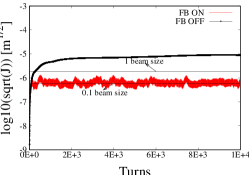
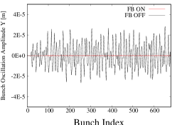
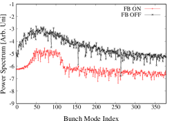

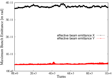
Fig. 8 is calculated with the same parameters as in Fig. 3 by the “weak-strong” model expect that the bunch-by-bunch feedback is turned on. Clearly, the bunch centroid oscillation amplitudes are effectively damped down at least to one order of magnitude smaller compared with the case without bunch-by-bunch feedback. Comparison at the 5000th turn with and without feedback is explicitly shown in Fig. 9. When the bunch-by-bunch feedback is turned on, the maximum bunch action is well maintained around 0.1 rms beam size, Fig. 9a; the bunch oscillations due to beam-ion interaction are well eliminated, Fig. 9b; the power spectrum of of bunch oscillations is roughly one order of magnitude smaller Fig. 9c. The maximum unstable bunch mode does not shift since the intrinsic beam-ion interaction is not violated.
The simulation results given by the “quasi-strong-strong” model are shown in Fig. 10. The bunch centroid oscillation amplitudes are well damped down within 0.1 rms beam size by the bunch-by-bunch feedback system. The effective rms beam emittance are well maintained and only show a tiny increasement after 10 thousand turns. Generally, the effective rms emittance growth can be attributed to two effects. The first one is the coherent bunch centroid oscillation and the second one is the bunch phase space filamention due to the nonlinear Coulomb force. Here, it is stated that, in beam-ion interaction, the coherent bunch centroid oscillation is the main contributor to the effective emittance growth. The effective rms emittance growth from nonlinear space charge is almost inessential.
V Conclusions
In this paper, we have discussed the beam-ion instability and its mitigation by the bunch-by-bunch feedback system. To study the beam-ion interaction consistently, a simulation code is developed including modules of ionization, beam-ion interaction, synchrotron radiation damping, quantum excitation and bunch-by-bunch feedback. As an example, the lattice parameters of HEPS are adopted to show the influence of the beam-ion effect. It is found that in high intensity and ultra-low emittance rings, the beam-ion instability is not a dominant mechanism when the beam current goes high enough. This is because the ions generated are over-focused, get lost between the bunch gaps, and hardly disturb the beam. The beam-ion interaction significantly impacts the beam performance only when ions can be extensively accumulated in certain current region. If the beam-ion instability is too strong to be suppressed by the synchrotron radiation damping, the bunch-by-bunch feedback based on FIR filter technique is proved to be an effective approach to rescue the beam performance.
Still, studies in this paper can be improved to further steps in the future. One point is adding a real self-consistent PIC solver into the code. It is worthy to ensure a real self-consistent process especially when applying the results of codes as guidance for real accelerators. Another point is related to the impedance. As known, an abundant of instabilities can be induced by the impedance. It will be very important to understand how the beam-ion interaction and the impedance interplay with each other. In the future, modules to deal with the impedance and wakefield will be developed to study the complex beam dynamics system and then the ability of feedback system will be re-evaluated.
Acknowledgements.
This work is supported by the Key Research Program of Frontier Sciences CAS (QYZDJ-SSW-SLH001) and NSFC (11775239, 11805217). Special thanks to professor Takeshi Nakamura in Synchrotron Radiation Research Institute in Japan for his helpful discussion on FIR filters.References
- Zimmermann et al. (1997) F. Zimmermann, J. B. Y, and A. C. et. al., “Experiments on the fast beam-ion instability at the als,” (1997).
- Byrd and Chao (1997) J. Byrd and A. e. a. Chao, Physical review letters 79, 79 (1997).
- Kwon et al. (1998) M. Kwon, J. Y. Huang, T.-Y. Lee, I. S. Ko, Y. H. Chin, H. Fukuma, M. Isawa, K. Ohmi, and M. Tobiyama, Phys. Rev. E 57, 6016 (1998).
- Jiang et al. (2010) B. Jiang, G. Xia, L. Han, G. Liu, Z. Dai, and Z. Zhao, Nuclear Instruments and Methods in Physics Research Section A: Accelerators, Spectrometers, Detectors, and Associated Equipment 614, 331 (2010).
- Chatterjee et al. (2014) A. Chatterjee, K. Blaser, M. Ehrlichman, D. Rubin, and J. Shanks, in Proceedings, 5th International Particle Accelerator Conference (IPAC 2014): Dresden, Germany, June 15-20, 2014 (2014) p. TUPRI036.
- Nagaoka et al. (2007) R. Nagaoka, M. P. Level, L. Cassinari, M. E. Couprie, M. Labat, C. Mariette, A. Rodriguez, and R. Sreedharan, in 2007 IEEE Particle Accelerator Conference (PAC) (2007) pp. 2019–2021.
- Raubenheimer and Zimmermann (1995) T. Raubenheimer and F. Zimmermann, Physical Review E 52, 5487 (1995).
- Stupakov et al. (1995) G. Stupakov, T. Raubenheimer, and F. Zimmermann, Physical Review E 52, 5499 (1995).
- Ohmi (1997) K. Ohmi, Phys. Rev. E 55, 7550 (1997).
- Ohmi et al. (2001) K. Ohmi, F. Zimmermann, and E. Perevedentsev, Phys. Rev. E 65, 016502 (2001).
- (11) Chao Li, https://github.com/ChaoLiIHEP/FASTION.
- Jiao et al. (2018) Y. Jiao, G. Xu, X.-H. Cui, Z. Duan, Y.-Y. Guo, P. He, D.-H. Ji, J.-Y. Li, X.-Y. Li, C. Meng, Y.-M. Peng, S.-K. Tian, J.-Q. Wang, N. Wang, Y.-Y. Wei, H.-S. Xu, F. Yan, C.-H. Yu, Y.-L. Zhao, and Q. Qin, Journal of Synchrotron Radiation 25, 1611 (2018).
- Wang et al. (2011) L. Wang, Y. Cai, T. Raubenheimer, and H. Fukuma, Physical Review Special Topics-Accelerators and Beams 14, 084401 (2011).
- Lonza and Schmickler (2016) M. Lonza and H. Schmickler, “Multi-bunch feedback systems,” (2016), arXiv:1601.05258 [physics.acc-ph] .
- Bassetti, M and Erskine, George A (1980) Bassetti, M and Erskine, George A, Closed expression for the electrical field of a two-dimensional Gaussian charge, Tech. Rep. CERN-ISR-TH-80-06. ISR-TH-80-06 (CERN, Geneva, 1980).
- Li et al. (2014) C. Li, Z.-L. Zhang, X. Qi, X.-B. Xu, Y. He, and L. Yang, Chinese Physics C 38, 037005 (2014).
- (17) https://ops.aps.anl.gov/manuals/elegant_latest/elegant.pdf.
- Note (1) The average betatron function is used to estimate the ion trapping condition.
- Zhang et al. (2005) Y. Zhang, K. Ohmi, and L. Chen, Phys. Rev. ST Accel. Beams 8, 074402 (2005).
- Xia and Elsen (2008) G. Xia and E. Elsen, Nuclear Instruments and Methods in Physics Research Section A: Accelerators, Spectrometers, Detectors and Associated Equipment 593, 183 (2008).
- Note (2) Rms emittance reference to the idea orbits.
- Chao (1993) A. W. Chao, Physics of collective beam instabilities in high energy accelerators (Wiley, 1993).
- (23) T. Nakamura, “single-loop muli-dimensional digital feedback by fir filters,” http://acc-web.spring8.or.jp/~nakamura/reports/Feedback_with_FIR_Filter_draft1.pdf.