Hybrid Transceiver Designs via Majorization-Minimization Algorithm Over MIMO Interference Channels
Abstract
The potential of deploying large-scale antenna arrays in future wireless systems has stimulated extensive research on hybrid transceiver designs aiming to approximate the optimal fully-digital schemes with much reduced hardware cost and signal processing complexity. Generally, this hybrid transceiver structure requires a joint design of analog and digital processing to enable both beamsteering and spatial multiplexing gains. In this paper, we develop various weighted mean-square-error minimization (WMMSE) based hybrid transceiver designs over multiple-input multiple-output (MIMO) interference channels at both millimeter wave (mmWave) and microwave frequencies. Firstly, a heuristic joint design of hybrid precoder and combiner using alternating optimization is proposed, in which the majorization-minimization (MM) method is utilized to design the analog precoder and combiner with unit-modulus constraints. It is validated that this scheme achieves the comparable performance to the WMMSE fully-digital solution. To further reduce the complexity, a phase projection based two-stage scheme is proposed to decouple the designs of analog and digital precoder-combiner. Secondly, inspired by the fully-digital solutions based on the block-diagonalization zero-forcing (BD-ZF) and signal-to-leakage-plus-noise ratio (SLNR) criteria, low-complexity MM-based BD-ZF and SLNR hybrid designs are proposed to well approximate the corresponding fully-digital solutions. Thirdly, the partially-connected hybrid structure for reducing system hardware cost and power consumption is considered, for which the MM-based alternating optimization still works. Numerical results demonstrate the similar or superior performance of all the above proposed schemes over the existing benchmarks.
I Introduction
The large-scale antenna array offers a promising technology in future wireless systems to provide ultra high data rate for bandwidth-hungry applications and the large degree of freedoms (DoFs) for eliminating the random effect of wireless fading channels [1, 2]. However, the hardware cost and implementation complexity of deploying a large number of antenna elements by the traditional digital signal processing are huge, because each antenna requires a dedicated radio frequency (RF) chain [3, 4]. As an alternative cost-effective solution, the hybrid transceiver structure with much fewer RF chains than the number of antennas has attracted extensive attention recently, of which the signal processing chain consists of the high-dimensional analog RF precoding/combining for providing the beamsteering gain, followed by the low-dimensional digital baseband precoding/combing mainly for reaping spatial multiplexing gain [5, 6].
For the hybrid transceiver structure, the analog RF processing can be implemented using phase shifters [7], switches [8] and/or lens [9], among which the phase shifter based analog precoding/combining has been widely investigated [10, 11, 12, 13, 14, 15, 16, 17]. Phase shifters can be used to steer transmit and receive beams towards the desired direction by adjusting the phase of RF signals, and thus typically impose constant-modulus constraints on analog precoder and combiner, which makes hybrid transceiver designs more complicated and challenging. It has been revealed that once the number of RF chains reaches twice that of data streams, implying that the number of phase shifters is doubled, the hybrid structure can perfectly realize the optimal fully-digital structure [11]. However, the application with abundant phase shifters is also impractical due to high hardware cost and power consumption. To alleviate this issue, the partially-connected hybrid structure has been proposed for enabling energy-efficient communications at the expense of some performance loss compared to the fully-digital structure [12, 13, 14].
Hybrid transceivers are applicable not only to mmWave communications but also in other lower frequency range [10, 15]. Moreover, the criteria of hybrid designs are diverse, e.g., mean squared error (MSE), capacity and bit error rate (BER). Various hybrid transceiver designs have been conceived for point-to-point MIMO systems [6, 17, 18, 19, 20] and multiuser MIMO systems [15, 21, 22, 23, 24, 25]. The motivation of these designs is to leverage the underlying hybrid structure to achieve the comparable performance to the optimal (near-optimal) fully-digital solution. To this end, existing hybrid designs are mainly classified into two categories.
One category jointly designs hybrid precoder and combiner to approach the fully-digital performance. For example, by exploiting the sparsity of mmWave channels, the orthogonal matching pursuit (OMP) algorithm was used to jointly design hybrid precoder and combiner to approximate the optimal fully-digital solution [6]. Using matrix-monotonic optimization [17], the optimal unconstrained structures of analog precoder and combiner under various design criteria can be proved to be unitary matching with channel. Some heuristic joint hybrid transceiver designs via alternating optimization were also investigated [18, 19, 20]. Specifically, to approximate the optimal fully-digital solution, an alternating minimization method was proposed for hybrid designs based on manifold optimization [18] and local approximation of phase increment [19], respectively. In addition, joint hybrid designs were studied in multiuser scenarios using the minimum MSE (MMSE), WMMSE and BD-ZF fully-digital solutions [21, 22, 23]. For example, in [22] and [23], the OMP algorithm was utilized to jointly construct the hybrid WMMSE precoder and combiner for achieving the performance close to the WMMSE and BD-ZF fully-digital solutions, respectively. However, such approaches generally require the fully-digital precoder to have a closed-form solution, and its applicability in more general scenarios may be limited.
The other category is the two-stage hybrid transceiver design widely used in multiuser MIMO scenarios. In this scheme, the analog precoder and combiner are firstly designed by directly optimizing some performance criterion, such as the effective array gain. Then the digital precoder and combiner are optimized to further improve system performance by eliminating inter-user inference [15, 24, 25]. For example, in [15], the equal gain transmission (EGT) based analog precoder and the discrete Fourier transform (DFT) codebook based analog combiner for each user were proposed to achieve large array gain. To achieve low channel training and feedback overhead, the two-stage hybrid design [24] chooses each user’s analog precoder and combiner from the quantized codebooks to maximize effective channel gain. All the above analog processing schemes can be combined with the low-complexity BD-ZF digital processing [26] to cancel inter-user interference. Although this BD-ZF scheme is easy to implement, it does not consider the influence of noise in the digital precoder design and thus performs poorly at low signal-to-noise ratio (SNR) regime. This fact motivates us to consider an effective digital processing based on the SLNR criterion of [27]. The SLNR-maximization digital processing is more desirable than the BD-ZF criterion in some scenarios with fewer DoFs, i.e., MIMO interference channels [28]. This two-stage scheme can also be extended to the mixed timescale hybrid precoder optimization [29, 30] in which the analog and digital precoders are adaptive to channel statistics and real-time channel state information (CSI), respectively.
In this paper, we consider challenging MIMO interference channels with very few DoFs and develop various hybrid transceiver designs based on the MM method. Since the MM method guarantees stationary convergence and has the desired closed-form solution of each subproblem, it offers an effective tool to address the nonconvex constant-modulus constraints on analog precoder and combiner [31, 32]. Specifically, we propose the MM-based alternating optimization, decoupled two-stage scheme and various low-complexity schemes for hybrid transceiver designs in both mmWave and lower-frequency Rayleigh MIMO interference channels. Additionally, perfect CSI and analog processing with infinite resolution are utilized to provide a theoretical performance upper-bound for practical implementation of all the proposed schemes. Our contributions together with the associated technical challenges are summarized as follows.
-
1.
Joint hybrid transceiver design bypassing the optimal fully-digital Solution. For the -user MIMO interference channel, the joint hybrid WMMSE transceiver design bypassing the near-optimal fully-digital WMMSE solution is studied. This joint design is very challenging since the coupled variables and unit-modulus constraint on the analog precoder and combiner lead to the nonconvex and NP-hard optimization. To tackle this challenge, the MM-based alternating optimization under a practical property of large-scale MIMO is proposed, which guarantees to converge. To further reduce the computational complexity, we also study another phase projection (PP) based two-stage scheme with the decoupled designs of analog and digital precoder and combiner.
-
2.
Low-complexity separate hybrid transceiver designs. Since the suboptimal closed-form fully-digital precoders for each transmit-receive pair can be obtained based on BD-ZF and SLNR maximization (SLNR-Max) criteria, the proposed low-complexity hybrid transceiver designs focus on approximating the BD-ZF and SLNR-Max fully-digital precoders, which also belong to nonconvex optimization. In fact, both these low-complexity designs contain multiple separate hybrid transceiver designs for all transmit-receive pairs, each of which consists of two separate stages. To address this non-convexity, the iterative PP (iterative-PP) based hybrid precoder is firstly designed. Then the corresponding hybrid MMSE combiner is optimized through the MM-based alternating optimization.
-
3.
Low-cost joint hybrid transceiver design. In order to further reduce hardware cost and power consumption, we consider the partially-connected hybrid structure, in which each RF chain at transmitter/receiver is connected to a single non-overlapped subarray. In this context, the MM-based alternating optimization still works and can converge to the stationary solutions for the joint hybrid WMMSE transceiver design.
Notations: The bold-faced lower-case and upper-case letters stand for vectors and matrices, respectively. The transpose, conjugate, Hermitian and inverse operators are denoted by , , and , respectively, while and denote the trace and determinant of , respectively. , and are the identity matrix, the zero matrix and the -dimensional vector with all elements being one, respectively. The block-diagonal matrix with diagonal elements is denoted by . Particularly, it is reduced to when scalar diagonal elements are considered . denotes the th (the th row and th column) element of , and denotes the sub-matrix consisting of the to rows and to columns of , while is the sub-matrix consisting of the to columns of . The th element of is denoted by , and is the sub-vector consists of the th to th elements of . () means that is positive definite (semi-definite), and is the maximum eigenvalue of , while denotes the phase extraction operation in an element-wise manner. The rank of is denoted by . The modulus operator denoted by , is the Euclidean distance, and is the matrix Frobenius norm, while is the expectation operator and is the vectorization of a matrix. is the real part operator and is the Kronecker product operator, while . The words ‘independent and identically distributed’ and ‘with respect to’ are abbreviated as ‘i.i.d.’ and ‘w.r.t.’, respectively.
II System Model
II-A -user MIMO interference channel
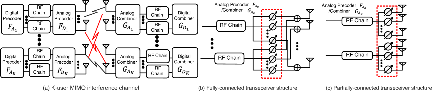
As shown in Fig. 1, we consider a -user MIMO interference channel, where all transmitters and receivers are equipped with hybrid MIMO processor for dealing with multiple data streams. Specifically, the th transmitter equipped with antennas and RF chains sends data streams to the corresponding receiver equipped with antennas and RF chains, where and , . The hybrid MIMO processor at the th transmitter enables the digital baseband precoder , followed by the analog precoder . Similarly, the hybrid MIMO processor at the th receiver consists of an analog RF combiner , followed by a digital combiner . Both and are realized using analog phase shifters with constant modulus, i.e., and , . The transmitted signal by the th transmitter is given by , where denotes the Gaussian encoded information symbols satisfying and with being the maximum transmit power. Under the assumption of quasi-static block-fading MIMO channel, the received signal at the th receiver is written as
| (1) |
where denotes the wireless channel between the th transmitter and th receiver, and is the additive Gaussian noise at the th receiver, which has zero mean vector and covariance matrix . Then the hybrid analog-digital combiner at the th receiver, i.e., , is applied to to obtain the desired output as
| (2) |
The achievable sum rate of this -user MIMO system under Gaussian signaling is given by
| (3) |
where is the covariance matrix of the inter-user interference plus noise at the th receiver, . We aim to jointly design the hybrid precoders and combiners to maximize the achievable sum rate (II-A), which is formulated as
| (7) |
Clearly, the sum rate maximization (7) is nonconvex and NP-hard w.r.t. due to the coupled optimization variables and unit-modulus constraints. Even the optimal fully-digital solution to the problem (7) without the unit-modulus constraint has not been globally addressed yet, and only stationary solution generated from iterative process is available [34]. Therefore, for -user MIMO interference channels, the traditional method of minimizing the Euclidean distance between the hybrid analog-digital precoder and the optimal fully-digital one cannot theoretically guarantee its sum rate performance. In the sequel, using a reasonable assumption on the analog precoder in large-scale MIMO systems, we find an effective joint design of hybrid precoder and combiner to the problem (7) via the MM-based alternating optimization with guaranteed sum rate performance.
Although the proposed alternating optimization procedure achieves the semi closed-form solution to each subproblem, it imposes heavy coordination among all transmit-receive pairs. To further reduce complexity, a two-stage hybrid design is firstly proposed with the decoupled optimization of analog and digital precoder-combiner for each transmit-receive pair. Then, two hybrid designs based on the BD-ZF and SLNR-Max fully-digital precoding are studied, both support the independent hybrid precoder and combiner design. All the above schemes require global CSI at transmitter, which imposes huge training and feedback overhead. To alleviate this problem, we also consider the partially connected hybrid transceiver structure with significantly reduced feedback overhead and hardware cost, to which the proposed alternating optimization is directly applicable and a stationary solution of the problem (7) can be achieved.
II-B Channel model
In our work, two kinds of block-fading channels are adopted, mmWave channels and Rayleigh channels. The first type considers the propagation environment at the mmWave band, which has limited scattering and suffers from several blockage and reduced diffraction, while the other considers the propagation environment with rich scatterers. Moreover, to make the system capacity independent of the scaling of the channel matrix, we use the normalized channel matrix.
For Rayleigh channels, the elements of the channel matrix are i.i.d. complex Gaussian variables with zero mean and unit variance, i.e., , and . For mmWave channels, the extended Salen-Valenzuela geometric model [35] is adopted:
| (8) |
where denotes the number of dominated propagation paths in the channel and is the complex gain of the th path, while and are the angle of arrival (AOA) and angle of departure (AOD) of the th path, respectively. Assume that the uniform linear array (ULA) is deployed at each transmit-receive pair. The transmit and receive array steering vectors can then be expressed as and , respectively, where denotes the signal wavelength and the antenna element spacing is .
III MM-based Joint Hybrid Transceiver Design
III-A Equivalent problem reformulation
To tackle the sum rate maximization (7) effectively, we introduce and , , and reformulate it as an equivalent WMMSE problem [34]:
| (12) |
where we still use and the MSE matrix is defined as
| (13) |
For massive MIMO, the analog precoder design for approximating the near-optimal system performance typically satisfies , , with high probability when [11, 6, 25]. Therefore, we exploit this property and assume that . Then the problem (12) is simplified as
| (17) |
where and is obtained by using in (III-A).
We can jointly optimize the hybrid precoder and combiner by solving (17). Given the other variables, the problem (17) is convex w.r.t. , which can be derived in closed-form
| (18) |
In addition, it is well-known that the optimal digital combiner for simultaneously minimizing all the MSEs of the data streams of the th transmit-receive pair is the Wiener filter:
| (19) |
where . Based on the closed-form solutions (18) and (19), our next task is to find the optimal solution to the problem (17), but (17) is not jointly convex w.r.t. . In Section IV, a MM-based alternating optimization procedure is proposed to find the semi closed-form solution to the problem (17) with guaranteed stationary convergence.
IV Proposed MM-Based Alternating Optimization
IV-A Brief review of MM method
The MM method is an effective optimization tool for solving nonconvex problems. The basic idea is to transform the original nonconvex problem into a sequence of majorized subproblems that can be solved with semi closed-from solutions and guaranteed convergence. The MM method generally consists of two stages, the majorization stage and the minimization stage. In the majorization stage, for a general optimization problem
| (20) |
where is a closed nonempty set. In terms of our work, it can be nonconvex. Our aim is to find a continuous surrogate function , also defined as a majorizer of at , for updating at the th iteration. Mathematically, this is expressed as
| (21) |
The majorizer must satisfy the following conditions to ensure that the MM method converges to a stationary point of the problem (20) [31]:
| (25) |
where is the Boulingand tangent cone [33] of at . It is known that the limit point obtained by minimizing subject to satisfies the stationary condition , . Also, based on (25), the monotonicity of the MM method is manifested by
| (26) |
The interested readers can refer to [31, 32] for more details of the general MM method.
IV-B Proposed MM-based alternating optimization
Our proposed MM-based alternating optimization for the problem (17) is a combination of the block coordinate descent (BCD) and MM methods. To be specific, we first partition the remaining variables into three blocks as , and . The MM method is then utilized to update the blocks and , respectively, with the other blocks fixed. Compared to applying the MM method to the problem (17) with a single complete block, this approach provides more flexibility in designing surrogate functions for better approximating the objective function of the problem (17), leading to faster convergence rate [31].
IV-B1 Semi closed-form digital precoder
Given the fixed , we can rewrite the objective function of the problem (17) by omitting the constant term as
| (27) | ||||
where , , and . Taking the derivative of w.r.t. leads to the semi closed-form digital precoder
| (28) |
where is the dual variable associated with the th transmit power constraint. Define the eigenvalue decomposition (EVD) . Since should satisfy the complementarity slackness condition , if , the optimal ; otherwise, is derived from , where .
IV-B2 Semi closed-form analog precoder
Given , the problem (17) is non-convex on . We need to find an effective majorizer of the objective function of (17) in terms of , , so that a stationary solution for the problem (17) can be obtained using the MM method. According to the identity , the objective function of (17) can be re-expressed as
| (29) |
where , , , and , . It is clearly observed that there is no coupling among in , implying that the designs of , are independent of each other.
Lemma 1.
[32] For any two Hermitian matrices satisfying , a majorizer of the quadratic function at any point is
IV-B3 Semi closed-form analog combiner
Similarly, by fixing , we re-express the objective function of the problem (17) in terms of , as
| (33) |
where , , and . Obviously, is separable w.r.t. . Hence, based on Lemma 1, a majorizer of at is given by
| (34) |
where and . Hence, the majorized problem for optimizing can be simplified as
| (35) |
with the semi closed-form solution
| (36) |
Integrating the solutions (18), (19), (28), (32) and (36) leads to the proposed MM-based alternating optimization for the hybrid transceiver design, which is listed in Algorithm 1.
IV-C Two-stage hybrid transceiver design
Next we propose a two-stage hybrid transceiver design with the decoupled analog and digital precoder-combiner optimization. First, we present a useful property of large-scale MIMO.
Proposition 1.
For large-scale MIMO systems with Rayleigh or mmWave channels, the correlation matrices between different channels and , satisfy
| (37) |
Moreover, define the singular value decompositions (SVDs) . We infer from (37) that the first columns of and the first columns of , are asymptotically orthogonal, i.e.,
| (38) |
Proof.
See Appendix -A. ∎
According to Proposition 1, the desired channel of each transmit-receive pair and the corresponding interference channels are all asymptotically orthogonal, which implies that the inter-user interference can be canceled by the large array effect without loss of MIMO transceiver design freedom. Based on the above discussion, in the first stage, we independently design the analog precoder and combiner of each transmit-receive pair to maximize the effective channel gain, which is beneficial to improve the sum rate. Mathematically, it is formulated as
| (39) |
Note that the problem (IV-C) is still nonconvex. However, for large-scale MIMO systems, the unconstrained optimal solution of the problem (IV-C) is easily derived as [25, 27]
| (40) |
Our goal is to design the unit-modulus analog precoder and combiner to sufficiently approximate the closed-form solution of (40). Hence, the unit-modulus analog precoder is designed so that
| (41) |
Likewise, the unit-modulus analog combiner can also be obtained according to
| (42) |
Both these two problems can be globally solved by PP to yield the closed-form solutions as
| (43) |
In the second digital stage, to further suppress the inter-user interference at all transmit-receive pairs, the WMMSE-based joint optimization of the digital precoder and combiner is still required. By fixing the analog precoder and combiner at the solutions obtained in the first analog stage, a low-dimensional alternating optimization between the digital precoder in (28) and the digital combiner in (19) is performed, which clearly has lower computational complexity than the proposed MM-based alternating optimization of Section IV-B.
This two-stage hybrid design can be regarded as a special case of the MM-based alternating optimization by predetermining the analog precoder and combiner of each transmit-receiver pair as given in (43), and thus only the iterative procedure between the digital precoder and the digital combiner is performed. The performance of the MM-based alternating optimization generally depends on the initial point [34], and we heuristically choose the analog precoder and combiner design of (43) as a initial point due to its potential in harvesting large array gain. The superior sum rate performance of this two-stage hybrid design will be illustrated by the numerical simulations of Section VII.
V Low-Complexity and Low-Cost Hybrid Transceiver Designs
Although the semi closed-form solutions to hybrid transceiver design can be obtained using the above two alternating optimization procedures, they require extensive coordination among all transmit-receive pairs. In this section, we investigate the low-complexity hybrid transceiver designs from the perspectives of decoupling hybrid precoder and combiner designs for each transmit-receive pair and reducing hardware cost, respectively.
V-A BD-ZF hybrid transceiver design
It is well-known that by completely eliminating the inter-user interference, the BD-ZF precoding is a near-optimal scheme for multiuser massive MIMO systems. By considering it for our MIMO interference channels, we firstly propose a low-complexity BD-ZF hybrid transceiver design, in which the number of antennas at each transmitter is larger than the total number of receive antennas, i.e., , . For mmWave channels, this restriction can be relaxed further to , . Specifically, by first defining the leakage channel for the th transmit-receive pair as , , an orthonormal basis for the orthogonal complement of is given by with and . Then the fully-digital BD-ZF precoder at the th transmitter for eliminating both inter-user and intra-data interference can be expressed as
| (44) |
where originates from the SVD with , and is the solution of the following sum rate maximization
| (47) |
It is clear that the optimal solution to the problem (47) has a water-filling structure, i.e., , , where is chosen to satisfy , .
V-A1 Iterative-PP hybrid precoder design
Given the fully-digital BD-ZF precoder (44), we design the hybrid precoder by solving the following optimization problem
| (48) | ||||
where the maximum power transmission is adopted. By introducing the new variables and , , the problem (48) is rewritten as
| (49) |
Although the problem (V-A1) is much simplified compared to the problem (48), it is still challenging to directly design the analog precoder in the unit-modulus space. We resort to an iterative-PP based method with two key ingredients: unconstrained optimal analog precoder and alternating minimization. The unconstrained optimal analog precoder to the problem (V-A1) using majorization theory [27] is summarized in the following proposition.
Proposition 2.
The unconstrained optimal analog precoder to the problem (48) is
| (50) |
where the unitary matrix comes from the SVD . Moreover, both the diagonal matrix and the unitary matrix can be arbitrarily chosen.
Proof.
Define the SVDs , and , where and are the sets of unitary matrices, while are the corresponding diagonal matrices with diagonal elements arranged in a decreasing order. It is observed from (V-A1) that subject to the power constraint is unitarily invariant. In other words, both the unitary matrices and are unconstrained. In addition, observing from , we find that the diagonal matrix actually has no effect on the maximum value of the objective function in (V-A1), which is also applicable to the problem (48). Further by applying [36, B.2. Theorem (Fan,1951)] to the problem (V-A1), the unconstrained optimal analog precoder to the problem (48) is readily derived as (50), where and are arbitrarily chosen. ∎
Based on Proposition 2, we then aim to find an unit-modulus analog precoder with the minimum Euclidean distance to the unconstrained optimal , which is formulated as
| (51) |
Since the diagonal matrix has no effect on the problem (48), we consider the unconstrained diagonal matrix . Although the problem (V-A1) is not jointly convex w.r.t , it is a ‘semi-convex’ problem, in which the closed-form solution of each variable is easily obtained when fixing all the others, thus enabling alternating optimization. Specifically, given and , the optimal analog precoder to the problem (V-A1) can be obtained via PP
| (52) |
By fixing and , after some algebraic manipulations, the optimal diagonal matrix to the problem (V-A1) is designed by solving the optimization
| (53) |
which has the closed-form solution
| (54) |
Finally, for the fixed and , the optimal unitary matrix is given by
| (55) |
where the unitary matrices and come from the SVD .
Through alternating optimization among (52), (54) and (55), the iterative PP-based unit-modulus analog precoder can be finally obtained. Then by applying Lagrangian multiplier method to the problem (48), the optimal digital precoder given is expressed as
| (56) |
Even when the distance between the hybrid precoder and the fully-digital BD-ZF precoder is minimized, we still cannot guarantee the hybrid precoder’s capability of realizing zero inter-user interference, since it may not be exactly located in the null-space of the corresponding leakage channels. However, the effectiveness of the above iterative-PP hybrid precoder design on suppressing the inter-user interference is demonstrated in the following proposition.
Proposition 3.
Proof.
See Appendix -B. ∎
Proposition 3 reveals that in large-scale mmWave scenarios, the above iterative-PP hybrid precoder also achieves the near-zero inter-user interference, like the fully-digital BD-ZF precoder. However, it may not work well in Rayleigh channels due to the following two reasons. The fully-digital BD-ZF precoder with a strict restriction on the numbers of transmit and receive antennas may be infeasible in rich scattering scenarios, especially for a large number of transmit-receive pairs. Also Proposition 3 is not applicable to the channels without sparsity. These facts motivate us to propose another more general low-complexity hybrid precoder design in Section V-B.
V-A2 MM-based hybrid combiner design
Given the hybrid precoder (52) and (56), the MMSE hybrid combiner design is then formulated as
| (58) |
where , and , while the equality (a) holds by following the similar derivations in [6]. Obviously, the problem (V-A2) is more complicated than the problem (48) due to introducing . Fortunately, the proposed MM-based alternating optimization is still applicable, as shown below.
When the analog combiner is fixed, the optimal digital combiner has the closed-form
| (59) |
Given the fixed digital combiner , the MM method is used to tackle the nonconvex problem (V-A2) in terms of by finding an appropriate majorized problem, which is
| (60) |
where , and . The semi closed-form solution to the problem (60) is given by
| (61) |
Due to the iterative nature between (59) and (61), the hybrid combiner obtained better matches with the iterative-PP hybrid precoder in (52) and (56).
By integrating the sparse recovery problems (48) and (V-A2), the proposed BD-ZF hybrid transceiver design is summarized in Algorithm 2.
V-B SLNR-Max hybrid transceiver design
The drawbacks of the BD-ZF technique are the restriction on the number of antennas and the noise enhancement. We consider alternative design based on SLNR maximization. The SLNR of the th transmitter is defined as the ratio of the received signal power at the desired th receiver to the interference (leakage) at other receivers plus noise power [27]
| (62) |
Then the SLNR-Max fully-digital precoder for each transmit-receiver pair is designed as [27]
| (63) |
Define the generalized EVD for the matrix pencil as
| (66) |
where the columns of and the diagonal elements of are the generalized eigenvectors and eigenvalues, respectively. Then the optimal SLNR-Max fully-digital precoder is given by
| (67) |
Similarly to the BD-ZF hybrid design, we formulate the SLNR-Max hybrid design by minimizing the Euclidean distance between (67) and the hybrid counterpart as
| (68) |
The problem (V-B) can be effectively solved following the same approach of solving the problem (48) by replacing with , i.e., the MM-based alternating optimization is applicable. Additionally, once the SLNR-Max hybrid precoder for each transmit-receive pair is obtained, the corresponding MMSE hybrid combiner design can be independently carried out as in (V-A2). This SLNR-Max hybrid design is also summarized in Algorithm 2.
V-C Partially-connected hybrid transceiver structure
In the partially-connected structure, each RF chain at both ends is only connected with a part of the antenna array. Specifically, at the th transmitter (receiver), each RF chain is only connected with () antennas, and thus the analog precoder and combiner , , can be expressed by the following block matrices
| (69) |
where the unit-modulus entries , , , and , , , are imposed. Benefited from the block diagonal structures of the analog precoder and combiner, the MM-based alternating optimization can be directly applied to the WMMSE problem (12) to obtain the locally optimal solution without requiring the approximation on analog precoder as in Section IV. More importantly, due to the sparsity of the partially-connected structure, the MM-based analog precoder and combiner designs exhibit much lower complexity than that of Section III.
V-C1 Semi closed-form digital precoder
V-C2 Semi closed-form analog precoder
Given , we firstly define the following auxiliary parameters for optimizing the partially-connected analog precoder , which are
| (80) |
Following the similar derivations of (31), the partially-connected analog precoder for each transmit-receive pair is independently designed as
| (81) |
V-C3 Semi closed-form analog combiner
Similarly to solving (35), by defining
| (89) |
| (93) |
the independent design of partially-connected analog combiner for each transmit-receive pair can be formulated as
| (94) |
Also, the majorized counterpart of the problem (V-C3) at can be expressed as
| (95) |
where , and the semi closed-form solution is derived as
| (96) |
V-C4 Semi closed-form digital combiner and weighting matrix
The optimal digital combiner for the WMMSE problem (12) under this partially-connected structure is also Wiener filter, which has the same form as (19). Moreover, the optimal weighing matrix can be similarly derived as (18).
Observing from (82) and (95) that this partially-connected structure simplifies the analog precoder and combiner design due to the reduced number of optimization variables, and also makes the proposed MM-based alternating optimization directly applicable without the assumption in large-scale MIMO regime. In a nutshell, the proposed MM-based hybrid design is well suited for this partially-connected structure.
VI Convergence of the Proposed Algorithms and Complexity Analysis
We firstly study the convergence of the proposed MM-based alternating optimization (MM-Alt-Opt). It is obvious that the objective function of the problem (17) is continuously differentiable and the constraint set is closed, bounded and separable in terms of optimization variables , . In fact, the proposed MM-Alt-Opt for solving the problem (17) is a combination of the BCD and MM methods, in which the uniquely optimal solutions of the blocks , and are available and the stationary solutions of the blocks and are obtained using the MM method [31]. Referring to [37, Theorem 4.3], since at least the stationary point for each block update is guaranteed, the proposed MM-Alt-Opt converges to a stationary point of the problem (17). However, due to the adopted approximation on analog precoder, i.e., , in (17), this stationary point is actually a suboptimal solution to the original sum rate maximization problem (7), but with an asymptotically optimal performance for large-scale MIMO regime according to Proposition 1.
Next we analyze the computational complexity of the proposed MM-Alt-Opt, PP-based two-stage hybrid design (Hybrid PP-Two-Stage), BD-ZF and SLNR-Max based hybrid designs ( Hybrid BD-ZF/SLNR-Max), in comparison with the classical OMP scheme [6]. To simplify the analysis, we consider that , and , . In the OMP scheme, the length of codebooks for analog precoder (combiner) design is set to , and is assumed. We focus on the complexity of major computational steps, in which the low-order terms are omitted, and then the total complexity is added.
Let and be the numbers of outer and inner iterations, respectively, for the MM-based methods, including the MM-Alt-Opt and Hybrid BD-ZF/SLNR-Max. Observe from Algorithm 1 that in one outer iteration of the MM-Alt-Opt, the computational cost is mainly from the MM-based analog precoder design with the complexity on the order of per transmit-receive pair. The total complexity of the MM-Alt-Opt is obviously linear w.r.t. the number of outer iterations and the number of communication pairs . The similar analysis is applicable to the partially-connected hybrid transceiver case (Hybrid ParTxRx). While for the Hybrid PP-Two-Stage, the complexity primarily comes from the selection of analog precoder and combiner based on the SVD of channel matrix for each transmit-receive pair. The complexity of designing and , which involves an iterative loop with iterations, is much smaller by comparison. This yields the total complexity of . For the Hybrid BD-ZF/SLNR-Max, by defining as the number of iterations for the iterative-PP method, the hybrid precoder design has the complexity , while the MM-based analog combiner design has the complexity . Hence the total complexity of this scheme is for the large . The OMP scheme involves an exhaustive search for both analog precoder and combiner from the predefined codebooks and large-scale matrix multiplication, yielding the total complexity , where is the number of iterations for finding the WMMSE digital precoder and combiner.
VII Simulation Results
Unless otherwise stated, transceiver pairs are used. Each transmitter deploys antennas with RF chains to send data streams to its receiver, which has antennas and RF chains. The RF phase shifters with infinite resolution are assumed. Both the Rayleigh and mmWave channels are considered. For the normalized Rayleigh channel, the elements of all channel matrices are distributed according to . For the normalized mmWave channel, the propagation environment with scatters, , is considered, in which the AOA and AOD of each path are uniformly distributed in , while the pathloss factors , , with obeying . By assuming the same transmit power and the same noise power at all transmitters and receivers, respectively, the received SNR becomes . All the results are obtained by averaging over 100 channel realizations.
In this work, we propose various hybrid transceiver designs, including the MM-Alt-Opt, the Hybrid PP-Two-Stage, the Hybrid BD-ZF/SLNR-Max, and the partially-connected hybrid structure of Hybrid-ParTxRx. In fact, there is another scheme which only considers the partially-connected hybrid structure at transmitter, and we call this scheme Hybrid-ParTx. The sum rate performance of these proposed designs are compared with that of the following baselines:
Hybrid OMP [6]: The sparse reconstruction of the hybrid precoder and combiner of each transmit-receive pair is realized from the fully-digital precoder and MMSE combiner as well as predetermined codebook . The analog beamforming codebook used consists of the array steering vectors (the left/right singular vectors with phase mapping) of the desired mmWave (Rayleigh) channel. In particular, three baselines, called Hybrid OMP-WMMSE, Hybrid OMP-ZF and Hybrid OMP-SLNR, are adopted according to three different fully-digital precoders based on the WMMSE, BD-ZF and SLNR-Max criteria, respectively.
Hybrid EGT-DFT Two-Stage [15]: The EGT based analog precoder and DFT based analog combiner harvest the large array gain in the first analog stage, and the inter-user interference elimination is left to the second digital stage.
Hybrid ParTx-SDR/Hybrid ParTxRx-SDR [18]: First the Euclidean distance between the partially-connected hybrid precoder and the fully-digital WMMSE precoder is minimized in which the iterative procedure between the semidefinite relaxation (SDR) based digital precoder and the PP-based analog precoder is performed. Then the MM-based hybrid combiner designs under the fully connected and partially-connected receiver structures are performed, corresponding to Hybrid ParTx-SDR and Hybrid ParTxRx-SDR, respectively.
Analog-only beamsteering [24]: Only analog beamforming strategies at both ends are considered to align transmit and receive beams of each transceiver pair for maximizing array gain. The inter-user interference elimination is not involved.
Moreover, the near-optimal fully-digital schemes based on the criteria of WMMSE, BD-ZF and SLNR-Max (Fully-Digital-WMMSE, Fully-Digital-ZF and Fully-Digital-SLNR) are adopted as the corresponding upper-bound benchmarks.
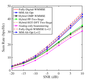
Fig. 2 compares the sum rate performance versus SNR in the mmWave channel achieved by the MM-Alt-Opt and Hybrid PP-Two-Stage with those of the three benchmarks, using the Fully-Digital-WMMSE as the upper bound. It can be seen from Fig. 2 that the sum rate of our MM-Alt-Opt is very close to the optimal Fully-Digital-WMMSE, confirming that it is near-optimal. Benefited from its iterative nature, the MM-Alt-Opt clearly outperforms the Hybrid PP-Two-Stage with one-shot approximation for analog precoder and combiner design. Also the Hybrid PP-Two-Stage achieves a similar performance to the Hybrid OMP-WMMSE at low SNR region, but slightly better performance at high SNR region. More importantly, the Hybrid PP-Two-Stage does not require the WMMSE fully-digital solution and has much lower-complexity than the Hybrid OMP-WMMSE. Since the inter-user interference elimination is not considered in the Analog-only beamsteering, its performance is the worst. In addition, when a larger number of scatters is considered, i.e., , the MM-Alt-Opt still performs almost as good as the Fully-Digital-WMMSE, both having slightly higher sum rate compared to the case of .
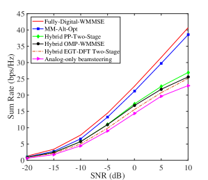
Next, we carry the same comparison in the Rayleigh scenario, and the results are shown in Fig. 3. Observe that the sum rate gap between the optimal Fully-Digital-WMMSE and the MM-Alt-Opt is larger than in the mmWave channel. The reason is that the approximation adopted in the MM-Alt-Opt is less accurate in the Rayleigh case.
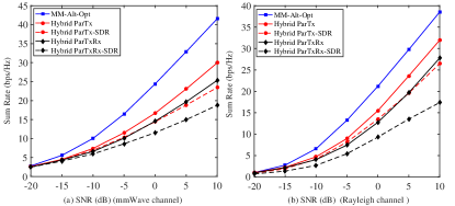
From Fig. 4, it can be seen that the MM-Alt-Opt considerably outperforms the Hybrid-ParTx in both the mmWave and Rayleigh cases, since the inter-user interference cannot be effectively suppressed by the Hybrid-ParTx with its much reduced design freedom in analog precoder. Similarly, the Hybrid-ParTx has better sum rate performance than the Hybrid-ParTxRx, since the latter has the further much reduced design freedom in analog combiner. Also, observe from Fig. 4 that the proposed Hybrid-ParTx outperforms its corresponding benchmark Hybrid ParTx-SDR, while the Hybrid-ParTxRx outperforms its related baseline Hybrid ParTxRx-SDR.
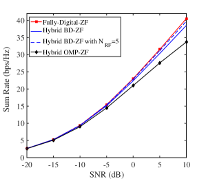
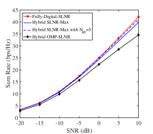
Fig. 5 compares the sum rate performance of the proposed Hybrid BD-ZF and the baseline Hybrid OMP-ZF, using the Fully-Digital-ZF solution as the upper bound. Observe that the sum rate of the Hybrid BD-ZF is close to that of the full-digital BD-ZF solution, especially when one extra RF, i.e., , is considered. Moreover, the proposed hybrid BD-ZF clearly achieves higher sum rate than the hybrid OMP-ZF baseline, because its iterative nature enables the hybrid precoder to better approximate the fully-digital solution at the expense of higher computational complexity. Furthermore, Fig. 6 shows the sum rates achieved by the proposed Hybrid SLNR-Max and the baseline Hybrid-OMP-SLNR versus SNR in the mmWave channel, using the Fully-Digital-SLNR as the upper bound. Clearly, Fig. 6 presents similar comparison results among the three schemes to Fig. 5.
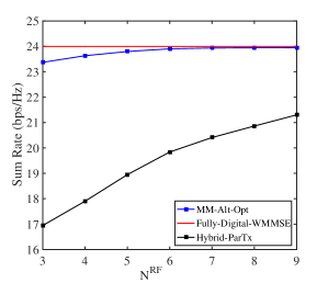
Fig. 7 compares the sum rate performance versus the number of RF chains in the mmWave channel achieved by the proposed MM-Alt-Opt and hybrid-ParTx as well as the optimal Fully-Digital-WMMSE. For the hybrid-ParTx, each of the first RF chains is connected with transmit antennas, while the last RF chain is connected with antennas. It has been shown in [11] that when , there exists a globally optimal hybrid precoder and combiner design, which perfectly reconstructs the fully-digital precoder and combiner, yielding the same sum rate performance. Observe from Fig. 7 that almost identical performance are attained by both the Fully-Digital-WMMSE and the MM-Alt-Opt when . Obviously, the Hybrid-ParTx cannot perfectly reconstruct the fully-digital design due to the reduced design freedom of analog precoder, and the achievable sum rate of the Hybrid-ParTx increases with mainly owing to the increased design freedom of digital precoder.
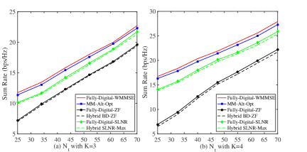
Finally, Fig. 8 depicts the sum rates as functions of the number of transmit antennas in the mmWave channel achieved by the proposed MM-Alt-Opt, Hybrid BD-ZF and Hybrid SLNR-Max, in comparison with their corresponding optimal Fully-Digital-WMMSE, Fully-Digital-ZF and Fully-Digital-SLNR designs, respectively. The results of Fig. 8 confirm that the MM-Alt-Opt, Hybrid BD-ZF and Hybrid SLNR-Max designs are all closed to their respective fully-digital solutions. Obviously, the achievable sum rates of all the schemes increase with owing to the increased spatial degrees of freedom. Also, the MM-Alt-Opt outperforms the Hybrid SLNR-Max, while the Hybrid SLNR-Max has better sum rate than the Hybrid BD-ZF.
VIII Conclusions
This paper has investigated various hybrid transceiver designs for sum rate maximization in both the mmWave and Rayleigh -user MIMO interference channels. First, bypassing the near-optimal WMMSE fully-digital solution, we have jointly designed hybrid precoder and combiner in an alternating manner, in which the MM method is used to design the analog precoder and combiner. Moreover, a PP-based two-stage scheme has been proposed to decouple the design of analog and digital precoder (combiner), leading to lower complexity. Second, with the aid of the easy-to-implement fully-digital precoder, the low-complexity BD-ZF and SLNR-Max hybrid schemes have been studied, which focus on approximating the hybrid precoders to the fully-digital solutions derived according to the BD-ZF and SLNR criteria, respectively. Third, the partially-connected transceiver structure has been considered to reduce the system hardware cost and complexity, to which the MM-based alternating optimization is applicable. Numerical results have demonstrated the effectiveness of all our proposed hybrid transceiver designs, and they have shown that the sum rate performance of all our proposed hybrid designs are close or superior to those of the existing benchmarks. Our future research will study all the proposed hybrid designs implemented with finite resolution phase shifters and/or with limited channel feedback.
-A Proof of Proposition 1
Proof.
The detailed proof of the equality (37) has been given in [25]. We directly use it to validate the equality (1). Firstly, recalling , , we have
| (97) |
where . Since , , are unitary, we have
| (98) |
Let be the th element of the matrix with and . Then, the th element of the matrix can be expressed as . Since the singular values , , are nonzero when , we readily conclude that the equality (98) holds if and only if , , which leads to (1). This completes the proof. ∎
-B Proof of Proposition 3
Proof.
Recalling the mmWave channel model (8), we have
| (99) |
where , and . Note that and , are implied. Referring to [6], when , the array steering vectors , , are linearly independent and asymptotically orthogonal with probability one, i.e., , , and , , which implies that in large-scale mmWave MIMO regime, the array response matrix can be approximated to the right singular matrix of . Furthermore, by recalling (44) and exploiting the equality (1), the fully-digital BD-ZF precoder can be re-expressed as
| (100) |
where and is determined by solving the problem (47). Obviously, the matrix with unit-modulus elements can be realized by RF phase shifters, so that the proposed iterative-PP analog precoder in (52) is easily obtained as when . Correspondingly, the optimal digital precoder is readily derived as . Using the above hybrid precoder design of the th transmitter, the resultant interference at the th receiver, where , satisfies
| (101) | ||||
where the last equality holds by recalling (1). This completes the proof. ∎
References
- [1] L. Lu, et al., “An overview of massive MIMO: Benefits and challenges,” IEEE J. Sel. Topics Signal Process., vol. 8, no. 5, pp. 742–758, Oct. 2014.
- [2] F. Rusek, et al., “Scaling up MIMO: Opportunities and challenges with very large arrays,” IEEE Signal Process. Mag., vol. 30, no. 1, pp. 40–60, Jan. 2013.
- [3] W. Roh, et al., “Millimeter-wave beamforming as an enabling technology for 5G cellular communications: Theoretical feasibility and prototype results,” IEEE Commun. Mag., vol. 52, no. 2, pp. 106–113, Feb. 2014.
- [4] J. Hoydis, S. Ten Brink, and M. Debbah, “Massive MIMO in the UL/DL of cellular networks: How many antennas do we need?” IEEE J. Sel. Areas Commun., vol. 31, no. 2, pp. 160–171, Feb. 2013.
- [5] A. F. Molisch, et al., “Hybrid beamforming for massive MIMO: A survey,” IEEE Commun. Mag., vol. 55, no. 9, pp. 134–141, Sep. 2017.
- [6] O. El Ayach, et al., “Spatially sparse precoding in millimeter wave MIMO systems,” IEEE Trans. Wireless Commun., vol. 13, no. 3, pp. 1499–1513, Mar. 2014.
- [7] G. M. Rebeiz, G. L. Tan, and J. S. Hayden, “RF MEMS phase shifters: Design and applications,” IEEE Microw. Mag., vol. 3, no. 2, pp. 72–81, Jun. 2002.
- [8] R. Méndez Rial, et al., “Hybrid MIMO architectures for millimeter wave communications: Phase shifters or switches?” IEEE Access, vol. 4, pp. 247–267, Jan. 2016.
- [9] Y. Zeng, R. Zhang, and Z. N. Chen, “Electromagnetic lens-focusing antenna enabled massive MIMO: Performance improvement and cost reduction,” IEEE J. Sel. Areas Commun., vol. 32, no. 6, pp. 1194–1206, Jun. 2014.
- [10] L. Liang, W. Xu, and X. Dong, “Low-complexity hybrid precoding in massive multiuser MIMO systems,” IEEE Wireless Commun. Lett., vol. 3, no. 6, pp. 653–656, Dec. 2014.
- [11] F. Sohrabi and W. Yu, “Hybrid digital and analog beamforming design for large-scale antenna arrays,” IEEE J. Sel. Topics Signal Process., vol. 10, no. 3, pp. 501–513, Apr. 2016.
- [12] F. Sohrabi and W. Yu, “Hybrid analog and digital beamforming for mmwave OFDM large-scale antenna arrays,” IEEE J. Sel. Areas Commun., vol. 35, no. 7, pp. 1432–1443, Jul. 2017.
- [13] J. Singh and S. Ramakrishna, “On the feasibility of codebook-based beamforming in millimeter wave systems with multiple antenna arrays,” IEEE Trans. Wireless Commun., vol. 14, no. 5, pp. 2670–2683, May 2015.
- [14] W. Liu, et al., “Partially-activated conjugate beamforming for LoS massive MIMO communications,” IEEE Access, vol. 6, pp. 56504–56513, Oct. 2018.
- [15] W. Ni and X. Dong, “Hybrid block diagonalization for massive multiuser MIMO systems,” IEEE Trans. Commun., vol. 64, no. 1, pp. 201–211, Jan. 2016.
- [16] Z. Zhou, N. Ge, Z. Wang, and S. Chen, “Hardware-efficient hybrid precoding for millimeter wave systems with multi-feed reflectarrays,” IEEE Access, vol. 6, pp. 6795–6806, Mar. 2018.
- [17] C. Xing, et al., “A framework on hybrid MIMO transceiver design based on matrix-monotonic optimization,” IEEE Trans. Signal Process., vol. 67, no. 13, pp. 3531–3546, Jul. 2019.
- [18] X. Yu, J. C. Shen, J. Zhang, and K. B. Letaief, “Alternating minimization algorithms for hybrid precoding in millimeter wave MIMO systems,” IEEE J. Sel. Topics Signal Process., vol. 10, no. 3, pp. 485–500, Apr. 2016.
- [19] W. Ni, X. Dong, and W. S. Lu, “Near-optimal hybrid processing for massive MIMO systems via matrix decomposition,” IEEE Trans. Signal Process., vol. 65, no. 15, pp. 3922–3933, Aug. 2017.
- [20] C. E. Chen, “An iterative hybrid transceiver design algorithm for millimeter wave MIMO systems,” IEEE Wireless Commun. Lett., vol. 4, no. 3, pp. 285–288, Jun. 2015.
- [21] M. Kim and Y. H. Lee, “MSE-based hybrid RF/baseband processing for millimeter-wave communication systems in MIMO interference channels,” IEEE Trans. Veh. Techno., vol. 64, no. 6, pp. 2714–2720, Jun. 2015.
- [22] D. H. Nguyen, L. B. Le, T. Le-Ngoc, and R. W. Heath, “Hybrid MMSE precoding and combining designs for mmwave multiuser systems,” IEEE Access, vol. 5, pp. 19167–19181, Sep. 2017.
- [23] R. Rajashekar and L. Hanzo, “Iterative matrix decomposition aided block diagonalization for mm-wave multiuser MIMO systems,” IEEE Trans. Wireless Commun., vol. 16, no. 3, pp. 1372–1384, Mar. 2017.
- [24] A. Alkhateeb, G. Leus, and R. W. Heath, “Limited feedback hybrid precoding for multi-user millimeter wave systems,” IEEE Trans. Wireless Commun., vol. 14, no. 11, pp. 6481–6494, Nov. 2015.
- [25] X. Wu, D. Liu, and F. Yin, “Hybrid beamforming for multi-user massive MIMO systems,” IEEE Trans. Commun., vol. 66, no. 9, pp. 3879–3891, Sep. 2018.
- [26] Q. H. Spencer, A. L. Swindlehurst, and M. Haardt, “Zero-forcing methods for downlink spatial multiplexing in multiuser MIMO channels,” IEEE Trans. Signal Process., vol. 52, no. 2, pp. 461–471, Feb. 2004.
- [27] M. Sadek, A. Tarighat, and A. H. Sayed, “A leakage-based precoding scheme for downlink multi-user MIMO channels,” IEEE Trans. Wireless Commun., vol. 6, no. 5, pp. 1711–1721, May 2007.
- [28] P. Cheng, M. Tao, and W. Zhang, “A new SLNR-based linear precoding for downlink multi-user multi-stream MIMO systems,” IEEE Commun. Lett., vol. 14, no. 11, pp. 1008–1010, Nov. 2010.
- [29] A. Liu and V. Lau, “Phase only RF precoding for massive MIMO systems with limited RF chains,” IEEE Trans. Signal Process., vol. 62, no. 17, pp. 4505–4515, Sep. 2014.
- [30] A. Liu and V. K. Lau, “Two-stage subspace constrained precoding in massive MIMO cellular systems,” IEEE Trans. Wireless Commun., vol. 14, no. 6, pp. 3271–3279, Jun. 2015.
- [31] Y. Sun, P. Babu, and D. P. Palomar, “Majorization-minimization algorithms in signal processing, communications, and machine learning,” IEEE Trans. Signal Process., vol. 65, no. 3, pp. 794–816, Feb. 2017.
- [32] L. Wu, P. Babu, and D. P. Palomar, “Transmit waveform/receive filter design for MIMO radar with multiple waveform constraints,” IEEE Trans. Signal Process., vol. 66, no. 6, pp. 1526–1540, Mar. 2018.
- [33] J. Pang,“Partially B-regular optimization and equilibrium problems,” Math. Oper. Res., vol. 32, no. 3, pp. 687–699, 2007.
- [34] Q. Shi, M. Razaviyayn, Z. Q. Luo, and C. He, “An iteratively weighted MMSE approach to distributed sum-utility maximization for a MIMO interfering broadcast channel,” IEEE Trans. Signal Process., vol. 59, no. 9, pp. 4331–4340, Sep. 2011.
- [35] J. W. Wallace and M. A. Jensen, “Modeling the indoor MIMO wireless channel,” IEEE Trans. Antennas Propag., vol. 50, no. 5, pp. 591–599, May 2002.
- [36] A. W. Marshall, I. Olkin, and B. C. Arnold, Inequalities: Theory of Majorization and Its Applications. Springer-Verlag: New York, 2011.
- [37] M. W. Jacobson and J. A. Fessler, “An expanded theoretical treatment of iteration-dependent majorize-minimize algorithms,” IEEE Trans. Image Process., vol. 16, no. 10, pp. 2411–2422, Oct. 2007.