How to puncture a biomembrane: elastic versus entropic rupture
Abstract
A very common strategy to penetrate the cell membrane and access the internal compartment, consists of using sharp tips or nano needles. However recent experiments of cell penetration by atomic force microscopy tips show, contrary to expectations, a weak dependence of penetration force on the curvature of the tip. Using molecular dynamics simulations and analytical arguments, here we show that membrane disruption can be driven either by elastic or entropic forces depending on the membrane size. Our findings have potentially relevant implications in tissue engineering and drug delivery, as they help assessing the effectiveness of the most common membranes penetration methods.
Lipid membranes are among the most versatile components of the cell Alberts et al. (2002); Gennis (1989). On the one hand, they act as scaffolds for countless biochemical reactions involving membrane-associated proteins, ribosomes etc. On the other hand, they protect the internal organelles from mechanical and chemical stimuli, by confining the cytoplasm and keeping in-and-out trafficking under strict regulation. Gaining access to the interior of the cell by penetrating the membrane is, therefore, of fundamental importance for many biological processes and applications such as electrical recording Dipalo et al. (2018); Tian and Lieber (2019), drug and bio-molecular delivery Ma et al. (2012); Xie et al. (2012); Chen et al. (2019).
Common strategies to investigate cell membrane penetration rely on atomic force microscopy (AFM) and nanowires arrays, complemented by theoretical models based on continuous elasticity Xie et al. (2013, 2015). In the case of cell penetration by sharp tips, these models predict a strong dependence of the penetration force on the radius of curvature of the tip: the lower the radius of curvature the higher the local pressure, making penetration likely even at low forces. This is consistent with everyday-life experience: to punch a balloon one would rather use a sharp pin than a blunt one. Yet, recent results from AFM experiments show a radically different and unexpected behavior. The force exerted to penetrate the cell depends only weakly on the radius of curvature of the tip over more than one order of magnitude Angle et al. (2014); Obataya et al. (2005). In particular, Angle et al. Angle et al. (2014) have demonstrated that penetration forces measured with tips having radius of curvature nm and nm differ only by 40%, despite the corresponding pressure changes by more than a factor twohundred! Similarly, Obataya et al. Obataya et al. (2005) reported larger penetration force for pyramidal tips than for cylindrical ones, regardless the obvious difference in sharpness.
In this Letter we aim at clarifying this apparent contradiction. Using molecular dynamics simulations (MD) and Helfrich’s continuous theory, we demonstrate that the rupture of a lipid membrane indented by a microscopic tip originates from two types of forces: short-ranged contact forces, exerted by the tip upon the elastically deformed membrane, and long-ranged entropic forces, resulting from the confinement of the thermal undulations. Depending on the size of the membrane, hence the amplitude of thermal undulations, entropic rupture can occur before indentation, thus making the sharpness of the tip unimportant.
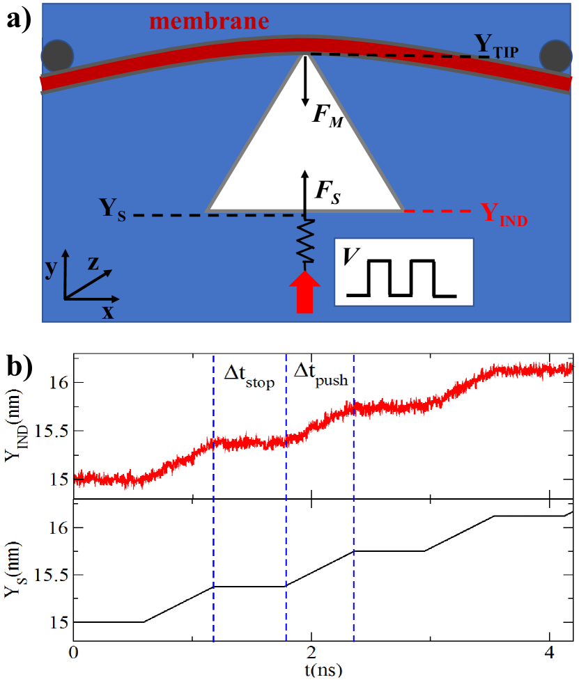
Our MD simulations are based on a two-dimensional coarse-grained model, in which lipids are represented as a single hydrophilic Lennard-Jones (L-J) bead (i.e. the head) connected to a chain of five hydrophobic L-J beads (i.e. the tail). The beads have diameter nm. Water molecules are also modeled as L-J beads Venturoli et al. (2006); Ayton et al. (2006). When lipid molecules are randomly dispersed in water they self-assemble in the form of a bilayer, with the hydrophilic heads pointing toward water and the tails clustering together to shield from the solvent SI . The membrane is tensionless and its average conformation is initially straight. The area expansion modulus, , and the bending stiffness, , of this model bilayer have been already estimated elsewhere Capozza et al. (2018). The indenter consists of a rigid cluster of repulsive L-J particles connected to a spring of stiffness . From the compression/elongation of the spring we obtain a direct measure of the force on the indenter (Fig.1a). Evidently, our two-dimensional model cannot reproduce all the processes that occur in three-dimensional systems, such as lipid diffusion through the membrane, but represents a good compromise between the accuracy and computational cost and allows a statistical analysis of the results. The maximum size of our system is nm and periodic boundary conditions are applied.
As the indenter approaches the lipids, it experiences a force , due to the interaction with the membrane, and a drag force from the surrounding fluid. In order to quantify the latter, we have calculated the time-averaged force on the indenter as a function of its velocity, , without the membrane (for detail see Ref. SI ). In the range of parameters explored, the behavior of versus is linear to a good approximation. This allows us to estimate the viscosity as Pa s. More importantly, this calculation demonstrates that, even at the lowest velocity value accessible to our simulations, the drag force is pN. This is comparable with the membrane tensile strength Capozza et al. (2018), thus implies that the drag force exerted by the solvent is never negligible. In order to circumvent these limitations and decouple from , we opted for a stepwise loading protocol. We first pull the spring at constant speed, m/s, for a time ns and then we pause for a time interval ns (Fig.1b). During we measure the time-averaged force experienced by the spring . Fig.1b shows a comparison between the position of the indenter, , and the spring, , versus time. The data demonstrate that our protocol is quasi-static and that, during the time interval , the indenter fluctuates around its equilibrium position, thus validating the approximation .
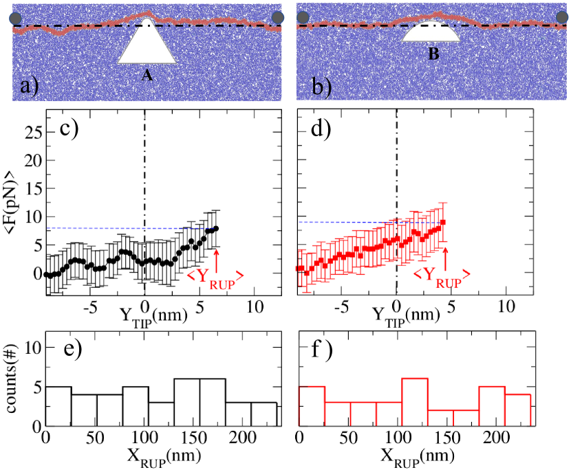
In order to investigate how the sharpness of the indenter affects the penetration force, we have considered two indeters, labeled and , having radius of curvature nm and nm respectively. The membrane is kept in place by a pair of cylindrical posts held at a distance from each other (see Fig.2a,b). In this configuration, resembling the set-up of a pore-spanning membrane loaded by an AFM tip Steltenkamp et al. (2006); Mey et al. (2009), the system is free to vibrate as a result of thermal motion of the lipids. Fig.2c,d shows the force experienced by the indenter as a function of its vertical position . The data points and error bars are obtained by averaging over 20 different simulations. Remarkably, even when the tip of the indenter is far from the membrane (i.e. nm, well below the dashed line in Fig.2a,b indicating the membrane straight profile), we detect a measurable force as reported experimentally Alessandrini and Facci (2012). Since for there are no other forces acting on the membrane except the contact force exerted by the indenter and those arising from thermal fluctuations, we ascribe the origin to the signal measured in the absence of contact to entropic forces.
In addition to the force, we measure the position point of rupture: . In particular, the average vertical position of the rupture point, corresponding to maximal indentation depth, is marked by a red arrow in Fig.2c,d. These results clearly show that both the maximal indentation depth and the rupture force are comparable for the two indenters, despite the difference in sharpness and consistent with AFM experiments Angle et al. (2014); Obataya et al. (2005, 2005). As a further demonstration of the irrelevance of the tip radius of curvature, we report in Fig. 2e,f the distribution of the horizontal position of the point of rupture for the and tip. Even for the sharper tip, the membrane breaks at a random location, uniformly distributed between the two blocking posts and not at the center, as one would expect by viewing the membrane as an elastic sheet punctured in the middle by a sharp pin.
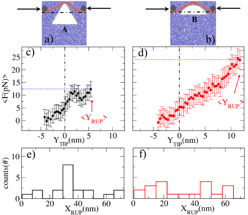
The situation drastically changes when the system size is reduced to nm, as shown in Fig.3. The maximal indentation depth and the rupture force are prominently smaller for the sharper tip than for the flatter tip, as expected from elastic materials. Furthermore the distribution of , shown in Fig.3e,f, indicates now a preference towards the center in the case of the tip. These results demonstrate that, upon reducing the thermal undulations of the membrane by shortening the system size , the system crossovers from an entropic to an elastic regime, in which rupture results as a direct consequence of the applied pressure. A similar trend is also obtained by keeping the system size to nm but moving closer the blocking posts at distance nm (see Ref. SI for more details).
Entropic forces in confined lipid membranes, also known as undulation forces, have been predicted four decades ago by Helfrich in the context of multilayered structures Helfrich (1978) and later investigated experimentally and theoretically Abillon and Perez (1990); Israelachvili (2011); Lindahl and Edholm (2000); Ayton et al. (2006). Analogously to other types of entropic forces, undulation forces arises when spatial confinement limits the fluctuations of the membranes, thus leading to a decrease in entropy. In order to illustrate this concept, in the following we calculate the force experienced by an effectively one-dimensional membrane loaded by an infinitesimally sharp tip. Under the assumption of small fluctuations, the membrane’s free-energy can be expressed as (see e.g. Ref. Israelachvili (2011)):
| (1) |
where is the height of the membrane above the axis of standard Cartesian frame, and are, respectively, the effective bending stiffness and surface tension and the prime indicates differentiation with respect to .
First, we show that the thermal undulations of the membrane increases with the system size, thus rendering large membranes more prone to rupture than smaller membranes. This is readily done upon expanding in Fourier modes, i.e. , with . Now, in our system and , with the typical radius of curvature of the membrane. Then, approximating Eq. (1) as and using the equipartion theorem yields: , from which
| (2) |
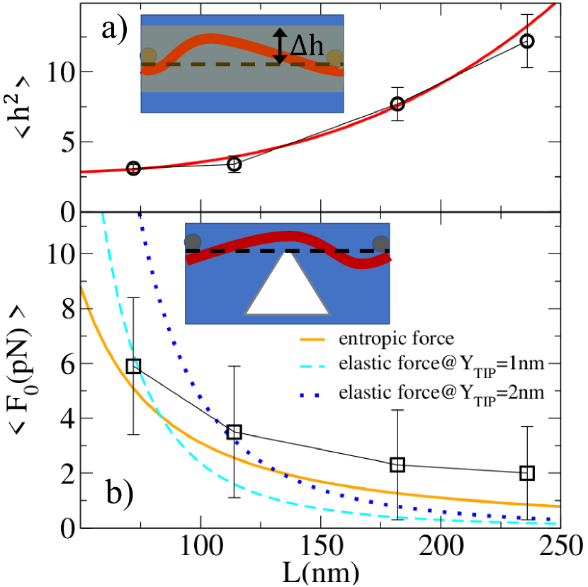
Thus, the membrane mean squared height scales as with the length of the membrane, in good agreement with the result of our MD simulations, as shown Fig.4a. Analogously, one can estimate the radius of curvature of an undulation mode of amplitude , namely:SI
| (3) |
Next, following Daniels and Turner Daniels and Turner (2004), we calculate the partition function of a membrane whose mid-point is constrained to fluctuate only above a certain height, i.e. , representing the position of the tip of an infinitesimally sharp indenter. This is given by:
| (4) |
The path integral over the configuration of the height field is readily calculated using standard algebraic manipulations. This yield, up to a constant prefactors, , where is the complementary error function. Differentiating the free energy with respect to and expanding for around finally yields an expression for the force experienced by the membrane in proximity of the tip, namely:
| (5) |
Some comments are in order. Eq. (5) consists of two terms representing the elastic and entropic contributions respectively. At , the second term vanishes and the force matches the Euler-Bernoulli loading force in a three-point bending configuration (see SI and Ref. Timoshenko and Gere (2012)). More importantly, Eq. (5) demonstrates that upon increasing , the force crosses over from elastic (small ) to entropic (large ).
To highlight the role of the entropic contribution, we have used MD simulations to calculate the force experienced by the indenter at , when the elastic contribution becomes negligible. This is shown in Fig. 4b as a function of the membrane size (square dots), together with the analytical estimate given in Eq. (5) (solid line). By constrast, the dashed and dotted lines show the elastic contribution to the force given in Eq. (5) at the same temperature, but for nm and nm respectively. As is reduced, the elastic contribution overweights the entropic one even at small deformations.
Combining these findings with the results of our MD simulations, we conclude that the rupture of a lipid membrane indented by a microscopic tip results from two different forces: a standard Hookean force, originating from a direct contact between the tip and the membrane and linearly proportional to the indentation depth, and an entropic force, determined the hindrance of the thermal ondulation caused by the presence of the tip. Depending on the size of the membrane, hence the magnitude of the height fluctuation , and the indentation depth , rupture can occur as a consequence of the elastic force, for , or as a consequence of the entropic force, for . In this latter case, the radius of curvature of the membrane does not depend on the sharpness of the indenting tip, but is determined by the temperature, , bending stiffness, and mean amplitude of fluctuation, , as shown in Eq.(3).
Furthermore, we stress that, at constant indentation velocity, large membranes are more prone to entropic rupture and lower rupture forces. In fact, as shown in Eq. (5), the loading rate (i.e. the rate with which the force grows) decreases as the membrane size increases. Considering that the rupture force of biomembranes grows logarithmically with the loading rate Evans et al. (2003), we expect a decrease of the rupture force in the entropic regime where the loading rate is low. This is in agreement with the simulation results of our computer model, showing indeed loading rate-dependent rupture forces SI .
Our findings have a potential immediate application to tissue engineering and drug delivery, where, in order to achieve a fast and effective access to the cell’s interior, nanometer-sized needles are often employed Shalek et al. (2010); Gopal et al. (2019). Our analysis suggests that these techniques can be optimized by suppressing the thermal undulations, as in the case of cells cultured on sharp nanopillars. In this set-up, the cell tightly wraps around the pillar Berthing et al. (2012); Zhao et al. (2017), which then determine the shape of the plasma membrane, thus hindering thermal fluctuations. Conversely, when cells are cultured on a substrate, the free surface in contact with the culture medium is mobile and subject to thermal fluctuations Evans et al. (2008). Such a mobile, undulating interface could be insensitive to the geometry and sharpness of an approaching AFM tip, thus rendering standard perforation strategies uneffective.
References
- Alberts et al. (2002) B. Alberts, A. Johnson, J. Lewis, and M. Raff, Molecular Biology of the Cell (Garland Science, 2002).
- Gennis (1989) R. B. Gennis, Biomembranes (Springer New York, 1989).
- Dipalo et al. (2018) M. Dipalo, G. Melle, L. Lovato, A. Jacassi, F. Santoro, V. Caprettini, A. Schirato, A. Alabastri, D. Garoli, G. Bruno, et al., Nature Nanotechnology 13, 965 (2018).
- Tian and Lieber (2019) B. Tian and C. M. Lieber, Chemical Reviews 119, 9136 (2019).
- Ma et al. (2012) Y. Ma, R. J. M. Nolte, and J. J. L. M. Cornelissen, Adv. Drug Deliv. Rev. 64, 811 (2012).
- Xie et al. (2012) C. Xie, Z. Lin, L. Hanson, Y. Cui, and B. Cui, Acta Crystallographica Section B 7, 185 (2012).
- Chen et al. (2019) Y. Chen, S. Aslanoglou, G. Gervinskas, H. Abdelmaksoud, N. H. Voelcker, and R. Elnathan, Small p. 1904819 (2019).
- Xie et al. (2013) X. Xie, A. M. Xu, M. R. Angle, N. Tayebi, P. Verma, and N. A. Melosh, Nano Lett. 13, 6002 (2013).
- Xie et al. (2015) X. Xie, A. Alipour, S. V. Gupta, and N. A. Melosh, ACS Nano 9, 11667 (2015).
- Angle et al. (2014) M. R. Angle, A. Wang, A. Thomas, A. T. Schaefer, and N. A. Melosh, Biophysical Journal 107, 2091 (2014).
- Obataya et al. (2005) I. Obataya, C. Nakamura, S. Han, N. Nakamura, and J. Miyake, Biosensors and Bioelectronics 20, 1652 (2005).
- Venturoli et al. (2006) M. Venturoli, M. M. Sperotto, M. Kranenburg, and B. Smit, Physics Reports 437, 1 (2006).
- Ayton et al. (2006) G. S. Ayton, J. L. McWhirter, and G. A. Voth, J. Chem. Phys. 124, 064906 (2006).
- (14) See supplementary information at http://… (????).
- Capozza et al. (2018) R. Capozza, V. Caprettini, C. A. Gonano, A. Bosca, F. Moia, F. Santoro, and F. D. Angelis, ACS Applied Materials & Interfaces 2018 10 (34), 29107-29114 10, 29107 (2018).
- Steltenkamp et al. (2006) S. Steltenkamp, M. M. Müller, M. Deserno, C. Hennesthal, C. Steinem, and A. Janshoff, Biophys J. 91, 217 (2006).
- Mey et al. (2009) I. Mey, M. Stephan, E. K. Schmitt, M. M. Müller, M. B. Amar, C. Steinem, and A. Janshoff, J. Am. Chem. Soc. 131, 7031 (2009).
- Alessandrini and Facci (2012) A. Alessandrini and P. Facci, Micron 43, 1212 (2012).
- Helfrich (1978) W. Helfrich, Z. Naturforsch. 33a, 305 (1978).
- Abillon and Perez (1990) O. Abillon and E. Perez, Phys. France 51, 2543 (1990).
- Israelachvili (2011) J. N. Israelachvili, Intermolecular and Surface Forces (London: Academic Press, 2011).
- Lindahl and Edholm (2000) E. Lindahl and O. Edholm, Biophysical Journal 79, 426 (2000).
- Daniels and Turner (2004) D. R. Daniels and M. S. Turner, J. Chem. Phys. 121, 7401 (2004).
- Timoshenko and Gere (2012) S. Timoshenko and J. Gere, Theory of Elastic Stability, Dover Civil and Mechanical Engineering (Dover Publications, 2012), ISBN 9780486134802.
- Evans et al. (2003) E. Evans, V. Heinrich, F. Ludwig, and W. Rawicz, Biophys. J. 85, 2342 (2003).
- Shalek et al. (2010) A. K. Shalek, J. T. Robinson, E. S. Karp, J. S. Lee, D.-R. Ahn, M.-H. Yoon, A. Sutton, M. Jorgolli, R. S. Gertner, T. S. Gujral, et al., Proceedings of the National Academy of Sciences 107, 1870 (2010).
- Gopal et al. (2019) S. Gopal, C. Chiappini, J. Penders, V. Leonardo, H. Seong, S. Rothery, Y. Korchev, A. Shevchuk, and M. M. Stevens, Advanced Materials 31, 1806788 (2019).
- Berthing et al. (2012) T. Berthing, S. Bonde, K. R. Rostgaard, M. H. Madsen, C. B. Sørensen, J. Nygård, and K. L. Martinez, Nanotechnology 23, 415102 (2012).
- Zhao et al. (2017) W. Zhao, L. Hanson, H.-Y. Lou, M. Akamatsu, P. V. Chowdary, F. Santoro, J. R. Marks, A. Grassart, D. G. Drubin, Y. Cui, et al., Nature Nanotechnology 12, 750 (2017).
- Evans et al. (2008) J. Evans, W. Gratzer, N. Mohandas, K. Parker, and J. Sleep, Biophysical Journal 94, 4134 (2008).