Annihilation of Point Defect Pairs in Freely Suspended Liquid-Crystal Films
Abstract
We study the annihilation of topological defect pairs in the quasi-twodimensional (2D) geometry of freely suspended smectic films. This elementary process is at the basis of all models describing the statistics of complex defect patterns. We prepare pairs with opposite topological charges and retrieve the interaction mechanisms from their trajectories. The square-root dependence of the defect separation on the time until annihilation and the asymmetry in propagation velocities of the opponents predicted by theory are confirmed. The importance of defect orientations is demonstrated. Trajectories are in general curved, depending on the mutual orientations (phase mismatch) of the defects and on the orientation of the pair respective to the far, undisturbed director. The experiments provide the basis for an adaption of the theoretical models to the real complexity of the annihilation.
Topological defects occur in a wide variety of physical systems, for example in soft matter Poulin et al. (1997); Poulin and Weitz (1998); Muševič et al. (2006); Brugués et al. (2008); Tkaleč et al. (2011); Guimaraes et al. (2013); Muševič (2019), quantum systems Onsager (1949); Weiler et al. (2008); Polkovnikov et al. (2011), thin magnetic films Wachowiak et al. (2002); Hertel and Schneider (2006), superfluid liquids Ruutu et al. (1996); Bäuerle et al. (1996, 1996), and even cosmology Volovik and Mineev (1977); Chuang et al. (1991). Often, complex defect patterns are generated after symmetry-breaking phase transitions. Their coarsening dynamics can be essential for the establishment of the new, ordered state.
Many features of defect dynamics are universal. Liquid crystals (LCs) were suggested as ideal model systems to study such phenomena Chuang et al. (1991); Bowick et al. (1994); Zurek (1996); Kibble and Srivastava (2013). Their defect dynamics can be observed in facile polarizing microscopy experiments, with comparably simple equipment. The elementary process of pair annihilations of topologically opposite-charged point defects allows to construct scaling solutions for more complex defect patterns.
Nematics form the simplest LC mesophase, yet experiments with nematics in sandwich cells are not easy to interpret, because of the influence of cell boundaries and the generally 3D character of the deformations. Smectic C (SmC) freely suspended films Young et al. (1978) are the quasi-2D analogue of a polar nematic, ideally suited to study topological defect dynamics Pleiner (1988); Svenšek and Žumer (2003, 2003); Radzihovsky (2015); Muzny (1994); Wachs (2014); Stannarius and Harth (2016). Here, we explore the role of defect orientations in pairs with opposite topological charges during annihilation.
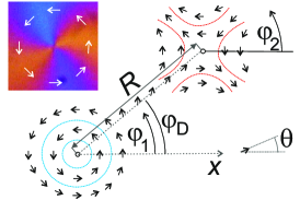
In SmC, the mesogens have a preferred tilt to the smectic layer normal. The c-director (projection of the tilt direction onto the film plane) characterizes the local orientation. Its dynamics is well described by continuum models. The 2D character of the problem simplifies modeling and reduces boundary effects to the far-away film edges. Optical textures reflect the local c-director orientations, the types and positions of defects. Yet even though such experiments are apparently quite simple, there are only few reports on defect dynamics in SmC films Muzny and Clark (1992); Muzny (1994); Pargellis et al. (1994); Wachs (2014); Stannarius and Harth (2016), none about pair annihilation. The polar c-director can only form defects of integer strengths. It shares this feature with all other systems where vortices of vector fields are relevant (e. g. Wachowiak et al. (2002); Hertel and Schneider (2006)). A scenario of primary interest is the annihilation of pairs with topological charges (We may set without loss of generality). The angle of the c-director with the axis at positions near the defect cores , is , where are the phases of the defects and are the angles of the relative positions with the axis (see Fig. 1).
Models for defect interactions were developed for nematics in one-constant elastic theory Dafermos (1970); Minoura et al. (1997); Kleman and Lavrentovich (2003), and extended to SmC films Pleiner (1988); Svenšek and Žumer (2003, 2003); Radzihovsky (2015), where elastic anisotropy Svenšek and Žumer (2003, 2003) and dynamic influences Radzihovsky (2015) were included. The simplest model is derived from linear superposition of single-defect equilibrium solutions of the director field Dafermos (1970). It assumes that the defects pass quasi-equilibrium states. The force between them, acting along the separation vector , is Chandrasekhar and Ranganath (1986); Kleman and Lavrentovich (2003). is a mean elastic constant, . The drag forces on the defects are approximately proportional to Chandrasekhar and Ranganath (1986), thus one obtains a time dependence where is the annihilation time, is a diffusion coefficient that contains , the rotational viscosity , and the Ericksen number Chandrasekhar and Ranganath (1986). The defects approach each other on straight paths. Because of an asymmetric coupling to backflow, the defect is predicted to move considerably faster than the opponent Svenšek and Žumer (2003). The pair does not annihilate halfway, but closer to the initial position.
All these models implicitly assume that the defect orientations match, i. e. that the c-director is constant along the straight connection between the defect cores. Vromans and Giomi Vromans and Giomi (2016) noticed that the so far disregarded mutual orientations are essential features. Tang and Selinger Tang and Selinger (2017), generalized this idea to arbitrary defect strengths. For conjugated pairs with and , their equations read
The generalized equations for conjugated defect pairs with charges are found in Appendix A. Note that the terms and in the definitions of and arise from the correct choice of the quadrants of the arctan functions used in Ref. Tang and Selinger (2017). While these equilibrium distortions are exact, they do not preserve the c-director far from the defects, In experiments, one usually studies defect dynamics under fixed boundary conditions, thus one needs to rotate these solutions to fix . We choose (primed angles in the rotated system) without loss of generality. In the primed system rotated by , the equilibrium solutions are given by
| (2) |
The mismatch remains unchanged, , and the phase of the defect is preserved. Note that and are not independent of each other in equilibrium. After a coordinate transformation that fixes , it becomes clear that the defect always chooses an equilibrium mismatch angle in accordance with its position and vice versa in a given external c-director field, corresponding to the energetic minimum. This aspect was not noticed in Ref. Tang and Selinger (2017) where director field in infinity was disregarded.
These models presuppose elastic isotropy, i. e. equal elastic constants for c-director splay, , and bend, . This may be used as a reasonable first approximation for our experiments (where ), except in the very vicinity of the defect. When is lower than , which is the predominant situation, all defects adopt tangential orientation () in equilibrium. Such a pinning of the alignment angle at a vortex is typical for other systems, too, e. g. in magnetic thin films. The deformation near the core is pure bend, and the c-director is pinned near the core. Even small differences suffice to fix the phase. This was demonstrated in previous experiments Stannarius and Harth (2016) which revealed some limitations of the classical models in SmC films.
This pinning is the only specific aspect that we need to add in the description of our system: we set . For , all conclusions will be the same except that one has to change the sign of the c-director. The defects are less affected by elastic anisotropy, their director field is only slightly modified, and the phase only rotates the defect. During the annihilation process, a mismatched pair () either has to move to an appropriate angle , or the defect has to rotate (change ), or both.
In our experiments, we demonstrate the interrelation of the two important orientation parameters, the phase mismatch of the pair and the misalignment relative to the far c-director. The definition of is chosen such that it reaches zero when the defect orientations match, . This is a reasonable choice, as is exactly the c-director angle near the core on the side opposing the conjugate defect. The pair is considered aligned when this angle equals , i. e. when the defect is opposing the direction where near the defect.
We performed experiments with a room temperature smectic C mixture of 50:50 wt.% 5-n-octyl-2-[4-(n-hexyloxy)phenyl]-pyrimidine and 5-n-decyl-2-[4-(n-octyloxy) phenyl]-pyrimidine. Defects were created by touching the homogeneously oriented free-standing film with a hair tip. In 24 experiments, we obtained isolated defect pairs. Initial separations were of the order of 200 m. The initial alignment angle could not be controlled, it was determined a posteriori from the video images. The defect pairs were observed in a microscope under crossed polarizers with a diagonal wave plate (550 nm, slow axis from top right to bottom left). Video frame rates were 30 fps, in a few experiments 50 fps. The defect positions are easily localized in the images, with an accuracy of approximately 1 m. The c-director orientations are retrieved from texture colors, the accuracy is . The relation between c-director and optical texture is indicated in Fig. 1. We cannot determine the sign of with our observation technique, thus we choose a given sense of direction and use this assignment consistently for all experiments. This has no consequences for the evaluation of data, the equations are independent of the sign of the tilt azimuth. It is possible that all arrows in the images actually represent .
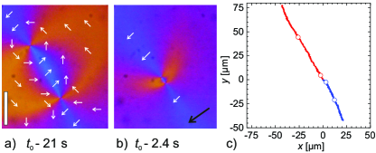
Figure 2 shows an initially matching () and aligned () defect pair. Such conditions (within approximately 10∘ accuracy) were achieved coincidentally in 5 experiments. Eq. (2) predicts that when the orientations match, the misalignment with the director will be . This agrees with our observations. Immediately before annihilation, we found and in all experiments except one. When this relation is coincidentally fulfilled already after preparation, then and remain constant and the defects follow straight paths. The defect is much faster than the , in qualitative agreement with theory Toth et al. (2002); Svenšek and Žumer (2003).
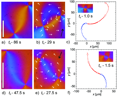
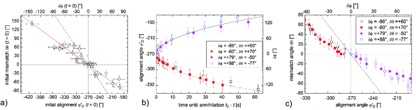
The other 19 experiments randomly produced defect pairs with either positive or negative misalignment . Figure 3(a-c) shows a typical example with initially negative and positive . The c-director changes along the defect connection line, and the texture adopts an S-shape. The trajectory is no more straight, it has mirrored-S-shape. The defect is still faster than the defect. This trajectory of Fig. 3(c) is typical for all similar initial conditions. The angle changes during the approach, finally reaching . Immediately before annihilation the defects are both orientation matched, , and aligned, . This holds for all defect pairs independent of the initial angles. The case of initially negative and positive produces the opposite curvature, as shown in Fig. 3(d-f). The texture forms a mirrored S between the defects, the trajectory has S-shape. For all defect pairs, the misalignment follows a square-root dependence on the time to annihilation (Fig. 4a).
For the test of the predictions of Ref. Tang and Selinger (2017), it would be informative to observe other initial combinations of and , e. g., both with the same sign. In fact, this was never achieved in our experiment. All initial combinations are plotted in Fig. 4b). There is an obvious correlation, irrespective of the deviations that are most probably caused by global distortions of the film orientation when the defects are created. Equation (2) suggests a relation in the quasi-equilibrium states (elastic energy minima at fixed defect positions), which is in clear contrast to the experiment.
The preparation technique produces random alignment angles , but it seems unlikely that touching the films creates correlated combinations of and (even though this cannot be strictly excluded). We cannot see the first few seconds after defect formation for technical reasons, but we conclude that the defects rearrange within this short period after creation, irrespective of the initial conditions, into an orientation that fulfills the condition , at least approximately. It is reasonable to assume that the rotation of the defect in place can proceed much faster than a spatial displacement of the same defect on a circle around the opponent. The reason why there is a factor of nearly 2 between the calculated equilibrium states Tang and Selinger (2017) and the experimental observation at least for large is not clear. A dynamic solution of the differential equations for the c-director might elucidate this.
We conclude that (1) the system establishes certain combinations of and spontaneously, irrespective of the details of the defect creation, and (2) either the experimental system does not develop through quasi-equilibrium states on the way to annihilation, or the equilibrium states are different from those predicted from one-constant elastic theory. A qualitative estimation of the effects of elastic anisotropy on the equilibrium alignment is given in Appendix B.
The ‘initial’ angles in Figs. 3 and 4a are in a way arbitrary, they were taken after the defect preparation as soon as the microscope was focussed onto the film surface in the spot where the defects appeared. This takes a few seconds, differing between individual runs. Initial fast reorientations of the c-director field are not accessible. After these transients, the relations between misalignment and mismatch obviously remain fixed until annihilation, where both and reach zero. As a test of this invariance, Fig. 4c) shows four typical experiments, two with S-shaped and two with mirrored S-shaped trajectories. The two angles and remain strongly correlated, roughly proportional to each other, although there is a slight tendency of to relax faster than . Again, quasi-equilibrium configurations would correspond to . This is the consequence of the fixed , a property that our system shares, e. g., with thin permalloy films Wachowiak et al. (2002); Hertel and Schneider (2006).
With respect to the model Tang and Selinger (2017), our hypothesis is that the equilibrium configurations for are not appropriate quantitative descriptions of the states the annihilating defect pair passes on its approach. The torque predicted from the quasi-equilibrium configurations in Ref. Tang and Selinger (2017) is probably causing an initial reorientation of the defect, which is too fast to be observed in our experiment. The relation observed in our study is presumably a balance between the torque exerted by the opponent and the torque exerted by the far c-director field. The latter is obviously not modeled in Tang’s study Tang and Selinger (2017) in a way appropriate to describe our experiment with fixed boundary conditions.
The relaxation on curved trajectories, which at first glance looks very similar to the numerical simulations in Refs. Vromans and Giomi (2016); Tang and Selinger (2017), appears to be primarily caused by the torque of the external director on the topological dipole. One can consider this as an analogue, with some peculiarities, of an electrical dipole in a uniform external field. The electrical dipole tends to align parallel to the external field to minimize its energy. Likewise, the conjugated topological defect pair can optimize its elastic energy, no matter what the mismatch angle is, by choosing a proper orientation respective to the uniform far c-director . If one defines the ‘topological dipole’, for instance, as a unit vector pointing from the to the defect, the energetic minimum is defined by the angles in Eq. (2). In our experiments, where , the topological dipole aims to align with an angle respective to . We note that the situation of a fixed is quite common, not only for smectic films, in particular in systems where the divergence of the vector field is suppressed or inhibited (vortex flow of an incompressible liquid or splay of a magnetic or electric polarization). In the general case of arbitrary integer or half-integer charges , one finds equilibrium orientations of the topological dipole defined by the vector from the to the core
| (3) |
(see Appendix A). The relaxation of follows a similar square-root time dependence as the defect separation . This produces the observed curved trajectories as seen in Fig. 2. In half-integer pairs, both defects can rotate and the situation is more complex (see Appendix A), but the combination of the two torques of the conjugate defect and the far field, respectively, remains effective.
We have demonstrated that the shape of trajectories of mutually annihilating topological defect pairs is equally influenced by their relative orientations (mismatch) and the surrounding vector field (misalignment), both being of equal importance. They are not independent of each other. We suspect that this is a common feature of topological defect pairs in many other 2D systems. During approach, misalignment and mismatch decay to zero, depending on the time until annihilation by a square-root law. The classical theories Dafermos (1970); Minoura et al. (1997); Kleman and Lavrentovich (2003); Svenšek and Žumer (2003) remain valid for the special case of aligned, matching pairs. The c-director configurations during the approach are qualitatively similar to quasi-equilibrium states determined from the solutions of the Laplace equation Tang and Selinger (2017), but differ quantitatively. This may be caused in our films by flow-coupling Svenšek and Žumer (2003), elastic anisotropy Svenšek and Žumer (2003); Brugués et al. (2008), or the finite film area. An explanation of this discrepancy requires further studies.
Appendix A: Director fields around conjugated point defects
We consider a vector field (c-director) or director field (n-director) which is characterized by a unit vector that is oriented at an angle respective to the axis in a two-dimensional plane . Further, we assume that the equilibrium configurations are defined by solutions of the Laplace equation. For the liquid crystal systems considered here, this means that we assume that the elastic constants for bend, , and splay, , are equal.
For general pairs of conjugated defects with and , the equations given by Tang and Selinger Tang and Selinger (2017) for the solutions of the Laplace equation read
| (4) |
The terms and in the definitions of and arise from the correct explicit choice of the quadrants of the arctan functions used in Ref. Tang and Selinger (2017). The angle defines the orientation of the connection vector from the core of the defect to the core of the defect respective to the coordinate axis . The c-director field far from the two defects approaches the uniform value , i. e.
| (5) |
which depends upon the phases of the two defects, which are in general not constant during their mutual approach and annihilation. In experiments, the far director field is usually fixed, and independent of the defect configurations. Therefore, it is useful for an interpretation of the equilibrium configurations to consider them with respect to the far c-director orientation. We rotate the coordinate system such that the infinitely far c-director is along , i. e. . Thus, the new equations for the c-director field near the two defect cores are transformed to . With the transformations , , the new phase angles are
| (6) |
and
| (7) |
In the special case of the lowest topological strength of a polar vector field, one obtains
| (8) |
whereas for the lowest strength half-integer defects of nonpolar (nematic) orientation fields, , one finds
| (9) |
One can easily recognize that gives the correct boundary condition in all cases.
The phase mismatch remains invariant under transformations of the coordinates because it is defined by the reorientation of the c-director along the straight line connecting the two defect cores. The defect misalignment angle changes to
| (10) |
We replace by the misalignment angle and obtain
| (11) |
In terms of the primed quantities (angles respective to the infinite c-director), using Eqs. (6,7), one obtains
| (12) |
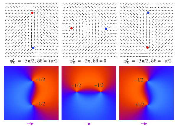
These solutions are visualized in Figs. 5,6. The c-director or director fields, resp., are shown for three situations in each figure. In the middle, the mutually matching, aligned pairs are shown. In both figures, we have arbitrarily chosen . In the case, this corresponds to our experimental situation. In general, other orientations may be conceived as well. In particular, in (strongly polar) smectic C films with , one could have the situation or . In the general (nematic) case, there exist solutions for arbitrary angles that are equivalent. This is shown exemplarily in Fig. 7.
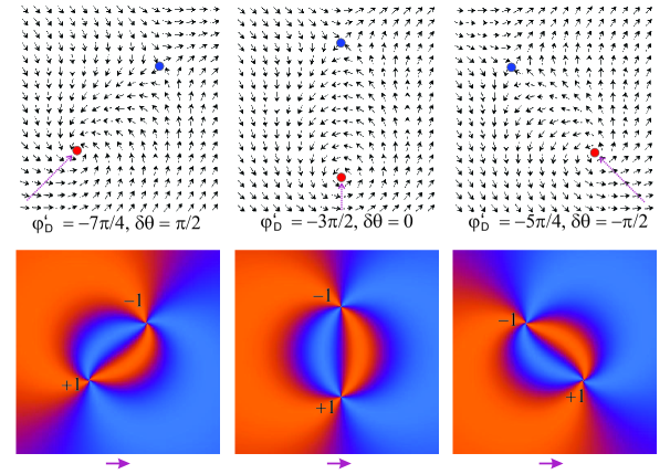
In the special case of , the geometrical interpretation of the misalignment is immediately evident: is the angle of the c-director near the core of the positively charged defect at the side opposite to the conjugate defect (head of dotted arrows in Fig. 5). This means, when two aligned and mutually matching defects annihilate, they leave a non-distorted c-director field behind. If , then the c-director on the connecting axis at both sides of the pair differs from the boundary condition , this is denoted by the term ”misalignment” () of the pair. After a hypothetical annihilation of such a pair, the c-director field would be defect-free but distorted at the annihilation site, it would have to rotate locally to become uniform. Thus, it is justified to describe the misalignment by the angle . In equilibrium configurations defined by Eq. (Appendix A: Director fields around conjugated point defects), for fixed defect positions, this misalignment is linearly related to the mismatch. In the experiments with the free-standing smectic films, a similar linear relation is found, although with a different factor.
This situation is specific for the pair. In all other cases, the situation is more complex and a simple geometrical interpretation of misalignment is not immediately evident. This is demonstrated in Fig. 7. The figure shows three examples of defect pairs that match each other (). The relation given in Eq. (12) is fulfilled in all three situations, and the defects can annihilate each other approaching on a straight path, leaving an undistorted director with orientation behind. Note that this orientation is (and remains) equal to that of the director on the connecting line, at the sides opposing the partner defect, as indicated by dotted lines in the figure. For the general definition of misalignment of defect pairs, one may introduce in analogy to the case from Eq. (12) by
| (13) |
Then, the defect pairs in Fig. 6 would have and the defect pairs would have . The theoretical relation between misalignment and mismatch angles in one-constant approximation would be .
Appendix B: Beyond one-constant approximation: Distribution of splay and bend contributions

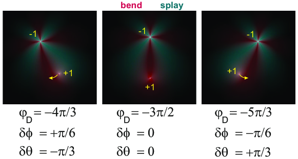
We will analyze here whether the deviation of the measured from the theory can be attributed to the elastic anisotropy present in the experiment, but neglected in the analytical model? The splay and bend contributions to the elastic deformations of the c-director are not uniformly distributed around the defect pair. This is irrelevant in one-constant approximation where both contributions are related to an average elastic constant . In case of , the equilibrium configurations are no longer computable from solutions of the Laplace equation. Analytical solutions are only available for very special geometries. In the present problem of the defect pair, the non-linear differential equation describing the equilibrium has to be solved numerically. The numerical calculation of the exact energies of the equilibrium solutions in that case is not straightforward because the energy density becomes very large near the defect cores. We can, however, estimate the influence of an elastic energy by considering the distribution of splay and bend in the c-director field. Figure 8 shows three situations where a defect pair is aligned (center) and misaligned by a positive or negative (left and right, resp.). The logarithm of the local elastic energy densities of the splay (green) and bend (purple) terms were calculated and color-coded.
In the situation present in our experiment, , the system will tend to compress bent regions in favor of expanding splay regions (compared to the one-constant solutions). One may expect that in Fig. 8, the bent c-director region (purple) below the defect will contract, the splayed (green) regions at both sides of this region will expand. In a simplistic interpretation, this means that in the left image, where is positive, the defect will be relocated clockwise around the defect, reducing and . In the right image, the defect relocates counterclockwise, thus increasing . This effect is opposite to the observation in the experiment where we find much larger than the value predicted in the one-constant model.
One may conclude from these considerations that the elastic anisotropy has an influence on the relation between misalignment and mismatch. However, it seems that it is not the primary cause of the observed differences between experiment and model Eq. (Appendix A: Director fields around conjugated point defects) since the elastic anisotropy effects apparently increase the discrepancy. An accurate computation of the actual equilibrium configurations at will be needed to verify this relation quantitatively.
Acknowledgments
The German science foundation DFG is acknowledged for support within project STA 425/42-1, HA 8467/2 and HA 8467/3. The German Space Administration DLR is acknowledged for support within grant 50WM1744. P. S. was supported by a DAAD/MÖB mobility grant. We thank J. Selinger and X. Tang very much for stimulating discussions.
References
- Poulin et al. (1997) P. Poulin, H. Stark, T. C. Lubensky and D. Weitz, Science, 1997, 275, 1770–1773.
- Poulin and Weitz (1998) P. Poulin and D. Weitz, Phys. Rev. E, 1998, 57, 626–637.
- Muševič et al. (2006) I. Muševič, M. Skarabot, U. Tkaleč, M. Ravnik and S. Žumer, Science, 2006, 313, 954–958.
- Brugués et al. (2008) J. Brugués, J. Ignés-Mullol, J. Casademunt and F. Sagués, Phys. Rev. Lett., 2008, 100, 037801.
- Tkaleč et al. (2011) U. Tkaleč, M. Ravnik, S. Čopar, S. Žumer and I. Muševič, Science, 2011, 333, 62–65.
- Guimaraes et al. (2013) R. R. Guimaraes, R. S. Mendes, P. R. G. Fernandes and H. Mukai, J. Phys.: Cond. Mat., 2013, 25, 404203.
- Muševič (2019) I. Muševič, Eur. Phys. J.-ST, 2019, 227, 2455–2485.
- Onsager (1949) L. Onsager, Il Nuovo Cimento, 1949, 6 (Suppl. 2), 279–287.
- Weiler et al. (2008) C. N. Weiler, T. W. Neely, D. R. Scherer, A. S. Bradley, M. J. Davis and B. P. Anderson, Nature, 2008, 455, 948–951.
- Polkovnikov et al. (2011) A. Polkovnikov, K. Sengupta, A. Silva and M. Vengalattore, Rev. Mod. Phys., 2011, 83, 863.
- Wachowiak et al. (2002) A. Wachowiak, J. Wiebe, M. Bode, O. Pietzsch, M. Morgenstern and R. Wiesendanger, Science, 2002, 298, 577.
- Hertel and Schneider (2006) R. Hertel and C. M. Schneider, Phys. Rev. Lett., 2006, 97, 177202.
- Ruutu et al. (1996) V. M. H. Ruutu, V. B. Eltsov, A. J. Gill, T. W. B. Kibble, M. Krusius, Y. G. Makhlin, B. Placais, G. E. Volovik and W. Xu, Nature, 1996, 382, 334.
- Bäuerle et al. (1996) C. Bäuerle, Y. M. Bunkov, S. Fisher, H. Godfrin and G. R. Picket, Nature, 1996, 382, 332.
- Bäuerle et al. (1996) C. Bäuerle, Y. M. Bunkov, S. N. Fisher, H. Godfrin and G. R. Pickett, Nature, 1996, 383, 570.
- Volovik and Mineev (1977) G. E. Volovik and V. P. Mineev, Sov. Phys, 1977, 73, 767–773.
- Chuang et al. (1991) I. Chuang, R. Durrer, N. Turok and B. Yurke, Science, 1991, 251, 1336–1342.
- Bowick et al. (1994) M. J. Bowick, L. Chandar, E. Schiff and A. Srivastava, Science, 1994, 263, 943.
- Zurek (1996) W. H. Zurek, Physics Reports, 1996, 276, 177.
- Kibble and Srivastava (2013) T. Kibble and A. Srivastava, J. Phys.: Condens. Matter, 2013, 25, 400301.
- Young et al. (1978) C. Y. Young, R. Pindak, N. A. Clark and R. B. Meyer, Phys. Rev. Lett., 1978, 40, 773.
- Pleiner (1988) H. Pleiner, Phys. Rev. A, 1988, 37, 3986.
- Svenšek and Žumer (2003) D. Svenšek and S. Žumer, Phys. Rev. Lett., 2003, 90, 155501.
- Svenšek and Žumer (2003) D. Svenšek and S. Žumer, Phys. Rev. Lett., 2003, 90, 219901.
- Radzihovsky (2015) L. Radzihovsky, Phys. Rev. Lett., 2015, 115, 247801.
- Muzny (1994) C. Muzny, M.Sc. thesis, University of Colorado at Boulder, 1994.
- Wachs (2014) K. Wachs, B. A. Thesis, University of Colorado at Boulder, 2014.
- Stannarius and Harth (2016) R. Stannarius and K. Harth, Phys. Rev. Lett, 2016, 117, 157801.
- Muzny and Clark (1992) C. D. Muzny and N. A. Clark, Phys. Rev. Lett., 1992, 68, 804–807.
- Pargellis et al. (1994) A. N. Pargellis, S. Green and B. Yurke, Phys. Rev. E, 1994, 49, 4250.
- Dafermos (1970) C. M. Dafermos, Quart. J. Mech. Appl. Math., 1970, 23, S49.
- Minoura et al. (1997) K. Minoura, Y. Kimura, K. Ito and R. Hayakawa, Mol. Cryst. Liq. Cryst., 1997, 302, 345–355.
- Kleman and Lavrentovich (2003) M. Kleman and O. D. Lavrentovich, Soft Matter Physics: An Introduction, Springer Verlag, 2003.
- Chandrasekhar and Ranganath (1986) S. Chandrasekhar and G. S. Ranganath, Adv. Phys., 1986, 35, 507–596.
- Vromans and Giomi (2016) A. J. Vromans and L. Giomi, Soft Matter, 2016, 12, 6490–6495.
- Tang and Selinger (2017) X. Tang and J. V. Selinger, Soft Matter, 2017, 13, 5481–5490.
- Toth et al. (2002) G. Toth, C. Denniston and J. M. Yeomans, Phys. Rev. Lett, 2002, 88, 105504.