Giant Brillouin amplification in gas using hollow-core waveguides
Abstract
Stimulated Brillouin scattering (SBS) offers among the highest nonlinear gains in solid materials and has demonstrated advanced photonics functionalities in waveguides. The large compressibility of gases suggests that SBS may gain in efficiency with respect to condensed materials. Here, by using a gas-filled hollow-core fibre at high pressure, we achieve a strong Brillouin amplification per unit length, exceeding by 6 times the gain observed in fibres with a solid silica core. This large amplification benefits from a higher molecular density and a lower acoustic attenuation at higher pressure, combined with a tight light confinement. Using this approach, we demonstrate the capability to perform large optical amplifications in hollow-core waveguides. The implementations of a low-threshold gas Brillouin fibre laser and a high-performance distributed temperature sensor, intrinsically free of strain cross-sensitivity, illustrate the large perspectives for hollow-core fibres, paving the way to their integration into lasing, sensing and signal processing.
Stimulated Brillouin scattering (SBS) is a third-order optical nonlinear effect that manifests itself in a coherent light-sound coupling eggleton_brillouin_2019 ; safavi-naeini_controlling_2019 ; wiederhecker_brillouin_2019 ; kobyakov2010stimulated . It is usually the strongest nonlinear effect in amorphous materials eggleton_brillouin_2019 and has been observed in many platforms, such as optical fibres ippen_stimulated_1972 ; dainese_stimulated_2006 ; kang_tightly_2009 , whispering gallery mode resonators grudinin_brillouin_2009 ; tomes_photonic_2009 ; lee_chemically_2012 , integrated waveguides pant_-chip_2011 ; shin_control_2015 ; van_laer_interaction_2015 ; yang_bridging_2018 ; gundavarapu_sub-hertz_2019 and various fluids hagenlocker_stimulated_1965 ; she_stimulated_1983 ; manteghi_spectral_2011 ; mountain_spectral_1966 ; dahan_droplet_2016 ; giorgini_stimulated_2018 .
Gas turns out to be an attractive medium for nonlinear optics because, unlike condensed matter, it is not subject to optical damage at high intensities (with the notable exception of photochemical dissociation for some molecular gases). It shows a pressure-dependent nonlinearity and group-velocity dispersion, as well as a potentially wider transparency window from the vacuum ultraviolet to the mid-infrared region russell_hollow-core_2014 ; travers_ultrafast_2011 . Various nonlinear effects have been demonstrated in gases, including supercontinuum generation corkum_supercontinuum_1986 , high-harmonic generation popmintchev_attosecond_2010 , filamentation berge_ultrashort_2007 , Raman scattering and Brillouin scattering hagenlocker_stimulated_1965 .
So far, backward SBS in gases has been exclusively observed using free space interactions hagenlocker_stimulated_1965 ; she_stimulated_1983 ; manteghi_spectral_2011 . The scattering efficiency remains limited owing to the weak light confinement over a sizeable interaction length, so that high-power laser pulses (megawatt peak power) are needed to eventually observe a moderate SBS signal hagenlocker_stimulated_1965 ; she_stimulated_1983 ; manteghi_spectral_2011 .
Hollow-core fibres (HCFs) including hollow-core photonic bandgap fibres, Kagome-style hollow-core fibres and single-ring antiresonant fibres, show low-loss and diffraction-less optical transmission (state of the art loss: 0.65 dB/km bradley_antiresonant_2019 ). They are therefore the ideal candidate to drastically increase the light-sound interaction length in a gaseous medium and thereby achieve an efficient coupling between interacting waves russell_hollow-core_2014 ; travers_ultrafast_2011 ; dudley_ten_2009 . In free space, a Gaussian beam converging to a spot of diameter results in a nonlinear gain proportional to , where is the effective interaction length. is given by twice the Rayleigh length , where is the laser wavelength in vacuum. As a consequence, the nonlinear gain in bulk gases is proportional to , irrespective of the beam convergence.
On the other hand, in gas-filled HCFs, is solely function of the fibre length and attenuation and can actually reach a few hundred metres. Additionally, the mode field diameter is typically , so that the nonlinear gain in gas-filled HCFs may turn six orders of magnitude larger than in unconfined gases (i.e. in free space) in the near-infrared region. Incidentally, the threshold for nonlinear effects, such as stimulated Raman scattering benabid_stimulated_2002 and Raman frequency comb generation couny_generation_2007 , has been proved to be several orders of magnitude lower than using free-space optics.
It has to be nevertheless mentioned that an opto-acoustic interaction, in this case forward SBS, has been recently demonstrated in HCF filled with air at atmospheric pressure renninger_guided-wave_2016 . In that work, the peak gain coefficient reached , which remains times smaller than the peak backward Brillouin gain coefficient in fibres with a solid silica core (SMF). This gain is clamped down as a consequence of the non-uniformity of the core diameter jarschel_fiber_2018 , since it causes a inhomogeneous gain linewidth broadening. Globally, no strong light-sound interaction in gaseous media has been reported so far.
Here, we report a considerable optical amplification by using backward SBS in a gas-filled HCF. We achieve 0.32 dB of signal amplification per mW of pump power inside a 50 m long HCF filled with carbon dioxide () at a pressure of 41 bar. This large gain results from two causes: firstly, the peak Brillouin gain coefficient shows a quadratic dependence on the gas pressure, in contrast with stimulated Raman scattering russell_hollow-core_2014 and Kerr nonlinearity travers_ultrafast_2011 in which the nonlinear coefficients are typically proportional to the gas pressure. The Brillouin gain can therefore be drastically enhanced in the backward SBS configuration by raising the gas pressure. Secondly, the simultaneous tight confinement of light and gas in a HCF offers altogether an ultra-long interaction length and a small effective beam cross-section.
Using this platform, we demonstrate two original and specific implementations: a low-threshold (33 mW) continuous-wave single-frequency laser in a HCF that can in principle operate at any wavelength, as well as a distributed temperature sensor of unprecedented performance showing zero strain cross-sensitivity, thereby breaking a 30-year physics barrier since Brillouin fibre sensing was first proposed.
Results
Theoretical analysis of the Brillouin gain
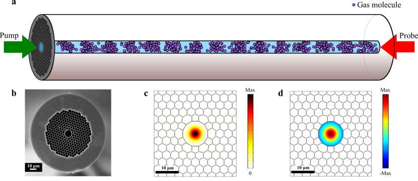
Stimulated Brillouin scattering in a gas-filled HCF is a process in which a pump and probe optical waves with a slightly different frequency counter-propagate along a HCF and their interference produces a longitudinally moving fringe pattern. When a strict phase matching condition is met, dictated by the relative velocities of light and sound in the medium, the fringe pattern gives rise, via electrostriction, to a travelling longitudinal acoustic wave in the gas, as illustrated in Fig. 1(a). In turn, this wave periodically modifies the medium optical density, inducing a Bragg-type coupling between pump and probe. We assume the frequency of the pump light to be higher than that of the probe. In this case, the probe is amplified by the pump when their frequency difference matches the Brillouin frequency shift (i.e. the frequency for perfect phase matching), given by , where is the effective refractive index of the optical mode, is the gas acoustic velocity and is the pump wavelength. Note that Brillouin amplification in gas can be implemented in any hollow-core waveguide, including microstructured fibres, capillary fibres and metal-coated waveguides, as well as slot waveguides. For this first demonstration, we opted for a 50 m long commercial HC-1550-02 HCF from NKT Photonics, since it shows a relatively small optical effective mode area (51 m2), leading to a higher Brillouin coefficient. A scanning electron microscope image of its cross-section is shown in Fig. 1(b). This fibre guides light inside its hollow core by virtue of the photonic bandgap in the periodically patterned cladding region.
During the SBS interaction, the probe wave is amplified with a peak gain given by kobyakov2010stimulated :
| (1) |
where is the electrostrictive constant in the gas medium, is the light angular frequency, is the gas density, is the gas refractive index, is the light velocity in vacuum, is the gain spectrum linewidth (full width at half maximum (FWHM)), directly related to the acoustic attenuation, and is the acousto-optic overlap effective area, as defined and calculated in Supplementary Section S4. Figures 1(c) and (d) show the spatial distributions of the fundamental optical and first excited radial acoustic eigenmodes, respectively (obtained by a finite element method using COMSOL Multiphysics). is calculated from the overlap integral between these 2 distributions. In this work, we consider only the first excited radial acoustic mode, since the Brillouin interaction involving higher acoustic modes is more than 2 orders of magnitude smaller.
The acoustic velocity is given by , independent of pressure for an ideal gas, where is the adiabatic compressibility. As the compressibility coefficient of gases (e.g. at 40 bar) is four orders of magnitude larger than that of solid materials (e.g. fused silica) and the density of gases (at 40 bar) is some 30 times smaller than that of a condensed material, the acoustic velocity is about 20 times smaller. This leads to a 20-fold increase in gain, as shown by Eq. (1), as well as a Brillouin frequency shift lying in the sub-gigahertz range (e.g. MHz for CO2 at a pump wavelength of 1.55 ).
We shall now discuss the two key-parameters contributing to the quadratic dependence of the Brillouin gain on gas pressure: the electrostrictive constant, , and the acoustic attenuation coefficient, .
The electrostrictive constant is defined as the normalised rate of change of the relative permittivity in response to a change in the density boyd_nonlinear_2008 :
| (2) |
where is the electric susceptibility. At the pressure ranges considered in this manuscript, the electric susceptibility of CO2 shows a linear dependence on density: , where for CO2. As a result, the electrostrictive constant:
| (3) |
is directly proportional to the density, hence to the pressure in the ideal gas approximation.
The acoustic attenuation of a sound wave in CO2 at megahertz frequencies arises mainly from two dissipative phenomena: viscous forces and thermal conductivity bhatia1985ultrasonic . Thermal conductivity and viscosity have very similar origins: they arise from energy/momentum diffusion, respectively, driven by thermal motion of the gas molecules which compensates for any temperature/velocity gradient. Hence, their strengths are proportional to the temperature/velocity gradient, respectively. In order to intuitively grasp the pressure dependence in these two processes, let us consider an acoustic plane wave propagating along the -axis in a gas that is globally at rest. Such a wave consists of similar periodic variations of density, pressure, velocity and temperature. In particular, we express the velocity of the gas volume elements as: , where is the velocity amplitude, and are the wave angular frequency and wavenumber, respectively (for backward SBS, ). The intensity of the acoustic plane wave is expressed as:
| (4) |
Within the ideal gas model, it can be shown that the temperature oscillations of the acoustic wave are given by bhatia1985ultrasonic :
| (5) |
where is the average ambient temperature and is the adiabatic index, namely the ratio of specific heats at constant pressure and volume, respectively. Thus, for an intensity kept constant, both gas velocity and temperature periodic variations (and hence, their gradient) decrease for an increasing density . As a consequence, both thermal diffusion and viscosity forces are in proportion equally reduced. It can be more formally shown that the dissipated energy caused by each process is proportional to and the acoustic attenuation coefficient is therefore proportional to , expressed as landau1987fluid :
| (6) |
where and are the shear and bulk viscosity respectively, is the thermal conductivity and is the specific heat at constant pressure. Inserting Eqs. (3) and (6) into Eq. (1), it ends up that the Brillouin gain increases quadratically with the density, thus the pressure in the ideal gas approximation.
SBS gain coefficient measurement
The CO2 Brillouin gain at atmospheric pressure is about m/W. In order to measure such a small gain, a lock-in detection technique has been the preferred approach to separate the gain signal from the background noise and spurious signals. The experimental set-up is detailed in Supplementary Section S1.1. The loss of our HCF filled with 1-bar CO2 is 16 dB/km at our working vacuum wavelength of 1.55 . After gas pressurisation at 41 bar, an additional 0.5 dB loss was measured, caused by the pressure-broadened molecular absorption lines of CO2. All the experiments were performed at an environmental temperature of 24C.
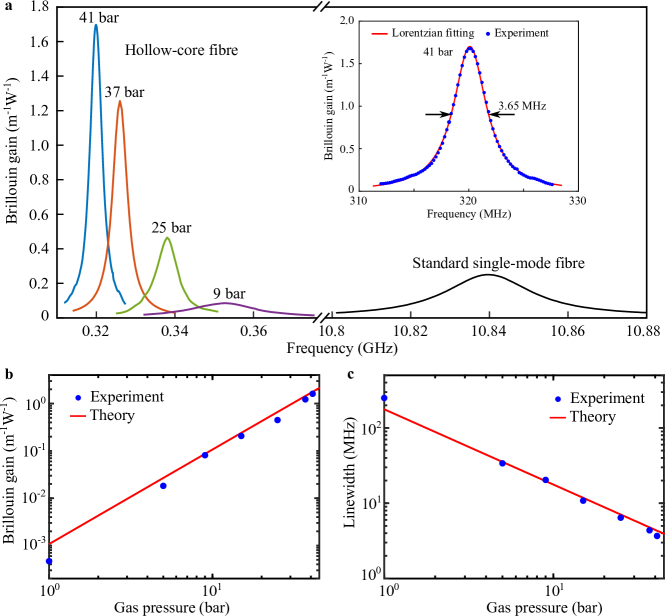
Figure 2(a) shows the measured backward SBS gain spectra of the HCF filled with CO2 at different pressures and, for comparison purpose, of a standard SMF having a solid silica core of very similar diameter. The detailed analysis of the system response is presented in Supplementary Section S1. It can be observed that the Brillouin gain exceeds that of the standard SMF for pressures above bar. Remarkably, when the pressure reaches 41 bar, the measured Brillouin gain coefficient is 1.68 , which turns out to be 6 times higher than in a standard SMF and 20 times higher than the largest Raman gain achievable in gas-filled HCFs at a wavelength of 1.55 (i.e. at pressures above 10 bar, the peak Raman gain from the hydrogen Q(1) transition saturates to 0.08 , see Supplementary Section S5 for a comparative Raman gain analysis). Since the acoustic velocity is of the order of hundreds of meters per second in gaseous media, the Brillouin frequency shift lies in the sub-GHz range, in contrast with the 11 GHz in silica. Note that the acoustic velocity derived from the Brillouin frequency shift shown in Fig. 2(a) decreases with rising pressure (see Supplementary Section S6 for the detailed analysis), caused by a moderate departing from the ideal gas model.
For a 41-bar pressure, the Brillouin linewidth is measured to be 3.65 MHz using a Lorentzian fitting over the experimental spectrum, as shown in Fig. 2(a) inset. This value is 10 times smaller than in a SMF, which means that the acoustic lifetime in the gas is 10 times longer than in a silica core. Figures 2(b) and 2(c) show the Brillouin gain and linewidth measured as a function of pressure. The measured gain coefficients and linewidths match very well with the theoretical model given by Eqs. (1) and (6): the gain is proportional to the square of the pressure, while the linewidth is inversely proportional to the pressure. During this study the maximum gain has been obtained by pressurising CO2 at 41 bar in our 50 m long HCF, so that this configuration has been preferably used in the subsequent experiments.
This HCF propagates several guided optical modes and is therefore not strictly single-moded. The light launching conditions make the fundamental mode to be much preferably populated, so that the conditions are close to a single-mode operation. This is indirectly evidenced by the symmetry and the absence of side peaks in the Brillouin gain spectra. If ever some light propagates in the higher order modes, it would lead to an underestimation of the gain value at worst.
Signal amplification
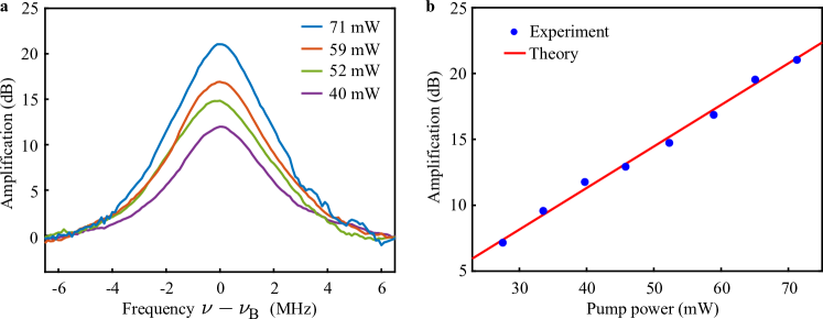
The evident primary application taking advantage of this large gain value is to raise the challenge of optical amplification within a HCF. To this end, we measure the amplification of a 34 dBm input probe beam as a function of pump power. The injected probe power is more than 40 dB smaller than the pump power, hence satisfying the small-signal amplification condition (i.e. absence of pump depletion) at least up to 30 dB amplification. The detailed set-up is shown in Supplementary Section S2.
By scanning the pump-signal detuning frequency, the measured amplification spectra for different pump powers are shown in Fig. 3(a), while the logarithmic peak amplification value in the HCF as a function of the pump power is plotted in Fig. 3(b). The red line in Fig. 3(b) is calculated from the equation: using actual gas and fibre parameters. It shows a slope of 0.32 dB/mW, indicative of the amplification efficiency normalised to the pump power. The experimental results are in perfect agreement with the theoretical prediction. A record 53 dB amplification has been observed for a signal input power below -49 dBm and a pump power of 200 mW inside the HCF (pump-depleted regime).
A straightforward estimation shows that the amplification coefficient could be enhanced up to 1.2 dB/mW by extending the effective length to 160 m using the same 41-bar CO2-filled hollow-core photonic bandgap fibre ( core diameter). This estimation takes into account the 26 dB/km optical loss (16 dB/km of fibre loss and 10 dB/km of molecular absorption loss in 41-bar CO2).
The pros and cons of this Brillouin amplification in gas do not fundamentally differ from those extensively reported in silica-core fibres olsson_characteristics_1987 : very narrow-band efficient amplification that can be spectrally enlarged by broadening the pump spectrum through modulation, at the expense of a lowered efficiency, and poor noise figure that has still to be quantified in the case of amplification in a gas.
Gas Brillouin laser
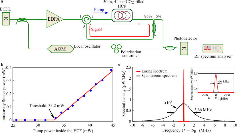
This platform can be straightforwardly turned into a gas Brillouin laser by looping the 50 m long gas-filled HCF, so as to form a fibre ring cavity. Figure 4(a) shows the detailed experimental implementation. The pump light is launched into the cavity through a circulator and, after one revolution, is stopped by that same circulator. Since the pump is not circulating in the cavity, it must not be stringently resonant. In contrast, the Brillouin-amplified light freely circulates in the ring cavity. The total cavity length is 55 m, made of the 50-m HCF connected to 5 m of diverse SMF patchcords (circulator and coupler pigtails), so that the free spectral range of the cavity is 5 MHz, roughly equivalent to the Brillouin gain linewidth of CO2 at 41 bar.
Figure 4(b) shows the Stokes power as a function of the pump power evaluated inside the HCF. Brillouin lasing is turned on when the net Brillouin gain exceeds the round trip loss of the fibre cavity (i.e. 9 dB HCF insertion loss and 2 dB circulator and coupler loss, 11 dB altogether). The measured threshold is 33.2 mW, in good agreement with the theoretically estimated threshold of 34.9 mW. Considering the coupling losses, far from being optimised, this corresponds to a net pump power of 105 mW.
Figure 4(c) shows the heterodyne electrical beating spectra between the frequency-shifted pump laser (as a local oscillator) and the amplified spontaneous Brillouin scattering (50 m long HCF filled with 41-bar CO2, single-pass backscattering through a non-looping cavity) when the pump power inside the HCF is 12 mW, as well as the beat note between the local oscillator and the Brillouin laser emission after closing the cavity, when the pump power inside the HCF is 44.6 mW. The beating spectrum linewidth (FWHM) between the Stokes signal and the local oscillator above threshold is measured to be 66 kHz, which is much narrower than the spontaneous spectrum (3.66 MHz). Since our lasing cavity is neither locked nor isolated from the environment, mode hopping constantly occurs during laser emission. In order to snapshot the heterodyne spectrum during lasing, the resolution bandwidth of the radio-frequency (RF) spectrum analyser is set to 62 kHz to promptly scan a several mega-hertz frequency range. The measured beating linewidth is therefore dominated by this resolution and does not represent the real lasing linewidth, expected to be ultra-narrow.
It should be mentioned that suppression of the mode hopping is possible using reported techniques, for instance by locking the pump-Stokes detuning frequency to a local radio-frequency oscillator danion_mode-hopping_2016 .
Distributed temperature sensing
Temperature/strain cross-sensitivity is currently a crucial issue in all Brillouin-based sensing systems, because the acoustic velocity in a solid is indistinctly sensitive to both these quantities that will identically impact the Brillouin frequency shift. Many methods were proposed to solve this issue by measuring two parameters showing distinct responses to temperature and strain motil_state_2016 . However, no solution, solely based on Brillouin scattering and showing intrinsic strain insensitivity, has been reported so far. The absence of cross-sensitivity is an essential quality of a sensing system.
Raman distributed sensing in silica fibre is known to show no strain cross-sensitivity. However, due to the weak response of spontaneous Raman scattering, the spatial resolution remains limited to bolognini_raman-based_2013 and the distance range to some 30 km hartog_introduction_2018 for a reasonable integration time, far from competing with the performance of a Brillouin-based sensor.
Here, we demonstrate an intrinsically strain-insensitive system based on SBS in gas-filled HCFs. In our system, optical signals keep confined into a gaseous medium, so that this configuration offers unique properties absent in solid waveguides. The absence of plasticity and stiffness of the gaseous medium leads to an insensitivity to any strain applied to its surrounding walls. Here, we take advantage of this specific properties, combined with the large Brillouin gain and its narrow linewidth to perform high performance strain-insensitive temperature measurements.
We used the same 50 m long HCF filled with 41-bar and set up a phase-modulated Brillouin optical correlation-domain analysis system denisov2016going (the detailed set-up is shown in Supplementary Section S3). The Brillouin dynamic grating position is scanned all along the fibre to measure the local Brillouin gain spectrum at each position. A strain applied on the HCF turns out to have a negligible impact on both the gas pressure and the effective optical refractive index and therefore presents no observable effect on the Brillouin frequency shift (see Supplementary Section S7 for the detailed simulation and analysis). In contrast, a change in temperature significantly modifies the acoustic velocity estrada1998speed and hence shifts the Brillouin frequency.
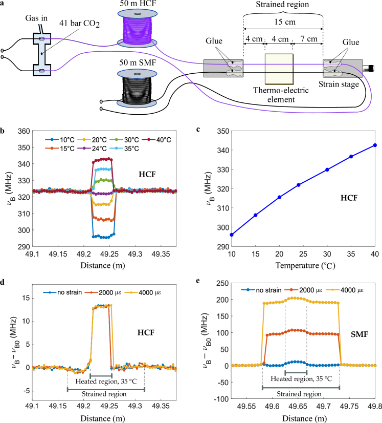
Our sensing system is depicted in Fig. 5(a). For the sake of comparison, identical lengths of HCF and solid-core SMF (ITU G.652) are jointly placed on a test bench consisting of a 4 cm thermo-electric (Peltier) element positioned in the middle of a 15 cm variable strain stage. This enables us to simultaneously apply strain and temperature changes over the same segment and identically for the two fibre types. The small thermo-electric element size turns out to be also decisive to validate the system’s high spatial resolution. For each fibre, the spatial resolution was set to the highest value to secure a signal-to-noise ratio in excess of 10 at the peak gain value. The resulting spatial resolution was 1.28 cm and 2.32 cm for the HCF and SMF, respectively (calculated as the inverse of the bit duration), reflecting the contrasted difference in gain in the two media, despite a higher total loss through the HCF. Measurement spectra were recorded using a 7.8 Hz equivalent noise bandwidth and their peak gain frequency was estimated using a quadratic fitting. The repeatability for the HCF and the SMF is experimentally estimated to be 0.3 ∘C and 0.4 ∘C, respectively (see Supplementary Section S3.7 for additional details).
Figure 5(b) shows the longitudinal distribution of the Brillouin frequency shift for various preset temperatures in the HCF. The slightly different positioning of the step transitions is due to the uncertainty in the central frequency determination when two Brillouin gain spectra overlap in presence of noise. The average Brillouin frequency shift in the HCF along the thermo-electric element as a function of the preset temperature is shown in Fig. 5(c). It should be pointed out that the response is not perfectly linear but shows an average slope of 1.2 MHz/∘C, which turns out to be conveniently slightly larger than for silica. The slope is higher for lower temperatures (in Fig. 5(c)), as a result of the closer vicinity to the liquefaction temperature (C at 41 bar), in agreement with a previous work estrada1998speed .
Figures 5(d) and (e) compare the response of each fibre at a preset temperature of 35∘C and under different applied strains: 0 , 2000 and 4000 . As expected, a strong strain dependence is observed for the SMF, but no change is visible for the HCF, validating the absence of observable cross-sensitivity, which was subsequently confirmed up to 1% elongation. This experimental result consolidates the numerical simulations predicting this strain insensitivity (Supplementary Section S7).
Discussion
The large light-sound interaction in a gas-filled HCF reported here leads to a measured gain nearly six orders of magnitude larger than in previous works using free-space optics. In a pure fibre perspective, the increased compressibility of gases and their lower acoustic attenuation with respect to solid materials result in a measured Brillouin gain in our 41-bar CO2 gas-filled HCF that turns 6 times larger than in standard SMF.
The issue of optical amplification in HCFs has already given rise to sustained efforts. Interesting results have been reported, mostly using molecular/atomic transitions in a low-pressure gas hassan_cavity-based_2016 (as in classical gas lasers) or Raman gain in hydrogen benabid_stimulated_2002 . The obtained gains remain modest in both cases when compared to solid-core solutions, with the specific penalties of amplification at fixed wavelengths for molecular/atomic transitions and the stringent issue of hydrogen permeation through the glass walls for Raman amplification. In contrast, our approach offers an efficient alternative to amplify signals since it shows a gain 20 times larger than the highest achievable Raman gain at 1.55 . Moreover, this amplification scheme operates at any wavelength from the ultraviolet to the mid-infrared region, limited only by the transmission windows of the HCFs.
Gas Brillouin lasing has not yet been reported due to the extremely low scattering efficiency in free-space implementations. Using gas-filled HCF, we have demonstrated the first continuous-wave gas Brillouin laser with only 33 mW of threshold power, despite the high cavity roundtrip loss. The lasing threshold can be further decreased by dynamically matching the cavity resonance to the pump frequency in a doubly resonant configuration (both pump and Stokes are resonant). In addition, by changing the gas pressure, we evidenced that we can not only scale the gain but also modify the acoustic lifetime, which turns out to be a very important feature for building gas Brillouin photon or phonon lasers otterstrom_silicon_2018 . As clarified below, the nature of the gas is not very crucial, so that it can be perfectly possible to realise a gas Brillouin laser using compressed air as amplifying medium.
In a different perspective, we also demonstrated a high-performance distributed temperature sensor showing spatial and temperature resolutions of 1.28 cm and 0.3 ∘C, respectively. Note that, since we used a correlation-domain technique, the 10 times narrower linewidth (i.e. longer acoustic lifetime) compared to silica core SMF has no impact on the spatial resolution, but much improves the temperature resolution soto_modeling_2013 . Our distributed temperature sensor is robustly immune to high energy radiations (e.g. in space-borne situations or inside a nuclear reactor) where conventional solid-glass fibres are rapidly subject to photodarkening bykov_flying_2015 . The sensing range may be potentially extended to several tens of kilometres by using low-loss HCFs bradley_antiresonant_2019 filled with gases free of absorption in the C-band (such as nitrogen or noble gases).
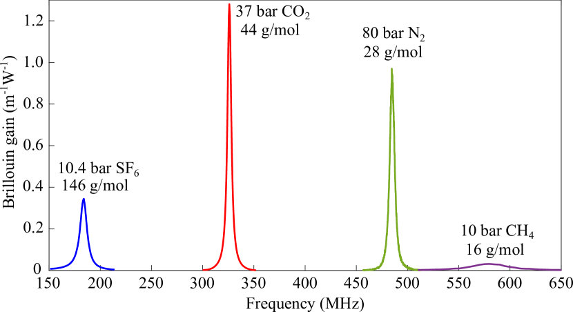
The natural question arises as to how the nature of the gas influences the Brillouin gain. From our theoretical analysis it comes up straightforwardly that the gain depends quadratically on the gas density, so that heavier molecules are expected to present a larger amplification potential. We observed SBS in a HCF filled with different types of gas, namely carbon dioxide (CO2), sulfur hexafluoride (), nitrogen () and methane (). The Brillouin gain spectra for these four gases under specific pressures are plotted in Fig. 6. The acoustic velocity, and hence the Brillouin frequency shift, usually scales inversely to the square root of the gas molecular mass, as demonstrated in Fig. 6. CO2 has been selected in this work for four main reasons: (1) its absorption at a wavelength of 1.55 remains limited below 41 bar, (2) it has a relatively large density, leading to a Brillouin gain 6 times and 3 times larger than and respectively at the same pressure, (3) compared to SF6, CO2 shows a higher liquefaction pressure at room temperature, which results in a higher achievable gain (even though the Brillouin gain of CO2 is 3 times lower than that of at the same pressure (e.g. 10 bar)) and (4) it is widely available, does not permeate through glass and can be handled with no potential hazards.
In our experiments, the maximum pressure used for CO2 is 41 bar, which is not a physical limitation of the HCF, since such fibres can easily sustain a pressure in the kilobar range by virtue of their small core diameter and thick glass sheath russell_hollow-core_2014 . This maximum pressure turns out to lie below the onset of substantial light absorption at 1.55 m. As observed at pressures above 41 bar, the substantial light absorption due to pressure broadening impairs the HCF transmission and hence decreases the Brillouin signal. As a result, it has to be mentioned that the use of complex heavy molecules is eventually of limited relevance, since such molecules normally present broad and numerous absorption bands and frequently liquefy at moderate pressure (e.g. 61 bar for CO2 and 22 bar for ) at room temperature. Using simpler molecules such as nitrogen, oxygen or noble gases opens the possibility to raise the pressure without risk of liquefaction, so that their smaller intrinsic gain can be eventually much overcompensated by a higher pressure. Such gases are normally also totally free of spectral absorption lines in the regions of interest. For instance a theoretical gain up to 30 m-1W-1 is anticipated in a xenon-filled HCF for a pressure above 130 bar. This gain is more than 100 times larger than in a solid-core silica fibre.
Our platform is also suitable for the investigation of light-sound interactions in gases close to their critical point or in the supercritical region, as well as for the study of the bulk viscosity at high frequency, which is, so far, poorly documented. It should be pointed out that the gas consumption in volume for a 50 m long HCF having its core and cladding filled with 1 kilobar gas is equivalent to only about 200 ml at atmospheric pressure, thanks to the microscopic size of the structure. In a more practical approach, the gas-filled HCF can be hermetically sealed by splicing both ends to standard SMFs, thereby making a perfectly airtight compact all-fibre gas cell benabid_compact_2005 which can be flexibly and safely handled.
Stimulated Brillouin scattering cannot be reduced to a mere amplification process, since it has demonstrated its potentialities to realise advanced functions santagiustina_all-optical_2013 . This novel gas-based Brillouin platform can be the foundation of many potential applications, some being partially illustrated here: amplifiers, highly coherent Brillouin gas lasers, slow & fast light, microwave filters, tuneable delay lines, light storage, all-optical calculus and of course sensing. The same functions can therefore be implemented in hollow-core fibres, offering all the inherent assets of fibre-based optics, with the key advantage to realise the same response with a product pump power fibre length potentially 100 smaller. It must be mentioned that the reduced acoustic loss with respect to silica results in a narrower gain resonance: this may be seen at first glance only as a drawback since it reduces the capacity for broadband amplification. However, it turns out to be a clear asset for the majority of applications benefiting from a long-lasting vibration: optical storage, optical signal processing, precisely selective spectral filtering, sensing, etc…
On a broader perspective, the concept introduced in this paper can also be applied to other waveguiding structures. More specifically, although suspended silicon or silica waveguides can be designed to exhibit a light-sound interaction eggleton_brillouin_2019 , the interaction between the evanescent field of their guided light and the gas has not yet been exploited and could lead to gains of practical interest. For instance, a small dimension slot waveguide, inducing an intense evanescent field almeida_guiding_2004 can be designed to offer a large light-sound interaction in gas. This shows that, if the immediate and massive benefit of Brillouin amplification in gas is undoubtedly for hollow core waveguides, its potentialities can certainly extend to other configurations.
Methods
Fabrication of the HCF gas cell
Thanks to the similar core and cladding diameters of our HCF and a standard SMF, the HCF gas cell can be formed by placing a segment of HCF between two SMF patchcords according to the following procedure: (1) two ceramic fibre ferrules having an inner diameter of 125 were inserted into a ceramic sleeve, keeping a 30 gap between the two ferrule tips. The ceramic sleeve’s side slot enables visual monitoring of the butt coupling at fabrication stage and gas inlet/outlet into/from the HCF under operation. (2) An angled-cleaved SMF and a cleaved end of the HCF were inserted into the fibre ferrules and the coupling of the HCF/SMF was monitored by a microscope through the side slot. HCF and SMF ends were brought closer to each other until they are separated by a few gap. The other end of the HCF was coupled according to the same procedure. The total end-to-end loss for the assembling SMF/HCF/SMF is 9 dB. (3) We inserted each joint into a metallic T-tube and sealed its two facing sides using epoxy glue. Gas can be vacuum-pumped out or pressurised into the HCF through the third port of the T-tubes.
Simulations
Simulations of the optical and acoustic modes are performed using COMSOL Multiphysics 2D "Electromagnetic Waves" and 2D "Pressure Acoustics" modules, respectively. The silica refractive index =1.444 and the gas refractive index =1.01804 (for 41 bar CO2) are entered into the calculation of the optical modes. The effective refractive index of the fundamental optical mode is calculated to be 1.0123 at a wavelength of 1.55 . The fundamental mode profile (optical intensity) is plotted in Fig. 1(b). At 41 bar CO2, the gas density (ideal gas approximation) and the speed of sound (as deduced from the Brillouin frequency shift of our measurement) are used to calculate the acoustic mode in the fibre core, considering a sound hard boundary on the hollow tube wall. The acoustic mode profile (density) of the calculated first excited radial mode is shown in Fig. 1(c) with an out-of-plane wave-vector of rad/m at a resonant frequency of 320 MHz, which corresponds to the measured Brillouin frequency shift at 41 bar CO2.
Acknowledgments: We acknowledge support from the Swiss National Foundation under grant agreements No. 178895 and 159897. We thank Dr. Meng Pang from Shanghai Institute of Optics and Fine Mechanics for fruitful and valuable discussions, Fu Yun, Suneetha Sebastian and Benjamin Pickford for the revision of this manuscript.
Author contributions: L.T. initiated the idea of exploiting SBS in gases through hollow-core fibres. F.Y. conceived the idea of giant Brillouin amplification by using pressurised gas in HCFs. L.T. conceived the strain-insensitive sensing idea. F.Y. and F.G. fabricated the HCF gas cell, designed the measurement set-ups and performed the experiments. F.Y. and F.G. simulated the acoustic and optical modes and theoretically analysed the gain coefficient. F.G. explained the acoustic attenuation in relation to the gas pressure, simulated the impact of strain on the gas-filled HCF. F.Y. and F.G. wrote the manuscript with inputs from L.T.. L.T. supervised this work.
Data availability: The code and data used to produce the plots within this work will be released on the repository Zenodo upon publication of this preprint.
References
- (1) B. J. Eggleton, C. G. Poulton, P. T. Rakich, M. J. Steel, and G. Bahl, “Brillouin integrated photonics,” Nature Photonics 13, pp. 664–677, 2019.
- (2) A. H. Safavi-Naeini, D. V. Thourhout, R. Baets, and R. V. Laer, “Controlling phonons and photons at the wavelength scale: integrated photonics meets integrated phononics,” Optica 6(2), pp. 213–232, 2019.
- (3) G. S. Wiederhecker, P. Dainese, and T. P. Mayer Alegre, “Brillouin optomechanics in nanophotonic structures,” APL Photonics 4(7), p. 071101, 2019.
- (4) A. Kobyakov, M. Sauer, and D. Chowdhury, “Stimulated Brillouin scattering in optical fibers,” Advances in Optics and Photonics 2(1), pp. 1–59, 2010.
- (5) E. Ippen and R. Stolen, “Stimulated Brillouin scattering in optical fibers,” Applied Physics Letters 21(11), pp. 539–541, 1972.
- (6) P. Dainese, P. S. J. Russell, N. Joly, J. C. Knight, G. S. Wiederhecker, H. L. Fragnito, V. Laude, and A. Khelif, “Stimulated Brillouin scattering from multi-GHz-guided acoustic phonons in nanostructured photonic crystal fibres,” Nature Physics 2(6), pp. 388–392, 2006.
- (7) M. S. Kang, A. Nazarkin, A. Brenn, and P. S. J. Russell, “Tightly trapped acoustic phonons in photonic crystal fibres as highly nonlinear artificial Raman oscillators,” Nature Physics 5(4), pp. 276–280, 2009.
- (8) I. S. Grudinin, A. B. Matsko, and L. Maleki, “Brillouin lasing with a CaF2 whispering gallery mode resonator,” Physical Review Letters 102(4), p. 043902, 2009.
- (9) M. Tomes and T. Carmon, “Photonic micro-electromechanical systems vibrating at X-band (11-GHz) rates,” Physical Review Letters 102(11), p. 113601, 2009.
- (10) H. Lee, T. Chen, J. Li, K. Y. Yang, S. Jeon, O. Painter, and K. J. Vahala, “Chemically etched ultrahigh-Q wedge-resonator on a silicon chip,” Nature Photonics 6(6), pp. 369–373, 2012.
- (11) R. Pant, C. G. Poulton, D.-Y. Choi, H. Mcfarlane, S. Hile, E. Li, L. Thévenaz, B. Luther-Davies, S. J. Madden, and B. J. Eggleton, “On-chip stimulated Brillouin scattering,” Optics Express 19(9), pp. 8285–8290, 2011.
- (12) H. Shin, J. A. Cox, R. Jarecki, A. Starbuck, Z. Wang, and P. T. Rakich, “Control of coherent information via on-chip photonic–phononic emitter–receivers,” Nature Communications 6, p. 6427, 2015.
- (13) R. Van Laer, B. Kuyken, D. Van Thourhout, and R. Baets, “Interaction between light and highly confined hypersound in a silicon photonic nanowire,” Nature Photonics 9(3), pp. 199–203, 2015.
- (14) K. Y. Yang, D. Y. Oh, S. H. Lee, Q.-F. Yang, X. Yi, B. Shen, H. Wang, and K. Vahala, “Bridging ultrahigh- Q devices and photonic circuits,” Nature Photonics 12(5), p. 297, 2018.
- (15) S. Gundavarapu, G. M. Brodnik, M. Puckett, T. Huffman, D. Bose, R. Behunin, J. Wu, T. Qiu, C. Pinho, N. Chauhan, J. Nohava, P. T. Rakich, K. D. Nelson, M. Salit, and D. J. Blumenthal, “Sub-hertz fundamental linewidth photonic integrated Brillouin laser,” Nature Photonics 13(1), p. 60, 2019.
- (16) E. E. Hagenlocker and W. G. Rado, “Stimulated Brillouin and Raman scattering in gases,” Applied Physics Letters 7(9), pp. 236–238, 1965.
- (17) C. Y. She, G. C. Herring, H. Moosmüller, and S. A. Lee, “Stimulated Rayleigh-Brillouin gain spectroscopy in pure gases,” Physical Review Letters 51(18), pp. 1648–1651, 1983.
- (18) A. Manteghi, N. J. Dam, A. S. Meijer, A. S. de Wijn, and W. van de Water, “Spectral narrowing in coherent Rayleigh-Brillouin scattering,” Physical Review Letters 107(17), p. 173903, 2011.
- (19) R. D. Mountain, “Spectral distribution of scattered light in a simple fluid,” Reviews of Modern Physics 38(1), pp. 205–214, 1966.
- (20) R. Dahan, L. L. Martin, and T. Carmon, “Droplet optomechanics,” Optica 3(2), pp. 175–178, 2016.
- (21) A. Giorgini, S. Avino, P. Malara, P. De Natale, M. Yannai, T. Carmon, and G. Gagliardi, “Stimulated Brillouin cavity optomechanics in liquid droplets,” Physical Review Letters 120(7), p. 073902, 2018.
- (22) P. S. J. Russell, P. Hölzer, W. Chang, A. Abdolvand, and J. C. Travers, “Hollow-core photonic crystal fibres for gas-based nonlinear optics,” Nature Photonics 8(4), pp. 278–286, 2014.
- (23) J. C. Travers, W. Chang, J. Nold, N. Y. Joly, and P. S. J. Russell, “Ultrafast nonlinear optics in gas-filled hollow-core photonic crystal fibers,” Journal of the Optical Society of America B 28(12), pp. A11–A26, 2011.
- (24) P. B. Corkum, C. Rolland, and T. Srinivasan-Rao, “Supercontinuum generation in gases,” Physical Review Letters 57(18), pp. 2268–2271, 1986.
- (25) T. Popmintchev, M.-C. Chen, P. Arpin, M. M. Murnane, and H. C. Kapteyn, “The attosecond nonlinear optics of bright coherent X-ray generation,” Nature Photonics 4(12), pp. 822–832, 2010.
- (26) L. Bergé, S. Skupin, R. Nuter, J. Kasparian, and J.-P. Wolf, “Ultrashort filaments of light in weakly ionized, optically transparent media,” Reports on Progress in Physics 70(10), pp. 1633–1713, 2007.
- (27) T. D. Bradley, G. T. Jasion, J. R. Hayes, Y. Chen, L. Hooper, H. Sakr, M. Alonso, A. Taranta, A. Saljoghei, H. C. Mulvad, M. Fake, I. A. K. Davidson, N. V. Wheeler, E. N. Fokoua, W. Wang, S. R. Sandoghchi, D. J. Richardson, and F. Poletti, “Antiresonant hollow core fibre with 0.65 dB/km attenuation across the C and L telecommunication bands,” in 2019 European Conference on Optical Communication (ECOC), Postdeadline, pp. 1–4, 2019.
- (28) J. M. Dudley and J. R. Taylor, “Ten years of nonlinear optics in photonic crystal fibre,” Nature Photonics 3(2), pp. 85–90, 2009.
- (29) F. Benabid, J. C. Knight, G. Antonopoulos, and P. S. J. Russell, “Stimulated Raman scattering in hydrogen-filled hollow-core photonic crystal fiber,” Science 298(5592), pp. 399–402, 2002.
- (30) F. Couny, F. Benabid, P. J. Roberts, P. S. Light, and M. G. Raymer, “Generation and photonic guidance of multi-octave optical-frequency combs,” Science 318(5853), pp. 1118–1121, 2007.
- (31) W. H. Renninger, R. O. Behunin, and P. T. Rakich, “Guided-wave Brillouin scattering in air,” Optica 3(12), pp. 1316–1319, 2016.
- (32) P. F. Jarschel, L. S. Magalhaes, I. Aldaya, O. Florez, and P. Dainese, “Fiber taper diameter characterization using forward Brillouin scattering,” Optics Letters 43(5), pp. 995–998, 2018.
- (33) R. W. Boyd, Nonlinear Optics - 3rd Edition, Academic Press, 2008.
- (34) A. B. Bhatia, Ultrasonic absorption: an introduction to the theory of sound absorption and dispersion in gases, liquids, and solids, Dover Publications Inc., 1967.
- (35) L. D. Landau and E. M. Lifshitz, Fluid Mechanics, Pergamon Press, 1987.
- (36) N. Olsson and J. Van Der Ziel, “Characteristics of a semiconductor laser pumped brillouin amplifier with electronically controlled bandwidth,” Journal of Lightwave Technology 5(1), pp. 147–153, 1987.
- (37) G. Danion, L. Frein, D. Bacquet, G. Pillet, S. Molin, L. Morvan, G. Ducournau, M. Vallet, P. Szriftgiser, and M. Alouini, “Mode-hopping suppression in long Brillouin fiber laser with non-resonant pumping,” Optics Letters 41(10), pp. 2362–2365, 2016.
- (38) A. Motil, A. Bergman, and M. Tur, “State of the art of Brillouin fiber-optic distributed sensing,” Optics & Laser Technology 78, pp. 81–103, 2016.
- (39) G. Bolognini and A. Hartog, “Raman-based fibre sensors: Trends and applications,” Optical Fiber Technology 19(6, Part B), pp. 678–688, 2013.
- (40) A. H. Hartog, An Introduction to Distributed Optical Fibre Sensors, CRC Press, 2018.
- (41) A. Denisov, M. A. Soto, and L. Thévenaz, “Going beyond 1000000 resolved points in a Brillouin distributed fiber sensor: theoretical analysis and experimental demonstration,” Light: Science & Applications 5(5), p. e16074, 2016.
- (42) A. Estrada-Alexanders and J. Trusler, “Speed of sound in carbon dioxide at temperatures between (220 and 450) K and pressures up to 14 MPa,” The Journal of Chemical Thermodynamics 30(12), pp. 1589–1601, 1998.
- (43) M. R. A. Hassan, F. Yu, W. J. Wadsworth, and J. C. Knight, “Cavity-based mid-IR fiber gas laser pumped by a diode laser,” Optica 3(3), pp. 218–221, 2016.
- (44) N. T. Otterstrom, R. O. Behunin, E. A. Kittlaus, Z. Wang, and P. T. Rakich, “A silicon Brillouin laser,” Science 360(6393), pp. 1113–1116, 2018.
- (45) M. A. Soto and L. Thévenaz, “Modeling and evaluating the performance of Brillouin distributed optical fiber sensors,” Optics Express 21(25), pp. 31347–31366, 2013.
- (46) D. S. Bykov, O. A. Schmidt, T. G. Euser, and P. S. J. Russell, “Flying particle sensors in hollow-core photonic crystal fibre,” Nature Photonics 9(7), pp. 461–465, 2015.
- (47) F. Benabid, F. Couny, J. C. Knight, T. A. Birks, and P. S. J. Russell, “Compact, stable and efficient all-fibre gas cells using hollow-core photonic crystal fibres,” Nature 434(7032), pp. 488–491, 2005.
- (48) M. Santagiustina, S. Chin, N. Primerov, L. Ursini, and L. Thévenaz, “All-optical signal processing using dynamic Brillouin gratings,” Scientific Reports 3, p. 1594, 2013.
- (49) V. R. Almeida, Q. Xu, C. A. Barrios, and M. Lipson, “Guiding and confining light in void nanostructure,” Optics Letters 29(11), pp. 1209–1211, 2004.