Low power, fast and broadband ESR quantum control using a stripline resonator
Abstract
Using a home-built Ku band ESR spectrometer equipped with an arbitrary waveform generator and a stripline resonator, we implement two types of pulses that would benefit quantum computers: BB1 composite pulse and a microwave frequency comb. Broadband type 1 (BB1) composite pulse is commonly used to combat systematic errors but previous experiments were carried out only on extremely narrow linewidth samples. Using a sample with a linewidth of 9.35 MHz, we demonstrate that BB1 composite pulse is still effective against pulse length errors at a Rabi frequency of 38.46 MHz. The fast control is realized with low microwave power which is required for initialization of electron spin qubits at 0.6 T. We also digitally design and implement a microwave frequency comb to excite multiple spin packets of a different sample. Using this pulse, we demonstrate coherent and well resolved excitations spanning over the entire spectrum of the sample (ranging from -20 to 20 MHz). In anticipation of scaling up to a system with large number of qubits, this approach provides an efficient technique to selectively and simultaneously control multiple qubits defined in the frequency-domain.
I Introduction
The recent years have seen notable progress in the quest to build universal quantum computers.Arute et al. (2019); Heinsoo et al. (2018) However, for every proposed physical systems, there are still obstacles that must be overcome in order to achieve fault-tolerant quantum computation. Amongst the many proposed systems, electron spin resonance (ESR) remains an interesting option for several reasons. The electron spin is a two-level quantum system that is driven by microwave pulses in the nanosecond timescale and the electron spin system is a convenient testbed for quantum information processing experiments. In an electron-nuclear spin systems, the electron spins are suitable to be used as quantum processors whereas the nuclear spins with its long coherence time can serve as quantum memories. Mehring and Mende (2006); Hodges et al. (2008); Morton et al. (2008); Sessoli et al. (2018) With an electron gyromagnetic ratio that is approximately 660 times larger than that of proton, it is possible to prepare electron spins almost in its pure state with spin polarization exceeding 99% at low temperatures.Yap et al. (2015); Morley et al. (2010) Furthermore, the electron spin polarization can be transferred to initialize nuclear spins by using microwave pulses.Morley et al. (2010); Tateishi et al. (2014) However, controlling electron spins with microwave pulses at such low temperatures should be carried out with as low power as possible due to the limited cooling power of the dilution refrigerator. It is possible to achieve similar initialization levels at 1.4 KRoss (2001) and 6.8 T, but this approach operates at 190 GHz where microwave technology has yet to fully mature.
In this work, we address several issues in building a universal ESR quantum computer. One of the requirements is to reduce errors due to systematic inhomogeneity in a time frame that is much faster than the coherence time of the qubits (typically in the order of microseconds).DiVincenzo (2000); Jones et al. (2012) Furthermore, the physical system of the quantum computer must be scalable and the control system must be able to address specific qubits. Upon closer consideration, these requirements can be partly addressed by the spectrometer itself, which is more demanding than the ones commonly used in ESR spectroscopy.
As an example, the common spectroscopy system utilizes rectangular pulses, which introduces unavoidable errors. These errors are due to inaccuracies of the pulse length, distortions to the pulse profile due to the resonator, nonlinearities of microwave components, inhomogeneity of the induced microwave magnetic field in the resonator, incorrect external magnetic field, inhomogeneous broadening of the ESR spectrum, and a long list of other sources of errors. While unavoidable, these errors can be minimized or corrected using specialized pulses such as composite pulses in place of the rectangular pulses.Cummins and Jones (2000); Cummins, Llewellyn, and Jones (2003); Morton et al. (2005); Motion et al. (2017) The composite pulses must also be much shorter than the coherence time of electron spins and would therefore require a broadband resonator to accommodate them. Other types of pulses have also been designed for different purposes such as to overcome the limited bandwidth of the resonator,Doll and Jeschke (2014); Spindler et al. (2012); Pribitzer, Doll, and Jeschke (2016) to investigate multi-spin samplesKaufmann et al. (2013); Doll et al. (2013); Spindler et al. (2013) or for quantum entanglementDolde et al. (2014); Scherer and Mehring (2008).
On the other hand, in a large-scale qubit system, pulses can also be designed to selectively and simultaneously control qubits that are uniquely defined in the frequency domain. Such systems were previously demonstrated in NMR systems Vandersypen and Chuang (2005); Lloyd (1993) and its equivalent has been proposed for ESR systems Morita et al. (2010). These specialized pulses are sophisticated and the pulse generators or spectrometers must be able to support abrupt changes to the amplitude and phase profiles. Such spectrometers were uncommon just around two decades agoShane et al. (1998) but are recently becoming widespreadTseitlin et al. (2011); Kaufmann et al. (2013); Yap et al. (2015); Conway Lamb et al. (2016).
With that in mind, we performed two experiments to demonstrate fast and broad bandwidth quantum control with low microwave power. Firstly, we applied broadband type 1 (BB1) composite pulse to correct systematic errors in an experiment. Although BB1 composite pulses have been tested before, the previous experiments were limited to samples with narrow linewidths. Morton et al. (2005, 2008); Said and Twamley (2009); Wu et al. (2013) Here, we applied BB1 composite pulse on a broad linewidth sample which is a better representation of a frequency-defined quantum system.Lloyd (1993); Morita et al. (2010) To faithfully apply BB1 composite pulses, we used a stripline resonator with broad bandwidth and high microwave power-to-magnetic field conversion factor (sometimes known as the resonator’s efficiency).Hyde, Froncisz, and Oles (1989); Yap et al. (2013) Secondly, we introduced a method to address such qubits, which is beneficial when scaling up the number of qubits of an ESR-based quantum computer. To do this, we applied a frequency comb pulse that spanned over the entire spectrum of the sample using fast modulating shaped pulses at low power.
II Experimental Setup
All of the experiments here were performed at room temperature using a home-built Ku band spectrometer described elsewhere.Yap et al. (2015) This spectrometer was used to generate arbitrary waveform pulses at a resolution of 0.1 ns and can be fitted to either a room temperature magnet or a dilution refrigerator for experiments at exteremely low temperatures.
In the experiments described here, a new stripline resonator is proposed. This resonator was somewhat similar to our previous resonatorYap et al. (2013) but with several notable changes (see Table 1). The new resonator was fabricated from a ceramic-filled polytetrafluoroethylene (PTFE) laminate (Rogers Duroid 6035HTC) whereas the previous resonator was fabricated from a PTFE laminate (Rogers Duroid 5880). The new laminate was chosen for its higher thermal conductivity to take heat away from the sample. The new laminate also featured a lower thermal expansion coefficient especially along its thickness/Z axis which prevented gaps from forming between the top and bottom layers when cooled down to millikelvin temperatures.
Another notable difference was the design of the resonator (Fig. 1), which was inspired from other sources.Yap et al. (2013); Twig, Suhovoy, and Blank (2010) The previous design featured a U-shape in the middle of the resonant strip with a small sample area (20 m).Yap et al. (2013) The miniaturization of the sample area and resonator led to a high resonator efficiency but also contributed to high magnetic field inhomogeneity.
The new resonator was designed for a larger sample volume with better microwave magnetic field homogeneity, but without sacrificing too much of its efficiency. The homogeneous magnetic volume ( from the center of the sample area) for the new resonator was estimated to be m3, which was more than 1000 times larger than the previous design but only suffered a decrease of efficiency by a factor of about 3.5.
Fabrication of the new resonator was done using lithography and wet-etching. A positive photoresist (OFPR 800) was applied at 500 rpm for 5 s followed by 4000 rpm for 25 s. It was prebaked at 90, irradiated with ultraviolet light and developed with tetramethyl ammonium hydroxide (NMD-3 2.38%) for 25 s. It was then baked at 120 for 15 mins and etched with ferric chloride. The fabricated resonator has a center frequency of 17.06 GHz and a bandwidth of 255 MHz, giving a Q factor of about 66.
| Design | Predecessor Yap et al. (2013) | New |
| Diameter of sample area (m) | 20 | 300 |
| Thickness of Copper Layer (m) | 20 | 17.5 |
| Resonant frequency (GHz) | 16.8 | 17.1 |
| Bandwidth (MHz) | 200 | 255 |
| Q factor | 85 | 66 |
| Experimental microwave efficiency (MHz/) | 210 | 57.6 |
| Thermal conductivity of substrate (Wm-1K-1) | 0.2 dur (2017) | 1.44 dur (2010) |
| Coefficient of thermal expansion along Z axis (ppm/∘C) | 237 dur (2017) | 39 dur (2010) |
Two types of samples were prepared for the experiments described here. The first sample was (undeuterated) a,c-bisdiphe-nylene-b-phenylallyl 1:1 complex with benzene (BDPA) mixed with polystyrene, prepared according to the procedures described in Ref. 38. The second sample was deuterated BDPA, also diluted with polystyrene using the same method. The undeuterated and deuterated samples have an electron spin density of about spins/m3 and spins/m3, respectively.
III Experiments & Results
III.1 Broadband Type 1 Composite Pulse
In a pulsed ESR experiment, typically, a rectangular pulse is used to rotate the net magnetization vector to a desired angle, . The notation represents a rotation pulse about an axis in the plane ([, , 0]). For example, a represents a 90∘ rotation operator about the -axis. Due to imperfections and artifacts in the experiment, the desired angle cannot be achieved accurately and the rotation becomes , where is the fractional systematic pulse length error.Cummins, Llewellyn, and Jones (2003)
Instead of using a single rectangular pulse, a sequence of pulses known as composite pulse can be used to achieve the desired rotation with reduced systematic error. We employed a composite pulse known as broadband type 1 (BB1).Wimperis (1994); Cummins, Llewellyn, and Jones (2003); Morton et al. (2005) BB1 composite pulse is well-known to correct pulse length errors but is ineffective against off resonance errors. The pulse sequence for BB1 composite pulse, denoted as BB1() has the following form:
| (1) |
where the pulse sequence order is from left to right, and . As an example, the BB1 pulse for rotation is:
| (2) |
Since the sample used in this experiment was an inhomogeneously broadened sample, spin echo pulse sequence was used to refocus the net magnetization and the pulse sequence has the following form:
| (3) |
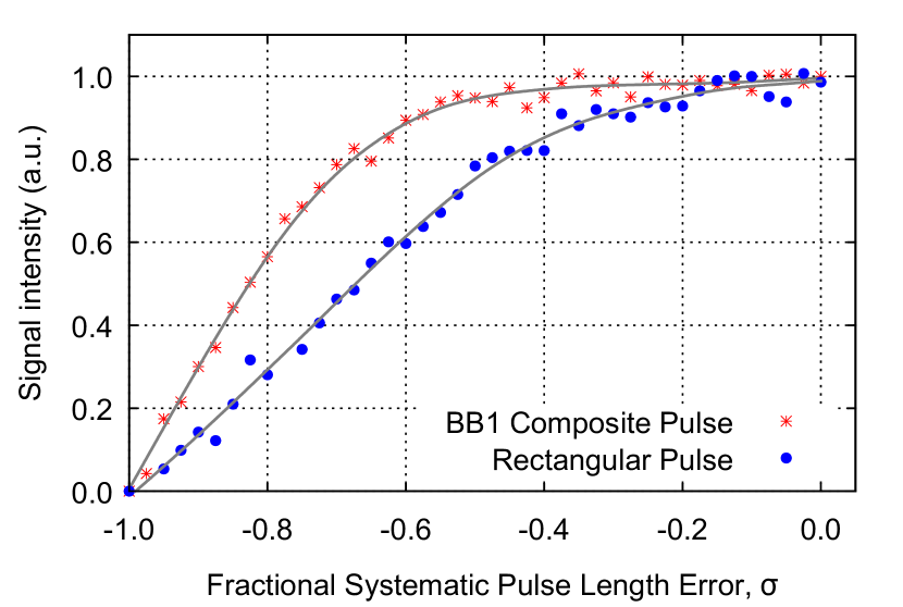
Using deuterated BDPA diluted in PS, pulse length error was intentionally introduced into the spin echo sequence (Eq. 3) by changing the amplitude of the pulse to:
| (4) |
where was caused by the deviation of the pulse amplitude away from its optimal value. This in turn deviated the net magnetization away from the intended rotation and weakened the spin echo signal intensity (see Fig. 2). Next, the experiment was repeated using BB1 composite pulses:
| (5) |
Using Eq. 5, the fractional pulse length error, was reduced and the net magnetization was rotated closer to the intended rotation angle. This produced stronger spin echo signal intensities which only decreased to a ratio of around 0.97 even when (see Fig. 2). This result indicated that high fidelity rotations were achieved when BB1 composite pulses were used and the results were consistent with the simulated performance of BB1 composite pulse in Ref. 39.
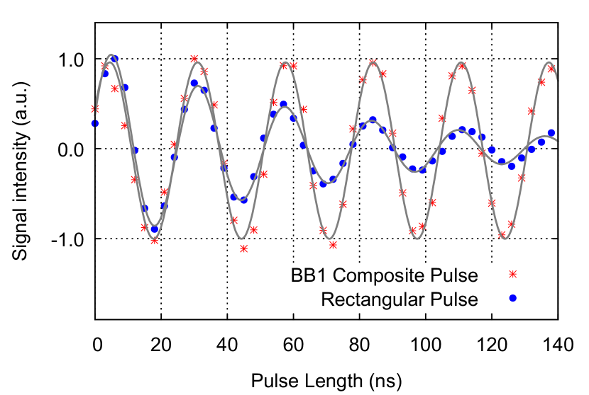
Next, we investigated the intrinsic pulse length errors that accumulated at large rotation angles (up to ) without introducing additional errors. To do this, we compared the spin nutation obtained using normal and BB1 composite pulses. We observed that the Rabi oscillation decayed exponentially when normal pulses were used (see Fig. 3). To correct pulse length errors, the following BB1 pulse sequence was used:
| (6) |
where was varied from 0 to and padded with where is the number of repetitions required to achieve rotation angles larger than . By comparing the spin nutation results obtained from normal and BB1 composite pulses, we found that the exponential decay in the spin nutation was reduced significantly when BB1 pulses were used (see Fig. 3). In this experiment, since the spin-lattice relaxation time, was longer than the experiment time, it did not contribute to the spin nutation exponential decay. When BB1 composite pulses were used, the spin nutation decay was minimized significantly. This confirmed that the Rabi oscillation decayed due to pulse length errors, which were corrected when BB1 composite pulses were used.
For both BB1 experiments, diluted deuterated BDPA was used. Undeuterated, pure BDPA linewidth was around 0.5–1 G (approx. 1.4–2.8 MHz) and the relaxation times were around 100 ns.Goldsborough, Mandel, and Pake (1960); Mitchell et al. (2011); Blank et al. (2003) While the linewidth of undeuterated BDPA was beneficially narrow for our experiments, the short relaxation times were undesirable. Since BDPA narrow linewidth and its short relaxation times were due to its strong exchange interaction,Goldsborough, Mandel, and Pake (1960) diluting the sample weakened the exchange interaction and produced a sample with broader linewidth. By using a deuterated version of the diluted sample, hyperfine interaction was also reduced. As a result, the diluted deuterated sample has a spin-spin relaxation time, of around 200 ns and a linewidth of 9.35 MHz. For the BB1 experiments, the pulse peak power was around 250 mW (24 dBm) and the corresponding Rabi frequency was 38.46 MHz (around 4 times higher than the linewidth of the sample). The time was 300 ns and the duration of , and pulses were 6.5 ns, 13 ns and 26 ns, respectively.
III.2 Fast, multi-frequency modulation at low power
For molecular-spin quantum computers, well-resolved multi-frequency pulses (also known as a frequency comb) can selectively control multiple qubits defined in the frequency-space.Lloyd (1993) In our previous work, we demonstrated a coherent, triple-frequency excitation that spanned over 8 MHz using spin echo pulses. The pulses were consisted of a triple-frequency, shaped pulse and a rectangular pulse.Yap et al. (2015) The excitation was limited by the bandwidth of the resonator, which made it insufficient for real applications. Hence, in this work, we have increased the bandwidth and number of excitations to span over the entire spectrum of the (undeuterated) diluted BDPA.
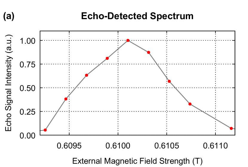
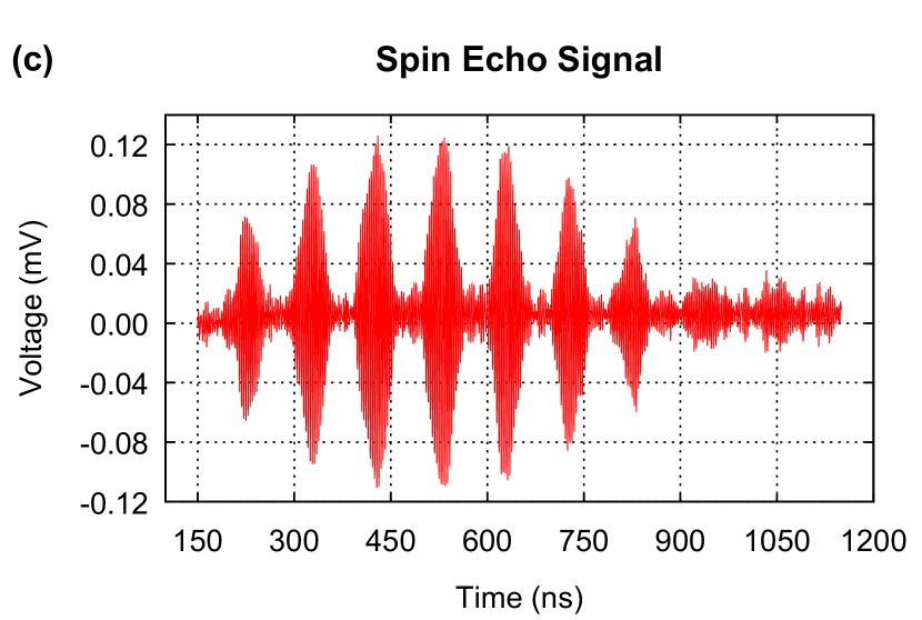
Firstly, the full spectrum of the sample was obtained by sweeping the external magnetic field while an on-resonance, single-frequency Gaussian spin echo pulse was applied (see Fig. 4 (a) for the spectrum). Next, the multi-frequency pulses were calculated by superimposing several single-frequency, Gaussian pulses. This method was applied to both and pulses where their respective Gaussian profiles were calculated based on the duration and power of the rectangular pulses. The respective rectangular pulse lengths for and pulses were 215.5 ns and 431.0 ns. The pulse peak power was 0.29 mW and the corresponding Rabi frequency was 1.16 MHz. The full-width at half maximum (FWHM) duration for a single-frequency Gaussian and pulses were 203.0 ns and 401.7 ns, respectively.
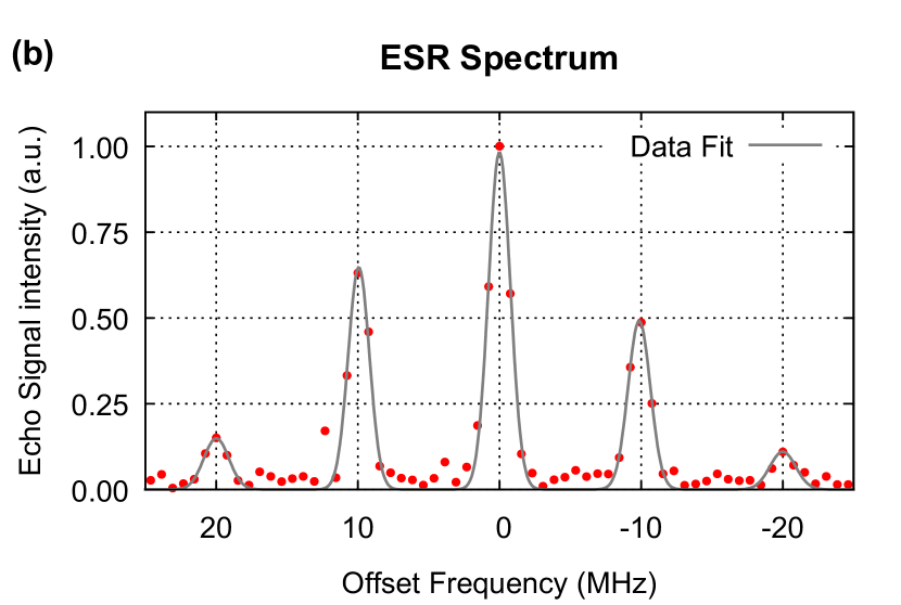
Pulses consisting of five frequencies were calculated and applied at the center frequency of the spectrum (i.e. at its corresponding magnetic field). Well-resolved excitations were obtained for all five offset frequencies: -20, -10, 0, 10 and 20 MHz, which spanned over the entire spectrum of the sample (Fig. 4 (b)). The interference pattern in the spin echo signal was a clear indication that the spin packets were excited coherently. Furthermore, this was achieved with a peak power of 0.29 mW (approximately -5.4 dBm) entering the resonator (after subtracting losses from cables connecting the power amplifier to the resonator).
IV Summary
We have described experiments at room temperatures using an advanced spectrometer capable of generating arbitrary waveform pulses and a new broad bandwidth resonator which featured a large homogeneous sample volume and without sacrificing too much efficiency. With this setup, we experimented with BB1 composite pulse to correct pulse length errors for a broad linewidth sample and also implemented a microwave frequency comb to excite spin packets over the entire spectrum of the sample. Both of these experiments are important examples of arbitrary amplitude and phase modulation towards the development of a molecular spin-based quantum computer.
For the BB1 composite pulses, two experiments were performed at a pulse power of 24 dBm (corresponding Rabi frequency was 38.46 MHz) on a sample with a linewidth of 9.35 MHz. In the first experiment, errors were introduced by changing the pulse amplitude of the spin echo pulse sequence away from its optimal amplitude. In the second experiment, BB1 composite pulse was applied to correct the intrinsic experimental errors (without introducing additional errors). For both experiments, we found that the BB1 composite pulse performed well to correct pulse length errors despite the sample broad linewidth. Previous reports of BB1 experiments were performed only on narrow linewidth ESR samples (such as N@C60 or enriched 28Si:P) or a single spin, where off-resonance effects due to inhomogeneous broadening were negligible. Morton et al. (2005, 2008); Said and Twamley (2009); Wu et al. (2013) Except for a simulation work Ishmuratov and Baibekov (2016), as far as we know, there are no experimental reports on the effectiveness of BB1 composite pulse on a broad linewidth sample as demonstrated here.
For the multi-frequency excitation experiment, we applied a microwave frequency comb and excited five different spin packets simultaneously and coherently. We obtained well-resolved excitations spanning over the entire spectrum of the sample ( 20 MHz) using shaped and pulses. This approach is useful for controlling specific qubits without affecting the remaining qubits. In the quest to build a universal quantum computer, controlling qubits (defined in the frequency-domain) typically involves utilizing several dedicated lines/wires for each qubit/frequency and as the number of qubits increases, the required number of control lines increases as well. Kelly et al. (2015) This ultimately poses a scalability problem when working with a large number of qubits cooled in a dilution refrigerator. Although, the proposed approach would require additional time and effort to numerically design the multi-frequency pulses, it may provide an alternative and efficient solution to this problem.
Acknowledgements.
The authors would like to thank Assoc. Prof. Dr. Chihiro Yamanaka of Osaka University for his technical assistance. This work was supported by Japan Science and Technology Agency (JST), CREST program (JST grant number JPMJCR1672), PRESTO program (JST grant number JPMJPR1666), the Ministry of Education, Culture, Sports, Science and Technology (MEXT) Grant-in-Aid for Scientific Research on Innovative Areas 21102004, the Funding Program for World-Leading Innovating R&D on Science and Technology (FIRST program) and JSPS KAKENHI program (Grant Number JP18H01152). Y.S.Y was also financially supported by Fundamental Research Grant Scheme (FRGS), Malaysia (FRGS/1/2018/STG02/UTM/02/15), Ministry of Education (MOE) and UTM (R.J130000.7854.5F027). The authors would like to acknowledge contributions by Dr. Y. Tabuchi and K. Sowa at the early stages of the work.References
- Arute et al. (2019) F. Arute, K. Arya, R. Babbush, D. Bacon, J. C. Bardin, R. Barends, R. Biswas, S. Boixo, F. G. Brandao, D. A. Buell, et al., “Quantum supremacy using a programmable superconducting processor,” Nature 574, 505–510 (2019).
- Heinsoo et al. (2018) J. Heinsoo, C. K. Andersen, A. Remm, S. Krinner, T. Walter, Y. Salathé, S. Gasparinetti, J.-C. Besse, A. Potočnik, A. Wallraff, et al., “Rapid high-fidelity multiplexed readout of superconducting qubits,” Physical Review Applied 10, 034040 (2018).
- Mehring and Mende (2006) M. Mehring and J. Mende, “Spin-bus concept of spin quantum computing,” Physical Review A 73, 052303 (2006).
- Hodges et al. (2008) J. S. Hodges, J. C. Yang, C. Ramanathan, and D. G. Cory, “Universal control of nuclear spins via anisotropic hyperfine interactions,” Physical Review A 78, 010303 (2008).
- Morton et al. (2008) J. J. Morton, A. M. Tyryshkin, R. M. Brown, S. Shankar, B. W. Lovett, A. Ardavan, T. Schenkel, E. E. Haller, J. W. Ager, and S. Lyon, “Solid-state quantum memory using the 31 p nuclear spin,” Nature 455, 1085 (2008).
- Sessoli et al. (2018) R. Sessoli, M. Atzori, L. Sorace, S. Carretta, A. Chiesa, E. Morra, and M. Chiesa, “A two-qubit molecular architecture for electron-mediated nuclear quantum simulation,” Chemical Science (2018).
- Yap et al. (2015) Y. S. Yap, Y. Tabuchi, M. Negoro, A. Kagawa, and M. Kitagawa, “A Ku band pulsed electron paramagnetic resonance spectrometer using an arbitrary waveform generator for quantum control experiments at millikelvin temperatures,” Review of Scientific Instruments 86, 063110 (2015).
- Morley et al. (2010) G. W. Morley, M. Warner, A. M. Stoneham, P. T. Greenland, J. Van Tol, C. W. Kay, and G. Aeppli, “The initialization and manipulation of quantum information stored in silicon by bismuth dopants,” Nature Materials 9, 725 (2010).
- Tateishi et al. (2014) K. Tateishi, M. Negoro, S. Nishida, A. Kagawa, Y. Morita, and M. Kitagawa, “Room temperature hyperpolarization of nuclear spins in bulk,” Proceedings of the National Academy of Sciences 111, 7527–7530 (2014).
- Ross (2001) R. G. Ross, Cryocoolers 11 (Springer, 2001).
- DiVincenzo (2000) D. P. DiVincenzo, “The physical implementation of quantum computation,” Fortschritte der Physik 48, 771 (2000).
- Jones et al. (2012) N. C. Jones, R. Van Meter, A. G. Fowler, P. L. McMahon, J. Kim, T. D. Ladd, and Y. Yamamoto, “Layered architecture for quantum computing,” Physical Review X 2, 031007 (2012).
- Cummins and Jones (2000) H. Cummins and J. Jones, “Use of composite rotations to correct systematic errors in NMR quantum computation,” New Journal of Physics 2, 6 (2000).
- Cummins, Llewellyn, and Jones (2003) H. K. Cummins, G. Llewellyn, and J. A. Jones, “Tackling systematic errors in quantum logic gates with composite rotations,” Physical Review. A 67 (2003).
- Morton et al. (2005) J. J. Morton, A. M. Tyryshkin, A. Ardavan, K. Porfyrakis, S. Lyon, and G. A. D. Briggs, “High fidelity single qubit operations using pulsed electron paramagnetic resonance,” Physical review letters 95, 200501 (2005).
- Motion et al. (2017) C. L. Motion, S. L. Cassidy, P. A. Cruickshank, R. I. Hunter, D. R. Bolton, H. El Mkami, S. Van Doorslaer, J. E. Lovett, and G. M. Smith, “The use of composite pulses for improving deer signal at 94 ghz,” Journal of Magnetic Resonance 278, 122–133 (2017).
- Doll and Jeschke (2014) A. Doll and G. Jeschke, “Fourier-transform electron spin resonance with bandwidth-compensated chirp pulses,” Journal of magnetic resonance 246, 18–26 (2014).
- Spindler et al. (2012) P. E. Spindler, Y. Zhang, B. Endeward, N. Gershernzon, T. E. Skinner, S. J. Glaser, and T. F. Prisner, “Shaped optimal control pulses for increased excitation bandwidth in EPR,” Journal of magnetic resonance 218, 49–58 (2012).
- Pribitzer, Doll, and Jeschke (2016) S. Pribitzer, A. Doll, and G. Jeschke, “SPIDYAN, a MATLAB library for simulating pulse EPR experiments with arbitrary waveform excitation,” Journal of Magnetic Resonance 263, 45–54 (2016).
- Kaufmann et al. (2013) T. Kaufmann, T. J. Keller, J. M. Franck, R. P. Barnes, S. J. Glaser, J. M. Martinis, and S. Han, “Dac-board based X-band EPR spectrometer with arbitrary waveform control,” Journal of Magnetic Resonance 235, 95–108 (2013).
- Doll et al. (2013) A. Doll, S. Pribitzer, R. Tschaggelar, and G. Jeschke, “Adiabatic and fast passage ultra-wideband inversion in pulsed EPR,” Journal of Magnetic Resonance 230, 27–39 (2013).
- Spindler et al. (2013) P. E. Spindler, S. J. Glaser, T. E. Skinner, and T. F. Prisner, “Broadband inversion PELDOR spectroscopy with partially adiabatic shaped pulses,” Angewandte Chemie International Edition 52, 3425–3429 (2013).
- Dolde et al. (2014) F. Dolde, V. Bergholm, Y. Wang, I. Jakobi, B. Naydenov, S. Pezzagna, J. Meijer, F. Jelezko, P. Neumann, T. Schulte-Herbrüggen, et al., “High-fidelity spin entanglement using optimal control,” Nature communications 5, 3371 (2014).
- Scherer and Mehring (2008) W. Scherer and M. Mehring, “Entangled electron and nuclear spin states in 15N@C60: Density matrix tomography,” The Journal of chemical physics 128, 052305 (2008).
- Vandersypen and Chuang (2005) L. M. Vandersypen and I. L. Chuang, “Nmr techniques for quantum control and computation,” Reviews of modern physics 76, 1037 (2005).
- Lloyd (1993) S. Lloyd, “A potentially realizable quantum computer,” Science 261, 1569–1571 (1993).
- Morita et al. (2010) Y. Morita, Y. Yakiyama, S. Nakazawa, T. Murata, T. Ise, D. Hashizume, D. Shiomi, K. Sato, M. Kitagawa, K. Nakasuji, et al., “Triple-stranded metallo-helicates addressable as lloyd’s electron spin qubits,” Journal of the American Chemical Society 132, 6944–6946 (2010).
- Shane et al. (1998) J. Shane, I. Gromov, S. Vega, and D. Goldfarb, “A versatile pulsed X-band ENDOR spectrometer,” Review of scientific instruments 69, 3357–3364 (1998).
- Tseitlin et al. (2011) M. Tseitlin, R. W. Quine, G. A. Rinard, S. S. Eaton, and G. R. Eaton, “Digital epr with an arbitrary waveform generator and direct detection at the carrier frequency,” Journal of magnetic resonance 213, 119–125 (2011).
- Conway Lamb et al. (2016) I. Conway Lamb, J. Colless, J. Hornibrook, S. Pauka, S. Waddy, M. Frechtling, and D. Reilly, “An fpga-based instrumentation platform for use at deep cryogenic temperatures,” Review of Scientific Instruments 87, 014701 (2016).
- Said and Twamley (2009) R. Said and J. Twamley, “Robust control of entanglement in a nitrogen-vacancy center coupled to a c 13 nuclear spin in diamond,” Physical Review A 80, 032303 (2009).
- Wu et al. (2013) H. Wu, E. M. Gauger, R. E. George, M. Möttönen, H. Riemann, N. V. Abrosimov, P. Becker, H.-J. Pohl, K. M. Itoh, M. L. Thewalt, et al., “Geometric phase gates with adiabatic control in electron spin resonance,” Physical review A 87, 032326 (2013).
- Hyde, Froncisz, and Oles (1989) J. S. Hyde, W. Froncisz, and T. Oles, “Multipurpose loop-gap resonator,” Journal of Magnetic Resonance (1969) 82, 223–230 (1989).
- Yap et al. (2013) Y. S. Yap, H. Yamamoto, Y. Tabuchi, M. Negoro, A. Kagawa, and M. Kitagawa, “Strongly driven electron spins using a Ku band stripline electron paramagnetic resonance resonator,” Journal of Magnetic Resonance 232, 62–67 (2013).
- Twig, Suhovoy, and Blank (2010) Y. Twig, E. Suhovoy, and A. Blank, “Sensitive surface loop-gap microresonators for electron spin resonance,” Rev. Sci. Instrum. 81, 104703 (2010).
- dur (2017) RT/duroid 5870/5880 High Frequency Laminates, Rogers Corporation, Advanced Connectivity Solutions 100 S. Roosevelt Avenue, Chandler, AZ 85226 (2017).
- dur (2010) RT/duroid 6035HTC High Frequency Laminate, Rogers Corporation, Advanced Circuit Materials Division, 100 S. Roosevelt Avenue, Chandler, AZ 85226 (2010).
- Labelle, Limb, and Gleason (1997) C. B. Labelle, S. J. Limb, and K. K. Gleason, “Electron spin resonance of pulsed plasma-enhanced chemical vapor deposited fluorocarbon films,” Journal of applied physics 82, 1784–1787 (1997).
- Wimperis (1994) S. Wimperis, “Broadband, narrowband, and passband composite pulses for use in advanced NMR experiments,” Journal of Magnetic Resonance, Series A 109, 221–231 (1994).
- Goldsborough, Mandel, and Pake (1960) J. Goldsborough, M. Mandel, and G. Pake, “Influence of exchange interaction on paramagnetic relaxation times,” Physical Review Letters 4, 13 (1960).
- Mitchell et al. (2011) D. G. Mitchell, R. W. Quine, M. Tseitlin, R. T. Weber, V. Meyer, A. Avery, S. S. Eaton, and G. R. Eaton, “Electron spin relaxation and heterogeneity of the 1: 1 , -bisdiphenylene--phenylallyl (bdpa)/benzene complex,” The Journal of Physical Chemistry B 115, 7986–7990 (2011).
- Blank et al. (2003) A. Blank, C. R. Dunnam, P. P. Borbat, and J. H. Freed, “High resolution electron spin resonance microscopy,” Journal of Magnetic Resonance 165, 116–127 (2003).
- Ishmuratov and Baibekov (2016) I. Ishmuratov and E. Baibekov, “Bulk quantum computation with pulsed electron paramagnetic resonance: simulations of single-qubit error correction schemes,” Journal of Low Temperature Physics 185, 583–589 (2016).
- Kelly et al. (2015) J. Kelly, R. Barends, A. G. Fowler, A. Megrant, E. Jeffrey, T. C. White, D. Sank, J. Y. Mutus, B. Campbell, Y. Chen, et al., “State preservation by repetitive error detection in a superconducting quantum circuit,” Nature 519, 66 (2015).