BEH: Indoor Batteryless BLE Beacons using RF Energy Harvesting for Internet of Things
Abstract
Indoor beacon system is a cornerstone of internet of things. Until now, most of the research effort has focused on achieving various applications based on beacon communication. However, the power consumption on beacon devices becomes the bottleneck for the large-scale deployments of indoor networks. On one hand, the size of beacon devices is required to be small enough for easy deployment, which further limits the size of battery. On the other hand, replacing the batteries of the beacon devices could lead to high maintenance costs. It is important to provide them with full energy autonomy. To tackle this problem we propose BEH: an indoor beacon system aimed at operating perpetually without batteries. Our contributions are twofold. Firstly, we propose four methods to increase the utilization efficiency of harvested RF energy in the beacon system, by which the energy consumption level becomes low enough to fit within the energy harvesting budget. Secondly, we implement BEH using Bluetooth Low Energy (BLE) and Radio Frequency (RF) energy harvesting devices, and test BEH extensively in a laboratory environment. Our test results show that BEH can enable perpetual lifetime operation of mobile and static BLE beacon devices in a (16 m) room. The average value of packet reception rate achieves more than 99% in the best case.
I Introduction
Beacon communication is widely adopted as one of the key technologies for Internet of Things (IoT) applications requiring low energy consumption and low data rate. Among various beacon schemes, Bluetooth Low Energy (BLE) beacon is one of the most promising systems for indoor applications. Its main advantages are low power consumption and simple implementation. Integrating BLE beacon into IoT devices promotes various applications, including localization [1], proximity detection [2], activity sensing [3], smart offices [4], etc.
Along with the large-scale deployment, the maintainability in the life cycle of BLE beacon system raises as an important evaluation index, including deploying, replacing battery, repairing, etc. In some large-scale scenarios, the cost for replacing the batteries of thousands of beacon nodes would be too high. For example, Amsterdam Schiphol Airport has roughly 10000 BLE beacons deployed to provide navigation services. In some other scenarios, such as smart infrastructures with beacon devices embedded in the materials themselves, battery replacement would be even impossible.
The research community has recognized this energy autonomous challenge, meanwhile the area of Energy Harvesting (EH) starts to gain momentum [5][6]. To mitigate the power supply issue, various energy harvesting techniques are integrated with IoT devices. However, most existing energy harvesting solutions rely on specific application scenarios. For example, solar panel is mainly used for harvesting outdoor sunlight or indoor lighting. Kinetic energy harvesting targets on mobile users or objects. These energy harvesting systems cannot supply continuous harvested energy for perpetual operation of devices. We need an energy harvesting solution for BLE beacon applications, which can (i) be deployed for indoor area; (ii) operate 24 hours without interrupting the daily life of users; (iii) supply enough energy for periodical BLE beacon communication. Among the existing EH techniques [5], we chose the one based on radio frequency (RF).
In this paper, we build an indoor batteryless BLE beacon system using RF energy harvesting named BEH. Dedicated RF sources are deployed to radiate radio energy to the neighbor BLE beacon devices. The main aim of BEH is that the static and mobile beacon devices rely on harvested RF energy to achieve beacon communication and proximity detection. Specifically, the mobile device initiates the beacon procedure by broadcasting a beacon request message to the neighbor static BLE beacon nodes. The static beacon nodes send beacon reply messages back to the mobile devices after receiving the request. We require: (i) the mobile device can successfully receive the reply messages from static beacon nodes, and correctly decode the packet information. (ii) the mobile device localizes itself to the proximity position of the beacon node sending the beacon reply with the strongest signal strength.
To achieve these aims, we make four innovations in the system design and implementation. Firstly, we propose a collision based beacon approach based on capture effect and orthogonal code. The approach minimizes the power consumption of receiving beacon messages in mobile devices. Secondly, RF-based passive wake-up is utilized and optimized to decrease the power consumption of idle listening and unnecessary wake-up in static beacon nodes. Thirdly, we make RF energy based proximity range estimation to mobile nodes, and wakes up the static beacon nodes which are nearby the mobile device to send beacon reply messages. The approach avoids unnecessary wake-up and beacon communication in static beacon nodes. Fourthly, we propose a two-wave beacons approach to cope with the unbalanced harvested energy in static beacon nodes. The approach increases the energy utilization efficiency of static beacon nodes that harvest lower energy.
BEH system can be used for sending information, such as sensing data, from static beacon nodes to mobile devices. The mobile devices can estimate its proximity position while receiving beacon information. We evaluate the performance of BEH by packet reception rate (PRR) and proximity detection accuracy (PDA). We aim to achieve high PRR, while relax the requirement on PDA. We require PDA can provide mobile devices at least room level accuracy. The trade-off between PRR and PDA is not the aim of BEH.
To summarize, we make the following contributions.
-
1.
To the best of our knowledge, BEH is the first IoT system that successfully achieves bidirectional BLE beacon communication and proximity detection using the RF based energy harvesting.
- 2.
-
3.
We systematically evaluate the system in an office environment. As a result, BEH achieves perpetual beacon communication and proximity detection on batteryless devices. Some experimental results are shown in Tab.I.
| Property | Test Results |
|---|---|
| Min. beacon period | 1 s |
| Max. density of static beacon nodes | 0.25 node per m2 |
| Max. range from energy source to beacon devices | 4 m |
| Avg. PRR (0.0625 static beacon node per m) | |
| Avg. PDA (0.0625 static beacon node per m) | |
| Avg. PRR (0.25 static beacon node per m) | |
| Avg. PDA (0.25 static beacon node per m) |
-
•
Tx Power of BLE is 0 dBm. Tx Power of RF energy transmitter is 3 W(EIRP). The antenna of RF energy harvester is vertical polarized patch antenna with 6.1 dBi gain.
The rest of the paper is organized as follows. The background of RF based energy harvesting is introduced in Sec. II. The related work is discussed in Sec. III. The problem and solution is discussed in Sec. IV. The system model, including the hardware definition, operation procedure and evaluation metrics are listed in Sec. V. In Sec. VI, we explain the four key components of our system design in detail. We present our implementation of software and hardware in Sec. VII. Experimental results and analysis are presented in Sec. VIII. Finally, we present the future work and our conclusions in Sec. IX and Sec. X.
II Background of RF Energy Harvesting
| Pin Label | Function |
|---|---|
| Voltage of harvested RF energy after RF-DC converter. | |
| Analog voltage level corresponding to harvested power. | |
| DC Output of harvested power. | |
| Set to enable measuring harvested power. | |
| Threshold value of for charging and discharging. |
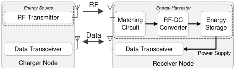
The basic architecture of RF energy harvesting and data communication used in BEH is shown in Fig.1. The data communication channel is in parallel with RF energy harvesting. The energy used for the data transceiver in receiver node is from energy harvesting. The core component in the energy harvester is RF-DC converter. It is used to rectify radio wave into directional current. Generally, it consists of band-pass filter, rectifier, and low-pass filter [9]. The energy harvester boosts the voltage of the harvested power to the required level, and stores in capacitor for power supply of data transceiver.
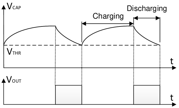
We utilize P2110 Powerharvester of Powercast [8] as the RF energy harvester. There are five pins of P2110 used for BEH as shown in Tab. II. When the voltage of harvested power from is above the threshold in the capacitor, the voltage is boosted and the voltage output is enabled. When declines below the threshold , is turned off. A brief time diagram of the charging and discharging process is shown in Fig.2. The time duration and frequency when has voltage output depends on the speed of charging and discharging. samples the analog voltage signal of harvested power to provide an indication of the amount of energy being harvested.
The harvested RF energy is limited and easily affected by environmental factors, such as interference, obstacles, etc [10]. To the best of our knowledge, there is not simulation model, which can accurately simulate all the factors affecting RF energy harvesting. Therefore, we implement BEH in hardware and test in real deployment fields.
III Related Work
IoT system is typically used for industry automation, healthcare, surveillance, smart cities, etc. One of the bottlenecks for large-scale deployment is supplying adequate energy to IoT devices for long or even perpetual lifetime. There is much research about energy utilization efficiency and energy autonomous for IoT systems.
III-A RF-based Energy Harvesting
To mitigate the power supply issues for the large-scale deployment of IoT devices, energy autonomous for IoT attracts much research work [11]. In the research field of energy-autonomous systems, many kinds of techniques are explored as energy sources, including solar panels [12], wind [13], vibration [14], RF radio [15], magnetic resonance [16], ultra-sound [17], etc.
RF-based energy harvesting systems can be classified into subcategories [6], including omni-directional or directional energy harvesting antenna, single or multi hop wireless charging [18], static or mobile charger networks [19], parallel or simultaneous wireless information and power transfer [20] [21], ambient or dedicated RF energy harvesting [15], etc.
To implement an RF-based energy harvesting system, the first and most important factor is the type of RF energy source: ambient or dedicated RF energy harvesting. In the case of ambient RF energy source, the devices harvest ambient RF energy. The source of RF energy is not deployed purposely for energy harvesting, such as TV tower, wifi router, mobile base station, etc. In the case of dedicated RF energy harvesting, dedicated RF sources are deployed to transmit radio energy to the area where IoT devices require wireless energy [15].
The advantage of ambient RF energy harvesting is that there is no need to deploy specific energy sources; therefore, the deployment range of the energy harvesting devices is large. Compared with ambient RF energy harvesting, dedicated RF energy harvesting allows nearby devices to harvest more power. Because the energy source is dedicated to transmit RF power, and the radio properties of RF energy sources can be tuned to adapt to the energy requirements of energy harvesters, such as Tx power, frequency, etc. However, the disadvantage is that energy harvesting devices must be kept inside the effective power transmission range of the energy sources, which limits the mobility range of energy harvesting devices. In addition, the setup of RF energy sources must guarantee that the available RF power beamed on the mobile users is below the regulated safety bound [10]. Based on our requirements on the BLE beacon applications, RF-based energy harvesting with dedicated RF energy sources is the most suitable choice.
III-B BLE Beacon Applications
BLE system is widely adopted for resource constrained IoT applications, such as indoor localization and tracking [1], proximity detection [2], activity sensing [3], smart offices [4], and so on. One of the main reasons is that BLE beacon communication consumes low energy and is simple to implement [22]. Therefore, BLE beacon becomes an ideal communication protocol to use energy harvesting. Much research combines BLE beacon based applications with energy harvesting techniques. [23] analyzes the systems that harvest lighting energy for indoor energy constraint applications. The analysis is based on various design choices, including photovoltaic cell, power conditioning circuit, energy storage, etc. [24] designs and implements an indoor wireless sensor system using lighting-based energy harvesting. It proposes maximum power point tracking circuit, which increases the power conversion efficiency in solar cells. The lifetime of the system largely increases from less than 6 months to more than 10 years. [25] proposes a BLE based hardware design that operates entirely on harvested energy. Its energy mainly relies on dual ISM-band RF sources and partially on photovoltaic energy harvesting. The system achieves periodical beacon advertising with interval of 45s.
III-C Localization with RFID
Radio-frequency identification (RFID) tags harvest RF energy from the electromagnetic field of nearby RFID readers. It is widely used to automatically identify and track tags. Localization based on RFID technology is developing rapidly in recent years. These approaches can be classified into three categories [26]. In the first category, RFID reader-based localization system, e.g. [27, 28], allocates RFID reader in the object requiring localization to detect the pre-deployed anchor tags nearby. Although the deployment and maintenance cost of RFID tags are low, the localization lifetime depends on the limited battery of mobile readers. In the second category, RFID tag-based localization system, e.g. [29, 30], tracks the location of object attached with RFID tag by pre-deployed readers. The advantage of this approach is that the lifetime of tags is unlimited. However, the localization range is limited by the density of readers. Also, the tags cannot be localized once they are outside the range of readers. In the last category, RFID device-free localization system, e.g. [31], detects the position of target wearing no additional localization devices. The idea is to find the target location by detecting and comparing the change of RFID signal in the environment.
III-D Computational RFID (C-RFID)
C-RFID is a RFID system with computational unit on RFID tag. It is applied in various wireless sensor applications [32] [33]. Wireless Identification and Sensing Platform (WISP) [34] is the most mature system among all the C-RFID research. It uses the industrial standard EPCglobal Class 1 Generation 2 (EPC C1G2) RFID protocol. The main drawback of C-RFID is its intermittent power supply [35], which drags down the computing and communication performance of the entire system.
| Property | BLE | RFID | C-RFID | BEH |
|---|---|---|---|---|
| Data Processing | Yes | No | Yes | Yes |
| Battery | Yes | No | No | No |
| Energy Harvesting Source | No | Yes | Yes | Yes |
| Backscatter Radio | No | Yes | Yes | No |
| High Bound of Data Rate | High | Low | Low | High |
III-E Comparison
We compare the properties between BLE, RFID, C-RFID, and our BEH as shown in Tab.III. Compared with BLE, BEH achieves BLE beacon operation without battery. The shortcoming of BEH is mainly twofold. Firstly, BEH system requires RF energy transmitters are deployed around the BEH beacon devices, which limits the scalability of deployment. Secondly, the communication speed of BEH depends on the amount of harvested energy. C-RFID and BEH both have data processing unit, batteryless structure, and energy harvesting source. Compared with C-RFID, the key difference of BEH is that its communication does not rely on backscatter radio. The communication and energy harvesting of BEH use different radio frequencies. Intermittent energy radio only affects the harvested energy and communication speed of BEH, while its communication quality is comparable to BLE communication as long as the harvested energy is enough. In addition, when the harvested energy is high, e.g. the BEH device is close to RF energy source, the high bound of data rate using BEH is much higher than RFID and C-RFID. Moreover, since BEH uses BLE protocol stack for communication, it can be naturally integrated into existing BLE networks, and it can easily control the communication parameters, such as Tx power, to optimize the communication performance.
IV Problem Analysis
Beacon applications and energy harvesting are well researched topics on their own, but using RF-based energy harvesting for BLE beacon applications entails a substantial challenge. The main problem is that the amount of harvested energy from RF energy source is too small for the operation of beacon applications. In this section, we make empirical studies to analyze the challenges and possible solutions to achieve BLE beacon applications using RF-based energy harvesting.
IV-A Choose RF-based Energy Harvesting
While many energy harvesting techniques exist [5], such as solar energy harvesting, kinetic energy harvesting from human movement, indoor light harvesting, etc., we chose the one based on RF energy harvesting (RF-EH) with dedicated energy source. In this type of system, dedicated RF energy transmitters are deployed at specific positions. They continuously radiate radio energy to the neighbor RF energy harvesting devices. Compared with the other EH solutions, RF-EH with dedicated energy source has the following advantages.
-
•
The operation of dedicated RF energy source does not rely on environment or users. For example, although indoor lighting harvesting is feasible for indoor BLE beacon applications, the harvested energy depends on the environmental lighting strength.
-
•
The transmitted power of dedicated RF energy source can be adjusted based on the requirement. The harvested energy can be estimated based on the distance between RF energy transmitters and harvesters.
-
•
To harvest the required amount of energy, the size of the RF energy harvesting device is small enough to attach on beacon devices.
-
•
Proximity detection is an important function in beacon applications. RF energy source can not only serve for transmitting RF energy, but also provide distance estimation between energy transmitter and receiver based on the harvested energy. This property can help to improve the performance of beacon based proximity detection.
| Operation | Current |
|---|---|
| Standby (ON mode) | 2.6 A |
| Run code from RAM at 16 MHz | 2.4 mA |
| Transmitting (4dBm) | 11.8 mA |
| Receiving | 9.7 mA |
-
•
Voltage supply range from 1.8 V to 3.6 V.
IV-B Energy Requirement and Energy Budget
To understand the challenges on BLE beacons using harvested RF energy, we measure and analyze the basic performance of BLE beacons and RF energy harvesting implemented by off-the-shelf devices.
IV-B1 Energy Consumption
To assess the energy demand of BLE beacon devices, we use BLE beacon device nRF51822 [36]. In the first place, we analyze the power consumption of its basic operations as shown in Tab.IV. As expected, the current on data transmitting and receiving is much higher than the other operations. The energy consumption on receiving is 3731 times larger than standby mode under the same voltage supply and time duration. This means that it will save much energy by setting the idle listening to standby mode.
To further understand the energy consumption of BLE devices, we use Monsoon power meter [37] to measure the power consumption and the time duration of sending and receiving BLE packets. Firstly, we set up an auxiliary BLE device. It listens to the communication channel in full time. Once receiving a packet, it sends back a packet of the same size. Secondly, we set up a measuring BLE device. It wakes up from sleeping mode and sends a packet. Then it listens to the communication channel and receives a packet from the auxiliary device. After receiving the packet, it returns to sleep mode. Fig 3(a) shows the energy consumption of the measuring BLE device in various packet sizes.
IV-B2 Harvested RF Energy
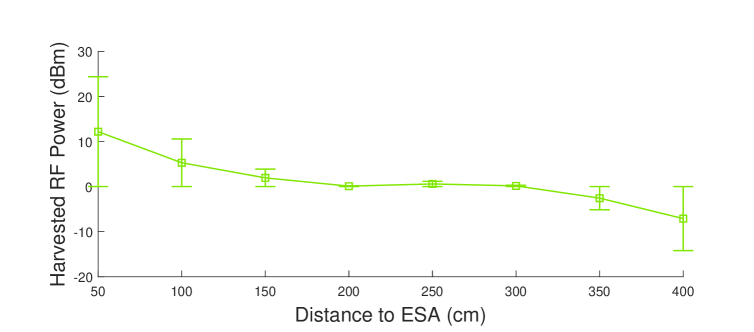
To assess the energy supply, we measure the harvested energy using off-the-shelf RF-based wireless power transfer product Powercast [8]. The RF energy transmitter has an Effective Isotropic Radiated Power (EIRP) of 3 W and operates at a center frequency of 915 MHz. We measure the harvested power (before the voltage booster) of Powercast P2110 receiver [38] with a 0.5 k load at various distances. Fig 3(b) shows the harvested energy in 100 ms.
IV-B3 Analysis on Energy
Based on the preliminary experiments above, we have the following observation results.
-
(i)
At a 1 m distance from the RF energy transmitter, more than 350J of energy can be harvested within 100 ms, and the energy consumption from 10 to 100 bytes is no more than 40 J. Therefore, the harvested energy of 100 ms gives sufficient leeway to transmit and receive beacon messages of 40 bytes in a range of 3 meters.
-
(ii)
The harvested energy within 100 ms is not enough for transmitting and receiving packets of one byte at a distance 3.5 m. This issue can be solved by increasing the time duration of RF energy harvesting.
-
(iii)
Due to the exponential decay of RF signal, the harvested energy at 1 m is 36 times larger than at 3.5 m. If beacon nodes with energy harvester are deployed uniformly around the RF energy transmitter, the harvested energy in these beacon nodes will be quite imbalanced. If all these nodes are required to send beacon messages in the same rate, they must wait until the last node harvests enough energy. Therefore, we need a solution to increase the energy utilization efficiency of the beacon devices that are further away from the RF energy transmitter.

IV-C Solution Direction
Based on the analysis above, we find if the harvested RF energy is used efficiently, it is enough to support the power consumption of BLE beacon applications. The key solutions to implement BLE beacon applications using RF energy harvesting are mainly two aspects:
-
•
Decreasing the power consumption of BLE beacon: We must decrease the time length of beacon communication on both sender and receiver. The radio of beacon devices should be kept ON for the minimum amount of time. The beacon receiver must avoid idle listening as much as possible.
-
•
Increasing the efficiency of using harvested RF energy: The beacon request rate must be carefully selected, so that the beacon nodes have enough harvested energy to finish the operation of sending and receiving beacon messages. The beacon devices must decrease the chance of unnecessary wakeup. Since the harvested energy in beacon devices is uneven, we must increase the energy utilization efficiency especially in the “energy-weakest” beacon nodes.
V System Model
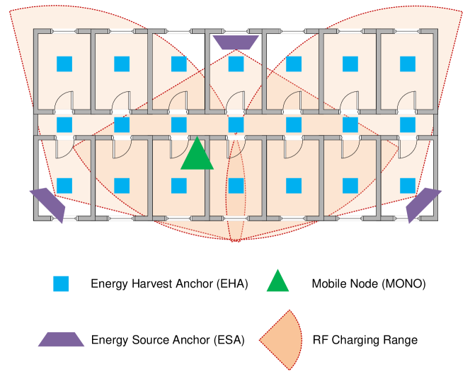
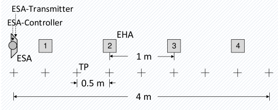
We design three types of nodes in BEH. An example deployment scenario is shown in Fig.4.
-
•
Energy Source Anchor (ESA): ESA consists of two components. The first component is called ESA-Transmitter, which is the dedicated RF energy sources using fixed frequency and Tx power. The second component is ESA-Controller, which is a BLE beacon device attached to ESA-Transmitter for controlling the operation (e.g. energy transmitting ON/OFF) of ESA. ESAs are statically deployed to emit energy to nearby devices. ESA uses fixed power supply via a power cable. Therefore, it is unnecessary to save the communication energy of ESA-Controller. We make ESA-Controller listen to the communication channel in full time.
-
•
Energy Harvesting Anchor (EHA): EHA is a BLE beacon device connected with RF energy harvester. We assume EHAs are uniformly deployed in the center of equally partitioned square cells. Each EHA is pre-programmed with a unique ID representing the location of the square cell where it resides. EHA does not store the harvested RF energy in battery. It directly utilizes the harvested energy for beacon operations.
-
•
Mobile Node (MONO): MONO has the same hardware structure as EHA. It is attached on the mobile user and powered by RF wireless energy. MONO periodically wakes up from sleeping mode and sends beacon request to the neighbor EHAs. We assume that it has a pre-defined table including the position and IDs of EHAs. Once receiving the beacon message of the nearest EHA, the MONO first decodes the EHA ID in the message. Then it uses the pre-defined table to correlate the ID with a location, which represents the present proximity position of itself. MONO does not have batteries, while directly uses harvested energy from nearby RF energy transmitter for beacon operations.
Based on the three types of nodes, we define a round of beacon procedure in BEH as follows.
-
(i)
The ESA constantly transmits RF energy to the nearby space. The MONOs and EHAs harvest RF energy all the time in the effective RF energy range of ESA.
-
(ii)
The MONO periodically broadcasts beacon request to the neighbor ESA.
-
(iii)
The ESA that receives the beacon request notifies the EHAs that are nearby the MONO.
-
(iv)
The EHAs receive the notification from ESA and send beacon reply back to the MONO.
-
(v)
The MONO decodes the content of beacon packet from the nearest EHA, and estimates its own proximity position based on the decoded beacon packet.
We evaluate the performance of BEH beacon procedure by the metrics as follows:
-
•
Packet Reception Rate (PRR): Suppose the MONO sends beacon request periodically. If the MONO successfully receives and decodes the EHA beacon, we record this round of beacon as a success. Otherwise, it is recorded as a failure. PRR is defined as the number of success beacon divided by the number of beacon requests initiated by the MONO. PRR represents the success rate to finish beacon communication.
-
•
Proximity Detection Accuracy (PDA): Suppose the MONO is inside the cell area of EHA and sends beacon request periodically. If the MONO receives and decodes the beacon message from EHA , we record this round of proximity detection as correct. Otherwise, it is recorded as wrong. PDA is defined as the number of correct proximity detection divided by the number of success beacons. PDA represents the correct rate that MONO localize itself in the closest EHA cell.
-
•
Localization Error (LE): Suppose the MONO is inside the cell area of EHA and sends beacon request periodically. If the MONO receives and decodes the beacon message from EHA , we record the localization error of this round of beacon as the distance between EHA and . If this round of proximity detection is correct, the error is zero. LE is calculated as the average value of recorded localization errors. LE is used as a complement index of PDA to illustrate the performance of BEH.
The main aim of BEH system is to achieve a high PRR. Based on this aim, we require PDA has room level accuracy. The trade-off relation between PRR and PDA is not the aim of this research.
VI Key Components to Achieve Bateryless BLE Beacon Using RF Energy Harvesting
In this section, we discuss the key components to achieve batteryless BLE beacon using RF energy harvesting. These components decrease the power consumption of beacon communication and increase the efficiency of utilizing harvested energy, including reducing time length of receiving messages by collision based beacon (Sec.VI-A), reducing idle listening time length by passive wakeup (Sec.VI-B), reducing unnecessary beacons by range estimation (Sec.VI-C), and increase energy utilization efficiency by two wave beacons (Sec.VI-D).
VI-A Collision based Beacon
In this section, we focus on decreasing the power consumption of MONO. We minimize the time length of receiving beacon messages in MONO. We assume EHAs listens to the communication channel in full time in this section. The approach to decrease the idle listening of EHAs is present in the next section (Sec.VI-B).
Most existing communication solutions avoid collisions among packets, such as CSMA/CA and frequency hopping. Although these approaches are quite effective, they involve extra energy consumption for coordinating transmission timing and frequency selection. For example, CSMA/CA requires that the device listens to the channel to confirm whether the channel is free. However, the harvested RF energy is quite limited. According to our measurement, it is only enough for receiving and transmitting for a very short time. There is not enough energy for coordinating time slot and frequency. In addition, when multiple EHAs send beacon messages to a MONO, the MONO still needs to receive the beacon messages from multiple EHAs one after another. However, BEH requires MONO to receive the beacon messages only from the nearest EHA. Therefore, MONO wastes much energy on receiving unnecessary beacon messages by these existing solutions.
Contrary to the existing solutions, we take advantage of ”packet collision” to decrease the operational time of MONO as much as possible. We make all EHAs send their packets at the same time, while MONO leverages the capture effect [39] to decode the strongest signal. The key advantage of this method is its energy efficiency, by which MONO only needs to be active for a single time slot for packet receiving.
VI-A1 Algorithm Design
We present the detail design of collision based beacon as follows, including communication synchronization, orthogonal code, error correction, encoding process, and decoding process.
Communication Synchronization
We make each beacon packet consists of a preamble of one byte, a payload and a CRC of the whole packet. The beacon initiative message from MONO is named as beacon-request, and the reply beacon message as beacon-reply. According to the capture effect, the stronger signal can be decoded, if the second beacon arrives while processing the header of the previous beacon. Therefore, to leverage the capture effect, the packets from multiple EHAs should arrive at MONO within each other’s preamble. This gives us much space to synchronize the beacons from EHAs. The challenges then becomes the synchronization of multiple beacon-reply messages.
On one hand, if we make EHAs wake up in duty cycle mode, they will not receive the beacon-request packet synchronously. Then the capture effect will not work. On the other hand, if the beacon-request packet is used to synchronize the operation of EHAs, EHAs must idle listening the communication channel in full time. This is not applicable due to the limited harvested energy of EHAs. Moreover, although there are many existing synchronization approaches, these synchronization process will consume extra energy.
Therefore, we assume all EHAs are in listening mode in this section. We focus on decreasing the power consumption of MONO, while minimize the power consumption of EHAs in the next section. To achieve this synchronization, the MONO broadcasts a beacon-request packet. The EHAs use this packet as a synchronization signal that instructs all the receiving EHAs to send beacon-reply with the information and their ID encoded in the payload simultaneously.
Orthogonal Spreading Code
Leveraging the capture effect alone however has limitations [40]. For utilizing capture effect, the strongest signal needs a certain minimum signal-to-interference-plus-noise ratio (SINR). If this requirement is not satisfied, packets will collide and the content will not be retrieved. To overcome this limitation the packet payload is encoded with an orthogonal code to increase inter-packet distinction.
Assume the value set size of beacon packet payload is limited, and a unique orthogonal code corresponds to a element in the value set. Take the EHA ID in the payload as an example. Each EHA ID corresponds a unique orthogonal code. In the encoding process at EHA, each bit of the EHA ID is multiplied by an orthogonal code unique for this EHA. The encoded EHA ID is then send in the payload of a packet. The decoding process at MONO is an XOR operation between the payload of received packet with a list of orthogonal codes. Any method can be used as long as the codes all have zero cross-correlation with each other. In this paper a Hadamard matrix of size is used to generate the codes, i.e.,
| (1) |
where , and is the Kronecker product.
In our implementation, we define an orthogonal code for each EHA ID. For simplifying the implementation, we pre-install all the orthogonal codes in MONO before the experiment. The value set of beacon packet payload is all the EHA IDs. The size of the orthogonal code is 16 bits and the total message length is 30 bytes in the payload of the beacon packet.
Forward Error Correcting Code
To further increase the success rate for decoding packet, the EHA ID is first encoded with a Forward Error Correcting (FEC) code, before it is multiplied by the orthogonal codes. The FEC is constructed by maximum minimum Hamming distance codes [41] i.e. codes having equal Hamming distance to each other. The decoding of FEC uses minimum distance decoding.
Encoding Process
All the EHAs have an array of FEC codes with equal Hamming distance to each other. Every EHA ID is FEC encoded by replacing the ID with an unique FEC code from the array. The orthogonal code array is generated using the method described in Sec. VI-A1. For the generated matrix, each symbol is replaced with a and each row of the matrix represents a binary spreading code. Finally, every bit of the FEC code is represented by an unique orthogonal code in the orthogonal code array. If the bit is zero, the bitwise NOT of the orthogonal code is used.
Decoding Process
We assume the MONO has an array of all the orthogonal and FEC codes used by the EHAs. For every entry in the orthogonal code array, the MONO tries to decode the packet. Suppose the EHA ID is encoded inside packet payload. When a candidate EHA ID is found, the decoded code is compared to the correlating FEC code of the candidate ID. Suppose each FEC code has equal Hamming distance to each other. We compare the Hamming distance of the candidate FEC code to a code from the FEC array. If , we assume that the candidate ID is the correct one.
VI-A2 Validity Test
To verify that the collision based beacon works correctly, the following experiment was performed. We select the Smart BLE Beacon Kit form Nordic Semiconductor [7] as the platform of EHA. This module has a coin size form with a PCB integrated antenna. To increase the radio sensitivity of receiver, we select the Nordic Semicoductor PCA10005 with BLE [7] as the platform of MONO. Compared with EHA, MONO has an SMA connector with a connected quarter-wave helical monopole antenna of 1.6 dBi gain. These two platforms are both the nRF51822 SoC with a ARM Cortex M0 from Nordic Semiconductor with BLE [7].
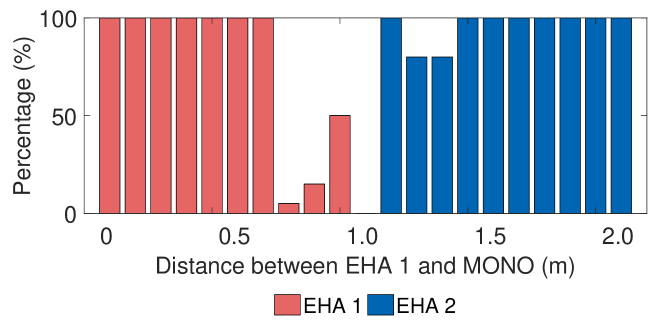
Two EHAs are placed two meters apart and a MONO is placed at 20 measuring points in a straight line between the EHAs. The interval distance of the measuring points is 10 cm. The transmission power of the EHAs is set to 0 dBm. The MONO stays at each measuring point for 30 s and sends beacon-request every second. The two EHAs send their beacon-reply back immediately after receiving the beacon-request.
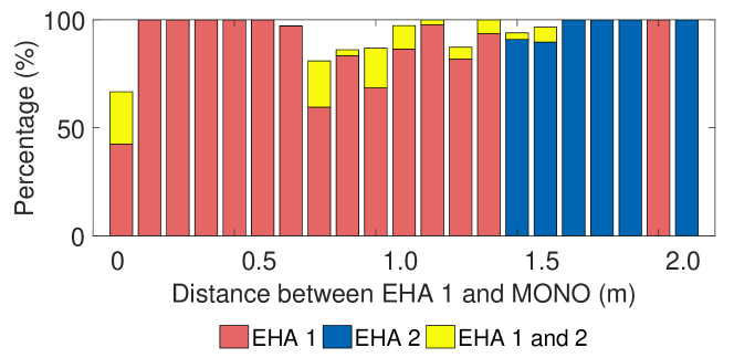
The experiment is first performed without orthogonal codes, and the results are shown in Fig. 5(a). After that, the same experiment is performed with orthogonal codes, and the results are shown in Fig. 5(b). In Fig. 5(a), most of the collision packets can be correctly decoded in capture effect. But there is a “dead zone” between the two EHAs, i.e. an area of no packet reception. This is because the packets collide but the SINR is insufficient to receive a correct packet in this region. Fig. 5(b) shows that the “dead zone” is eliminated using orthogonal codes. Moreover, there is some chance that the MONO decodes the two EHA IDs from one collision beacon.
VI-B Passive Wakeup
The collision based beacon introduced in Sec. VI-A requests synchronization of packet transmission among EHAs. However, the harvested energy is not enough for EHAs to continuously listen to the synchronization signal, i.e. beacon-request. Therefore, we propose passive wakeup approach to wakeup EHAs from sleeping mode only when the beacon-request is sent from MONO.
VI-B1 Basis of Passive Wakeup
The existing BLE beacon devices do not have passive wakeup function. We achieve RF-based passive wakeup by taking advantage of the properties of BLE device, RF energy transmitter and harvester as follows.
-
(i)
The harvested RF energy of EHA is very sensitive to the variation of the Tx power from RF energy transmitter. EHA can detect the ON/OFF state of ESA-Transmitter by measuring the harvested power. Therefore, changing the Tx power from ON to OFF state in the ESA-Transmitter is used as the wakeup signal to EHAs.
-
(ii)
Analog to Digital Converter (ADC) is widely used to measure the voltage level of batteries. ADC of Nordic nRF51822 enables sampling of external signals through a front-end multiplexer. Using the same BLE device as shown in Sec.VI-A2 (Smart Beacon Kit form Nordic Semiconductor with BLE [7]), we measure the power consumption of different operations as shown in Table V. The power consumption of ADC measurement is much lower than transmitting and receiving packets. Moreover, it is of the same magnitude as the harvested power (from 3.2 mW at 1 m to 0.79 mW at 3 m). Although the power consumption of ADC measurement is larger than harvested power at the distance of 3 m, EHA can conduct ADC measurement periodically and be in sleeping mode the rest of time. This ensures that the average power consumption of periodical ADC measurement is lower than the harvested energy. If the ESA is switched off shortly for sending passive wakeup signal, the remaining energy in the capacitor of EHA is enough for its ADC operation. Therefore, we make EHAs periodically wakeup from sleeping mode and perform the measurement of the the harvested energy voltage on ADC port.
-
(iii)
ESAs are deployed with fixed power supply for transmitting wireless energy. Therefore, ESA-Controller, which attaches on ESA-Transmitter, has enough energy to listen to the communication channel continuously. We make ESA-Controller listens to the beacon-request signal from MONO in full time.
| Operation | Power (mW) | Time (ms) | Energy (J) |
| Transmitting | 35.88 | 0.80 | 28.7 |
| Receiving | 20.17 | 0.60 | 12.1 |
| ADC | 1.69 | 0.65 | 1.10 |
| Sleeping | 0.14 |
-
•
Voltage supply is 3 V. The payload length of BLE packet is 30 bytes.
VI-B2 Procedure of Passive Wakeup
Now, we combine the above three properties together to implement passive wakeup.
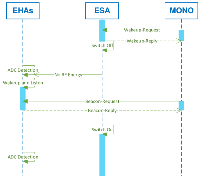
First of all, each EHA makes ADC detection with period . MONO broadcasts a wakeup-request message to ESA. The ESA-Controller sends a wakeup-reply message back immediately after receiving wakeup-request. This wakeup-reply from the ESA is used to notify the MONO that EHAs will be wakeup in listening mode. After sending the wakeup-reply, the ESA sends a passive wake up signal to all the neighbor EHAs by switching off the Tx power of ESA-Transmitter for a short time and then switch on again. Once a voltage falling of the harvested power is measured using ADC detection by a EHA, it wakes up from sleeping mode and starts listening. Meanwhile, the MONO receives the wakeup-reply from the ESA and waits for to broadcast the beacon-request to the EHAs. After receiving the beacon-request from the MONO, the EHAs send beacon-reply back to the MONO. Then the MONO decodes the packet by the collision based beacon approach as explained in Sec. VI-A. In this workflow, each EHA periodically wakes up and conducts ADC measurement to detect passive wakeup signal. To guarantee that all the EHAs can hear the beacon-request signal from the MONO, each EHA wakes up immediately after receiving the passive wakeup signal and listens a maximal period of . If a EHA receives nothing in that time frame, then it sleeps again. The whole process is illustrated in Fig. 6.
VI-B3 Optimization on Passive Wakeup
To further reduce the average power consumption of EHA, we optimize the ADC detection period of EHA.
Suppose MONO requests beacon from EHAs with period . Name the average power consumption of a EHA in as . As explained in Sec.VI-B2, ESA-Transmitter switches OFF as wakeup signal after sending wakeup-reply. Suppose the time length from switching ESA-Transmitter OFF until detecting passive wakeup signal by the EHA is . After receiving wakeup-reply from ESA, the MONO sleeps for and then sends beacon-request. Then the EHA is waken up and stays in receiving state for time length . Denote as the number of ADC measurement during . Name , and as the time spent on ADC measurement, receiving packet, and packet transmission by EHA, respectively. Name , , , and as the power consumption of ADC measurement, packet reception, packet transmission and sleeping by EHA, respectively. We assume the time of detecting passive wakeup signal happens uniformly in the ADC measurement period .
Proposition 1.
The value of producing minimum expected power consumption at EHA is
| (2) |
Proof.
The CDF of is , and the expectation of is . Then the expected receiving state time is . The time of sleeping during is . Then the average power consumption of a EHA in a beacon period is
| (3) |
where . As is discrete value, we replace it with a continuous value for estimating the minimum value . The value of that minimizes the expectation of is calculated as which results in (2). ∎
VI-C Range Estimation
The passive wakeup approach reduces the power consumption of idle listening in EHAs as present in Sec.VI-B. However, there are two problems as follows.
-
(i)
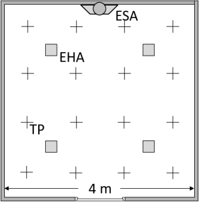
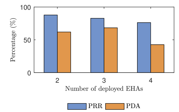
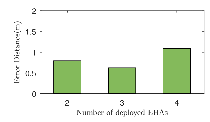
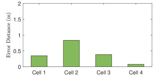
The passive wakeup approach activates all the EHAs near the ESA. As the number of EHAs that send collision based beacon increases, the decoding error in MONO might increase. To prove this assumption, we deploy 2, 3 and 4 EHAs respectively around a ESA, and test the PRR, PDA and LE. The deployment setup and testing positions are illustrated in Fig. 7(a). The test results are shown in Fig. 7(b) and Fig. 7(c). The key result is that the PRR and PDA decrease as the number of EHAs increases. This is mainly caused by the radio interference to the orthogonal code from multiple EHAs. It means that radio interference caused by multiple EHAs limits the performance and scalability of BEH system.
-
(ii)
The aim of BEH is to make MONO receive information, such as node ID, from the nearest EHA. It is more energy efficient to wakeup only the EHAs which are close to the requesting MONO.
Based on the analysis above, we need to restrict the number of EHAs used for beaconing. We propose to use the harvested RF energy of MONO for estimating its possible range. This range information is used to select the EHAs that are near MONO for sending collision based beacon.
VI-C1 Properties of Harvested Power
We take advantage of the power of harvested RF energy to make range estimation for two reasons.
-
(i)
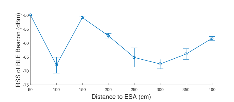
The power of harvested RF energy is more stable than the received signal strength (RSS) of BLE packets at the same distance. As a comparison, we measure the power of harvested RF energy using ADC and the RSS of BLE packets at various distances. At each testing position, we record 100 measurement results. The measurement results are shown in Fig. 8. The RSS of BLE fluctuates much, which is difficult to be used for distance estimation. The power of harvested RF energy is rather stable. Therefore, we take advantage of the attenuation of harvested power over distances to estimate the possible location range of MONO.
-
(ii)
ESA constantly transmits RF energy to the nearby space. Its transmission radio covers the whole deployment area of EHAs. We do not need to deploy any additional communication component for range estimation.
VI-C2 Procedure of Range Estimation
Suppose EHAs are deployed uniformly around the ESA. The ADC based power measurement results of the MONO and EHA are and , respectively. At the beginning of the range estimation process, each EHA reports its power measurement to the ESA. Name the measured power of EHA as .
Although the power of harvested RF energy is more stable than the RSS of BLE beacon packet, it is inaccurate to use it for calculating the precise location of MONO. As explained in Sec.V, ESA is pre-programmed with the position map of EHAs. Therefore, we define a threshold value of to categorize the EHAs into two parts: the EHAs which are closer to the ESA, and the EHAs which are farther to the ESA. To set the value of , we pick the EHA which is at the geographic middle position of the deployed EHAs. Then we set equal to the measured harvested power of the picked EHA.
After comparing the value between and , we name the two sets of EHAs as EHA and EHA. To request beacon services, the MONO broadcasts a beacon-request with . After receiving the beacon-request, the ESA compares with the threshold value . If , the ESA sends the passive wakeup signal and broadcasts a sleep packet with the IDs of the EHAs in . If , the ESA sends the passive wakeup signal and broadcasts a sleep packet with the IDs of the EHAs in . Once woken up, the EHAs listen to the message from the ESA. If the EHA does not receive a sleep command with its ID, it keeps listening to a beacon-request from the MONO, otherwise goes to sleep. The detailed process is presented in Fig. 9.
The accuracy of range estimation using harvested RF power is low, which could cause error in range estimation. Suppose the range estimation of the MONO is wrong, and the BLE radio transmission range of EHA is set to be only inside its cell area. Then the MONO can not receive a beacon-reply from the EHAs. We cope with this error situation as follows. If the MONO does not receive any beacon-reply in a beacon period, the MONO will request the ESA to re-send wakeup signal by wakeup-request packet with “request-again” in the payload. If the ESA sends wakeup signal to the EHAs of previously, it sends wakeup signal to the EHAs in now. If the ESA sends wakeup signal to the EHAs of previously, it sends wakeup signal to the EHAs in now. For the convenience of expression, we name the range of EHAs in the first round of wakeup as , and the second round as .
VI-D Two Wave Beacons
The range estimation approach of Sec.VI-C reduces some unnecessary beacon communication by waking up the EHAs of specified area. However, this approach relies on the measurement of harvested power. The measurement value of and can be affected by environmental factors, including obstacles between devices, relative direction of antennas between energy transmitter and harvester, destructive RF interference from nearby ESAs, etc. Therefore, we propose an approach called two wave beacons to reduce part of unnecessary beacons and increase energy utilization efficiency without extra measurements or range estimation. The two wave beacons approach is based on the two properties of RF energy harvesting as follows.
-
(i)
According to the measurement results as shown in Fig.3(b), the harvested energy by EHAs is quite unbalanced. EHA at 1.0 m to the ESA-Transmitter harvests 36 times more energy than at 3.5 m. Therefore, it is more important to reduce unnecessary beacons and save energy in the EHAs which are further away from ESA.
-
(ii)
According to the collision based beacon in Sec.VI-A, all the EHAs near the MONO must wake up at the same time. This means that, in every round of beacon communication, all the EHAs must wait until the EHA which harvests the lowest power has enough energy. Therefore, it is necessary to increase the energy efficiency of EHAs which are further away from the ESA by shifting some of their workload to the closer EHAs.
VI-D1 Procedure of Two Wave Beacons
The two wave beacons approach includes two rounds, i.e. waves, of beacon communication between MONO, ESA and EHAs. Each wave is similar to the the workflow of Sec.VI-C. The key difference is which EHAs are selected to receive sleep signal.
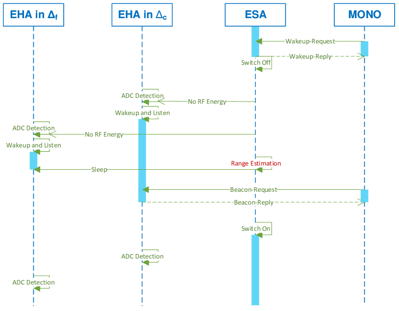
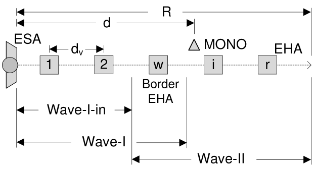
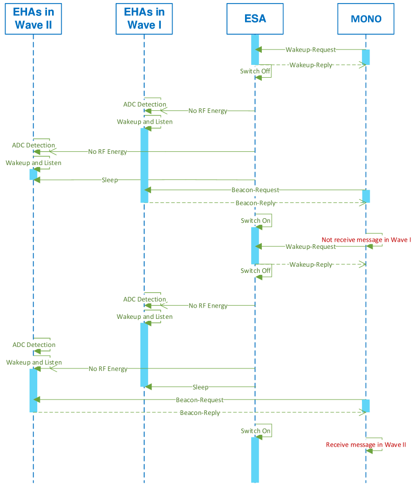
We use Fig.10 as an example of the system setup. The same as Sec.VI-C, EHA measures the mean harvested power and sends this information to the ESA. The ESA selects the harvested power from one of the EHAs as the power threshold . Suppose the harvested power of EHA is selected as the threshold value . We call the EHA as border EHA. We categorize the EHAs into two groups by the border EHA. The first group is the EHAs with , which is called Wave-I. The second group is the EHAs with , which is called Wave-II. To simplify the explanation, we name the area of Wave-I except the cell of border EHA as Wave-I-in. The procedure of two wave beacons is as follow, and its sequential diagram is shown in Fig. 11.
-
(i)
Step I First Wave Beacon: ESA wakes up EHAs in Wave-I to send beacon messages to MONO. In this step, there are two possible conditions.
-
•
Suppose the MONO is in Wave-I-in. The MONO will receive the beacon-reply from one of the EHAs in Wave-I-in. This beacon packet is decoded for its information and counted as the proximity detection result. In the example of Fig. 10, the MONO will receive the beacon from EHA 1 or EHA 2. After that, the procedure of the two wave beacons approach finishes.
-
•
Suppose the MONO is in Wave-II. The border EHA always has the closest distance to the MONO. According to the measurement results of collision based beacon in Sec.VI-A, MONO receives the beacon message from the nearest EHA. So that, the MONO will always decode the beacon packet from the border EHA. In this situation, we cannot confirm the position of the MONO. The MONO initiates the second wave by re-sending wakeup-request packet with “request-again” in the payload.
-
•
-
(ii)
Step II Second Wave Beacon: After the operations of the first wave beacon, we determine that the MONO must be inside the Wave-II, although its position is unclear. In the second wave beacon, ESA wakes up EHAs in Wave-II to send beacon messages to MONO. Then the MONO will receive and decode the beacon-reply from one of the EHAs in Wave-II. This beacon packet is decoded for its information and counted as the proximity detection result. The procedure of the two wave beacons finishes.
VI-D2 Optimization on Two Wave Beacons
Name the time length that all the required EHAs harvest enough energy for a round of beacon operation as charging period (CP). For two wave beacons, the CP of Wave-I equals the charging time of the border EHA, and the CP of Wave-II equals the charging time of the furthest EHA. To understand how two wave beacons improve the energy utilization efficiency, we analyze the tradeoff between CP and PDA in this section. We first analyze two wave beacons in one dimension, and then explain the steps to extend the analysis to two dimensions.
Nodes Deployment
We deploy ESA, MONO, and EHAs in a line. The deployment is shown in Fig. 10. The ESA is located at the beginning of the line. The MONO is randomly and uniformly distributed, such that MONO’s distance from ESA is , and is the maximum separation between ESA and MONO. The EHA which is the closest to the ESA is from the ESA. Each EHA at location is positioned with a regular interval , such that . Then the probability that the MONO is inside a cell is . The position of EHA is . Assume each EHA has its beacon communication range, i.e. from , located at the middle distance between EHA and EHA , to located at the middle distance between EHA and EHA (for : position of ESA). Finally, all EHAs are divided into two groups, denoted as (i) first wave beacon group—with EHA , and (ii) second wave beacon group—with EHA . EHA is a border EHA, which belongs to both groups.
Radio Propagation
Assume the radio propagation follows a pathloss and log-normal shadowing model in which pathloss exponent is denoted as , and log-normal random value . Denote (dB) as the mean received signal strength at distance , where is the EHA transmitted power, is the (known in advance) reference pathloss at a reference distance . The communication signal strength from EHA to MONO is denoted as . Then , where . Assume that is the energy required to perform one round of beacon by EHA. Then is the charging time that the EHA needs to wait until it has enough energy for responding the next round of beacon request. Then .
Beacon Analysis
Based on the above model, we are now ready to introduce the following proposition in one dimension of EHAs. For two dimensional area, the analysis is the same except two points. Firstly, replace the spatial distribution of MONO in the two dimensional area. Secondly, change the border EHA from one node to the set of border EHAs.
Proposition 2.
The approach of two wave beacons sacrifices proximity detection accuracy of MONO for decreasing charging period of EHAs.
Proof.
Denote as the event that MONO is in cell and the proximity detection results is in cell . Suppose we only consider the capture effect in collision based beacon, with all EHAs involved, the correct probability to decode beacon is calculated as
| (4) |
To simplify the calculation of (4) we use . From (4), the expected probability that MONO is inside the correct cell is .
Now, if the first wave beacon group of the EHAs is used, following the same analysis process, the event that MONO is in cell while it is detected in cell is . The expected probability that MONO is inside cell and it is detected in cell is .
If all EHAs are woken up at the same time to beacon, then the expectation value of PDA and CP are
| (5) |
| (6) |
If the two wave beacons is used, then the expectation value of PDA and CP are
| (7) |
| (8) |
Due to the exponential decay of RF signal, we have . Based on the above equations, it is easy to see that and , which concludes the proof. ∎
ESA:
EHA:
MONO:
ESA:
EHA:
MONO:
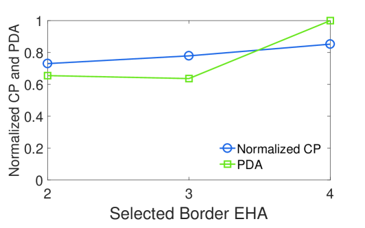
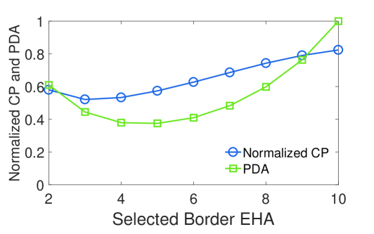
We confirm this conclusion by the calculation of 4 EHAs and 10 EHAs respectively. The calculation results are shown in Fig. 12. If the border EHA ID equals the total number of EHAs (border EHA = 4 in Fig.12(a), border EHA = 10 in Fig.12(b)), we do not use two wave beacons but wake up all EHAs at once. Compared with the approach to wakeup all EHAs, two wave beacons approach loses some accuracy, however its average charging period decreases. We find that there is the minimum PDA, where border EHA = 3 in Fig.12(a) and border EHA = 5 in Fig.12(b). We should avoid selecting these border EHA while using the two wave beacons approach. We further verify the above conclusion using the real hardware experiments in Sec. VIII.
VII System Implementation
In this section, we explain the implementation of software and hardware based on the components of Sec.VI.
VII-A Software Implementation
The main beacon packets in BEH are beacon-request, beacon-reply, wakeup-request, wakeup-reply, and sleep. All these packets have a fixed payload length of 30 bytes. The beacon-request and wakeup-request packets have the same format. They contain the ID of MONO in the first two bytes of the payload. The beacon-reply and wakeup-reply packets have the same format. They contains the EHA ID encoded by the FEC which is then encoded by the orthogonal codes in the payload. For comparison, we present the program flow using range estimation (Sec.VI-C) and two wave beacons (Sec.VI-D) in Algorithm 1 and Algorithm 2 respectively.
VII-B Hardware Implementation
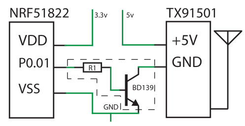
Three types of hardware devices are implemented, including ESA, EHA, and MONO. The electrical connections of the three nodes are given in Fig. 13.
VII-B1 ESA
ESA consists of two parts ESA-Transmitter and ESA-Controller. ESA-Transmitter is Powercast TX91501 Powercaster transmitter [8], which has an EIRP of 3 W and operates at a center frequency of 915 MHz. ESA-Controller is the nRF51822 SoC Smart Beacon Kit [42] with integrated PCB antenna, which is connected with ESA-Transmitter. A transistor is added to the power line of the ESA-Transmitter, so that the nRF51822 can switch the power of ESA-Transmitter on or off. ESA-Controller transmission power is 4 dBm. The schematic of ESA is shown in Fig. 13(a). The ESA has a fixed power supply. Therefore ESA-Controller listens all the time to the communication channel.
When a high voltage signal is given to the transistor, ESA-Transmitter is turned on and starts transmitting energy. After receiving a wakeup-request signal, ESA-Controller controls ESA-Transmitter to send a passive wakeup signal. The nRF51822 mote of ESA-Controller pulls the transistor low to turn off the ESA-Transmitter, after which it pulls the transistor high to turn on the ESA-Transmitter again. By this way all the nearby EHAs will detect the passive wakeup signal.
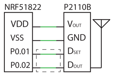
VII-B2 EHA
The Powercast P2110B power harverster [8] is used for harvesting power for the nRF51822 BLE mote. The harvester antenna is a vertical polarized patch antenna with a 6.1 dBi gain. The version of development board for the nRF51822 is the Smart Beacon Kit. To keep the power consumption at a minimum, the transmission power of EHA is set to -20 dBm, and all the peripherals of the BLE mote are turned off except for one hardware timer which is set to generate an interrupt periodically. The CPU is most of the time in wait for interrupt state, which we denote as the sleep state.
The schematic of EHA is shown in Fig.13(b). As EHA is battery-less, the nRF51822 chip receives power from the pin of the harvester. The other connections are used for the passive wakeup and implemented as follows. The and pins are used for obtaining the received signal strength indication (RSSI). The and the are connected to P0.01 and P0.02 of the nRF51822, respectively. When is pulled high, represents the RSSI of the harvester. When the voltage is lower than the threshold , the nRF51822 is woken up and starts listening to incoming radio packets until a valid packet is received. When a timeout is reached, the nRF51822 goes back to sleep.
VII-B3 MONO
Compared with the hardware and connections of EHA, we only change the type of BLE board in MONO to increase the signal sensitivity. The BLE development board of MONO is nRF51822 nRFgo PCA10005 [36]: an ARM Cortex M0 CPU with a helical monopole SMA-connected antenna. The transmission power is 4 dBm. The schematic of MONO is given in Fig. 13(b).
VIII Experimental Results
We evaluate the performance of BEH from the following aspects. Firstly, we test whether the basic functions of BEH, including BLE beacon and passive wakeup, can work properly using harvested RF energy (Sec.VIII-A). Secondly, we test the performance of collision based beacon in an indoor area (Sec.VIII-B). Thirdly, we test BEH with increased deployment density of EHAs. In this test, the components including collision based beacon, passive wakeup, and range estimation. The operations of EHA and MONO completely rely on harvest RF energy (Sec.VIII-C). Finally, we test BEH using two wave beacons (Sec.VIII-D), compared with the third experiment using range estimation.
VIII-A Simple Beacon with Passive Wakeup
To evaluate the performance of BEH, it is necessary to know whether the implemented BEH system is able to harvest enough energy for beacon communication from the RF energy transmitter. To achieve this aim, we measure the time length that EHA needs to harvest RF energy for operating a beacon communication. In this experiment, we only test the basic beacon operation and passive wakeup with RF energy harvesting. There is not collision based beacon as in Sec.VI-A, optimized for minimizing average power consumption as in Sec.VI-B3, range estimation as in Sec.VI-C, or two wave beacons as in Sec.VI-D.
VIII-A1 Experiment Setup
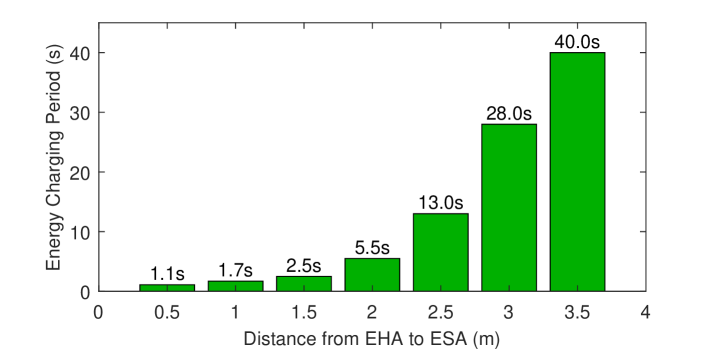
One EHA is used to send beacon messages. The test distance between ESA and EHA is from 0.5 m to 3.5 m with interval of 0.5 m. A modified MONO is used in this test. The modified MONO connects to a personal computer, i.e. the harvester is removed while all the power is supported by the USB port of the PC. This modification is needed to keep the MONO in full-time listening mode. The EHA, ESA, and MONO are deployed in the communication range of each other.
At each testing position, the MONO performs 100 wakeup-request with a fixed request period. This particular period is chosen starting at 500 ms and increased with a step of 100 ms. The EHA is activated by passive wakeup signal of ESA from sleeping mode. The EHA sends a beacon-reply immediately after receiving the beacon-request. The beacon-reply packets from the EHA are captured by the modified MONO. We measure the PRR. If the PRR is more than 95%, we assume that the current energy charging period is long enough for the EHA to finish a round of beacon operation at this particular distance.
VIII-A2 Experiment Results
The result of this experiment is presented in Fig. 14. As expected the energy charging period increases as the distance increases. BEH allows perpetual batteryless beacon using RF based energy harvesting, reaching beacon period of 40 s at a 3.5m distance between ESA and EHA. Further we infer that if one needs multiple EHAs to work with the same period, all EHAs need to wait as long as the charging period for the EHA that has the longest distance from ESA. Therefore, the beacon response rate is low bounded by the furthest-located EHA.
VIII-B Collision based Beacon
In this experiment, we aim to evaluate the collision based beacon of Sec.VI-A in rooms. Therefore, we simplify workflow of BEH to focus on collision beacons as follows. The ESA-Transmitter is used for transmitting RF energy for the MONO. The passive wakeup in ESA-Controller is not used. We remove the RF harvester of EHA and connect to a wired power supply, so that the EHA listens the communication channel in full time. If a beacon-request packet is received, the EHA broadcasts beacon-reply. The MONO harvest RF energy as the power supply for beacon communication. It periodically wakes up from sleep to broadcasts beacon-request, and then its radio immediately switches to receiving mode. If a beacon-reply packet is received, it decode the message. After that, the MONO goes back to sleep mode.
VIII-B1 Experiment Setup
| Position of EHAs | PRR (%) | PDA (%) | LE (m) |
|---|---|---|---|
| Room 1 and 2 | 95.5 | 99.3 | 0.03 |
| Room 1, 2 and Corridor | 84.7 | 89.6 | 0.25 |
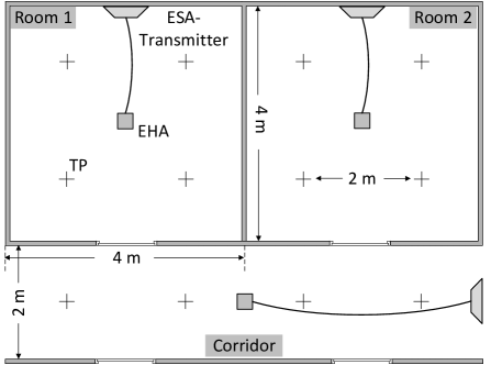
The deployment of ESA, EHA and MONO is shown in Fig.15. The room and corridor are divided into four cells of 2 m2 m respectively. The center of each cell is the test position of the MONO. Three EHAs are deployed with wired power supply from ESA-Transmitter in the center of room 1, room 2 and corridor respectively. The MONO is placed at every testing position. Every device is placed 1.0 m above the floor and they are all in line-of-sight from each other.
The MONO needs to consume extra energy for aggregating the testing results. As the MONO is powered wirelessly, consuming power for result data aggregation will negatively affect the performance of BEH. We overcome this problem by using a BLE USB dongle as a sniffer [7]. This sniffer is deployed near the testing area, and it monitors all the packets sent by the MONO. In our experiment, the result of every beacon round is attached in the beacon-request packet of the next beacon round. The sniffer receives the data and saves it for further data processing.
VIII-B2 Experiment Results
In the first round of experiment, we only deploy two EHAs in the room 1 and 2. In the second round of experiment, we deploy all the three EHAs in the rooms and corridor. At every test position, 50 beacon rounds were performed. For each test position, PRR, PDA and LE are computed and averaged. The results are shown in Table VI. We observe that the PRR and PDA decrease as the number of deployed EHAs increases. This is mostly due the fact of multiple packets collision. In this experiment, we demonstrate two performance of BEH. Firstly, we achieve batteryless MONO based on harvested RF energy. Secondly, the collision based beacon can achieve expected PRR and PDA, if we limit the number of EHAs involved.
VIII-C BEH using Range Estimation in Cell Level EHAs
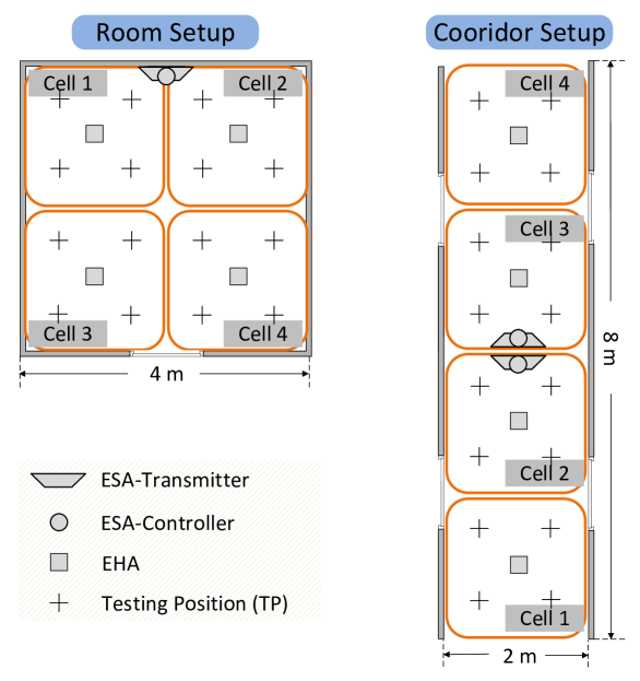
In this experiment, we evaluate the performance of BEH in cell-level of a real office area. We select the range estimation component, instead of the two wave beacons. The BEH system is implemented under Alg.1. The deployment of EHAs, ESAs and the testing positions of MONO are illustrated in Fig. 16.
VIII-C1 Experiment Setup
The experiments are performed in a room and a corridor respectively. Four EHAs are deployed in each scenario. As the length of the corridor is longer than the effective energy transmitting range from ESA to EHA, we deploy two ESAs back-to-back in the middle of the corridor pointing to the begin and the end of the corridor, respectively. Each ESA in the corridor is responsible for waking up and controlling two EHAs. We use the pre-measured harvested power value dBm at the geographic middle position of the deployment area of EHAs as the threshold value to categorize the two ranges. The MONO sends 20 beacon requests at each testing position. The same as in Sec.VIII-B, an BLE packet sniffer was used for result data collection. The decoding for beacon packet is done by the MONO, so only the decoding result is transmitted to the sniffer.
VIII-C2 Experiment Results
| Location | PRR (%) | PDA (%) | LE (m) |
|---|---|---|---|
| Room | 97.5 | 59.9 | 0.85 |
| Corridor | 100 | 82.2 | 0.41 |
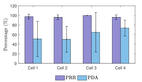
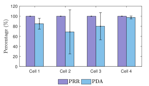
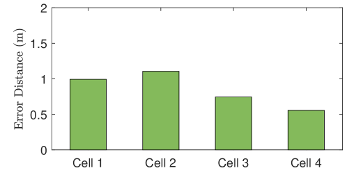
The average experiment results in the room and corridor are shown in Table VII, and the results in each cell are shown in Fig.17. Compared with the BEH room-level experiment results as shown in Table VI, the average PRR increases. This is because of the range estimation component, which selects only part of the EHAs to send beacon signals in a beacon round. The cell-level accuracy of BEH is lower than the room-level accuracy. We find that the cell-level accuracy at some cell positions is much lower than the others as shown in Fig.17. This is due to two reasons:
-
(i)
The deployed cell area of each EHA is only 4 in this experiment, which is much smaller than the 16 deployed room area in Sec.VIII-B. The received beacon packets from EHAs by the MONO only have small difference in RSS. This could cause error for decoding the packet from the closest EHA.
-
(ii)
The radio pattern of ESA-Transmitter has only 60∘ coverage in width and height, therefore some testing positions at the border of the room are not effectively covered. The MONO at these positions can not harvest enough energy and work properly.
The test results prove that BEH is able to achieve cell-level beacon using harvested RF energy. The PRR is high enough for real applications. The PDA is low in some scenarios, which requires further improvement.
VIII-D BEH using Two Wave Beacons in Cell Level EHAs
In this experiment, we evaluate the performance of BEH with two wave beacons component and validate that the two wave beacons mechanism improves beacon rate of EHAs. We implement the BEH system using Alg.2.
VIII-D1 Experiment Setup
We set up one ESA and four EHAs in a corridor, as depicted in Fig. 18. Compared with the experiment in Sec.VIII-C, we deploy EHAs closer to each other. The first EHA is located at a 50 cm distance from the ESA while the remaining three EHAs are positioned at a 1 m distance from the previous EHA on a straight line. The MONO is located first at the same position as the ESA and moved away from it in steps of 50 cm until a 4 m distance is reached. At each MONO’s testing position 20 beacon events are performed. The procedure of packet decoding and results aggregation is the same as in Sec.VIII-B and Sec.VIII-C. Three types of scenarios are tested for comparison:
-
1.
EHA 2: two wave beacons approach is enabled with border EHA 2.
-
2.
EHA 3: two wave beacons approach is enabled with border EHA 3.
-
3.
Wake all: two wave beacons approach is disabled and all EHAs broadcast beacon-reply after receiving beacon-request.
VIII-D2 Experiment Results
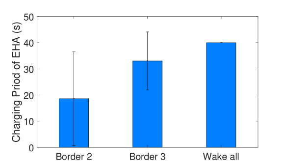
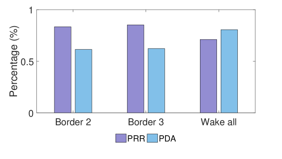
The charging period of the EHAs is defined and analyzed in Sec.VI-D2. The approach to measure the energy charging period of each EHA is the same as in Sec.VIII-A. The experiment results on energy charging period of two wave beacons are shown in Fig. 19(a). Compared with the case when all EHAs are woken up, the testing results with two wave beacons have smaller charging period. The average charging period with border EHA 2 is around 47% of “wake all” scenario. These results validate that the charging period of EHAs can be reduced by two wave beacons approach. While decreasing the energy charging period, the experiment results in Fig.19(b) illustrate the increasing of PRR and decreasing of PDA. The tradeoff between charging period and PDA aligns with the analysis results shown in Sec VI-D2. Compared with the two wave beacons, the PRR in the scenario of “wake all” is lower. The main reason is that there are more collisions between the packets of EHAs in the scenario of “wake all”. Therefore, the probability that packets are corrupted increases. Meanwhile, compared with the scenario of “wake all”, the accuracy of two wave beacons decreases. We analyze the testing results and find the following reason. In the first wave of beacons, while the MONO is outside the area of Wave-I, the MONO can not always receive and decode the ID of the border EHA. This error causes that the second wave of beacons can not be activated.
Overall we conclude that two wave beacons approach is able to decrease the average energy charging period of EHAs and increase the PRR, while sacrificing some PDA.

IX Future Work
Based on our experiment results, we conclude that the harvested RF energy is able to support beacon based applications in batteryless BLE devices. Meanwhile there exists some points worth of further improvement.
-
1.
BEH does not consider the situations that affect the harvested RF power, such as obstacles between ESA, EHA and MONO. The system design assumes the devices are deployed in line-of-sight of each other. It is unknown how EHAs should be categorized into two groups by range estimation approach or by two wave beacons approach, if the harvested energy of EHAs are affected by nearby obstacles. We need an approach to cope with complicated energy radio environment.
-
2.
The performance of BEH is unknown if multiple ESAs are deployed. Firstly, the destructive radio from multiple RF energy transmitters will decrease the harvested energy of EHAs and MONOs. Secondly, the passive wakeup signal from multiple ESAs will trigger unnecessary wakeup of EHAs. To eliminate these effects, we need an approach to coordinate the operation of ESAs.
-
3.
The scalability of collision based beacon in BEH is unknown. Firstly, we only test the beacon communication with maximum 4 EHAs. The testing results show that the PRR and PDA decrease as the number of EHA increases. This means that collision based beacon approach should be further improved to cope with multiple beacon messages. A possible solution is using more efficient encoding and decoding process to reduce interference. Secondly, MONO needs to try all the orthogonal codes to decode the beacon message, which is energy-consuming. As the number of EHA increases, the power consumption on decoding the orthogonal codes will become unbearable. We need a strategy to shrink the list of orthogonal codes. A possible solution is to divide the EHA network into sub-areas. Instead of having an unique orthogonal code in the whole network, each EHA has a pre-defined unique orthogonal code in each sub-area. Once a MONO is inside a sub-area, a ESA sends the set of orthogonal codes of the sub-area to the MONO.
X Conclusion
In this paper we presented a RF energy harvesting-enabled indoor BLE beacon system named as BEH. The key innovations of BEH are the four components to align the energy requirement of BLE communication to the limited budget of harvested energy, including: (i) leveraging collisions based beacon to extremely decrease energy used for receiving; (ii) using normal RF energy transmitting device to build a passive wakeup function, which is used for decreasing the power consumption on idle listening; (iii) waking up only the EHAs near the MONO to send beacon messages by estimating the general range of the MONO; (iv) using two rounds (waves) of beacon to shift some workload from the EHAs harvesting less energy to the ones harvesting more energy. We implement BEH with these components using off-the-shelf BLE motes and RF harvesting devices. Based on the extensive indoor experiments, we show that BEH is capable of providing continuous beacon services to mobile nodes based on limited harvested energy from dedicated RF transmitter. To the best of our knowledge, BEH is the first indoor BLE beacon system powered by RF energy transmission.
References
- [1] Y. Zhuang, J. Yang, Y. Li, L. Qi, and N. El-Sheimy, “Smartphone-based indoor localization with bluetooth low energy beacons,” Sensors, vol. 16, no. 5, p. 596, 2016.
- [2] R. Faragher and R. Harle, “An analysis of the accuracy of bluetooth low energy for indoor positioning applications,” in Proceedings of the 27th International Technical Meeting of the Satellite Division of the Institute of Navigation. ION, 2014, pp. 201–210.
- [3] S. A. Cheraghi, V. Namboodiri, and L. Walker, “Guidebeacon: Beacon-based indoor wayfinding for the blind, visually impaired, and disoriented,” in International Conference on Pervasive Computing and Communications. IEEE, 2017, pp. 121–130.
- [4] M. Collotta and G. Pau, “A novel energy management approach for smart homes using bluetooth low energy,” IEEE Journal on Selected Areas in Communications, vol. 33, no. 12, pp. 2988–2996, 2015.
- [5] L. Xie, Y. Shi, Y. T. Hou, and W. Lou, “Wireless power transfer and applications to sensor networks,” IEEE Wireless Commun., vol. 20, no. 9, pp. 140–145, Aug. 2013.
- [6] L. Xiao, P. Wang, D. Niyato, D. Kim, and Z. Han, “Wireless networks with rf energy harvesting: A contemporary survey,” IEEE Commun. Surveys Tuts., vol. 17, no. 2, pp. 757–789, Nov. 2014.
- [7] Nordic Semiconductor, “Bluetooth low energy products,” 2015. [Online]. Available: https://www.nordicsemi.com/eng/Products/Bluetooth-Smart-Bluetooth-low-energy
- [8] Powercast Corp., “Power harvesters and receivers,” 2015. [Online]. Available: http://www.powercastco.com/products/powerharvester-receivers
- [9] H. Jabbar, Y. S. Song, and T. T. Jeong, “Rf energy harvesting system and circuits for charging of mobile devices,” IEEE Transactions on Consumer Electronics, vol. 56, no. 1, pp. 247–253, 2010.
- [10] Q. Liu, K. S. Yildirim, P. Pawełczak, and M. Warnier, “Safe and secure wireless power transfer networks: Challenges and opportunities in rf-based systems,” IEEE Communications Magazine, vol. 54, no. 9, pp. 74–79, 2016.
- [11] P. Kamalinejad, C. Mahapatra, Z. Sheng, S. Mirabbasi, V. C. Leung, and Y. L. Guan, “Wireless energy harvesting for the internet of things,” IEEE Communications Magazine, vol. 53, no. 6, pp. 102–108, 2015.
- [12] V. Raghunathan, A. Kansal, J. Hsu, J. Friedman, and M. Srivastava, “Design considerations for solar energy harvesting wireless embedded systems,” in Proceedings of the 4th international symposium on Information processing in sensor networks. IEEE, 2005, p. 64.
- [13] A. Kansal, J. Hsu, S. Zahedi, and M. B. Srivastava, “Power management in energy harvesting sensor networks,” ACM Transactions on Embedded Computing Systems, vol. 6, no. 4, p. 32, 2007.
- [14] S. P. Beeby, M. J. Tudor, and N. M. White, “Energy harvesting vibration sources for microsystems applications,” Measurement science and technology, vol. 17, no. 12, p. R175, 2006.
- [15] Q. Liu, M. Golinński, P. Pawełczak, and M. Warnier, “Green wireless power transfer networks,” IEEE Journal on Selected Areas in Communications, vol. 34, no. 5, pp. 1740–1756, 2016.
- [16] A. Kurs, A. Karalis, R. Moffatt, J. D. Joannopoulos, P. Fisher, and M. Soljačić, “Wireless power transfer via strongly coupled magnetic resonances,” Science, vol. 317, no. 5834, pp. 83–86, 2007.
- [17] uBeam, “ubeam wireless power,” 2014. [Online]. Available: http://www.ubeam.com
- [18] H. Ju and R. Zhang, “User cooperation in wireless powered communication networks,” in Global Communications Conference. IEEE, 2014, pp. 1430–1435.
- [19] Y. Peng, Z. Li, W. Zhang, and D. Qiao, “Prolonging sensor network lifetime through wireless charging,” in Real-Time Systems Symposium. IEEE, 2010, pp. 129–139.
- [20] I. in’t Veen, Q. Liu, P. Pawelczak, A. Parks, and J. R. Smith, “Blisp: Enhancing backscatter radio with active radio for computational rfids,” in International Conference on RFID. IEEE, 2016, pp. 1–4.
- [21] J. Park and B. Clerckx, “Joint wireless information and energy transfer with reduced feedback in mimo interference channels,” IEEE Journal on Selected Areas in Communications, vol. 33, no. 8, pp. 1563–1577, 2015.
- [22] K. E. Jeon, J. She, P. Soonsawad, and P. C. Ng, “Ble beacons for internet of things applications: Survey, challenges, and opportunities,” IEEE Internet of Things Journal, vol. 5, no. 2, pp. 811–828, 2018.
- [23] A. Nasiri, S. A. Zabalawi, and G. Mandic, “Indoor power harvesting using photovoltaic cells for low-power applications,” IEEE Transactions on Industrial Electronics, vol. 56, no. 11, pp. 4502–4509, 2009.
- [24] W. S. Wang, T. O’Donnell, N. Wang, M. Hayes, B. O’Flynn, and C. O’Mathuna, “Design considerations of sub-mw indoor light energy harvesting for wireless sensor systems,” ACM Journal on Emerging Technologies in Computing Systems, vol. 6, no. 2, p. 6, 2010.
- [25] W.-C. Shih, P. H. Chou, and W.-T. Chen, “A batteryless beacon based on dual ism-band rf harvesting with solar-biasing current,” in Proceedings of the 4th International Workshop on Energy Harvesting and Energy-Neutral Sensing Systems. ACM, 2016, pp. 7–12.
- [26] L. M. Ni, D. Zhang, and M. R. Souryal, “RFID-based localization and tracking technologies,” IEEE Wireless Commun., vol. 18, no. 2, pp. 45–51, Apr. 2011.
- [27] W. Zhu, J. Cao, Y. Xu, L. Yang, and J. Kong, “Fault-tolerant rfid reader localization based on passive rfid tags,” IEEE Trans. Parallel Distrib. Syst., vol. 25, no. 8, pp. 2065–2076, Aug. 2014.
- [28] S. S. Saab and Z. S. Nakad, “A standalone RFID indoor positioning system using passive tags,” IEEE Trans. Ind. Electron., vol. 58, no. 5, pp. 1961–1970, Jul. 2011.
- [29] L. Yang, Y. Chen, X.-Y. Li, C. Xiao, M. Li, and Y. Liu, “Tagoram: Real-time tracking of mobile rfid tags to high precision using COTS devices,” in Proc. ACM MobiCom, Hawaii, USA, Sep. 7–11 2014.
- [30] L. M. Ni, Y. Liu, Y. C. Lau, and A. P. Patil, “LANDMARC: indoor location sensing using active RFID,” Springer Wireless Networks, vol. 10, no. 6, pp. 701–710, Nov. 2004.
- [31] Y. Liu, Y. Zhao, L. Chen, J. Pei, and J. Han, “Mining frequent trajectory patterns for activity monitoring using radio frequency tag arrays,” IEEE Trans. Parallel Distrib. Syst., vol. 23, no. 11, pp. 2138–2149, Dec. 2011.
- [32] D. J. Yeager, P. S. Powledge, R. Prasad, D. Wetherall, and J. R. Smith, “Wirelessly-charged uhf tags for sensor data collection,” in 2008 IEEE International Conference on RFID, April 2008, pp. 320–327.
- [33] M. Philipose, J. R. Smith, B. Jiang, A. Mamishev, S. Roy, and K. Sundara-Rajan, “Battery-free wireless identification and sensing,” IEEE Pervasive Computing, vol. 4, no. 1, pp. 37–45, Jan 2005.
- [34] A. P. Sample, D. J. Yeager, P. S. Powledge, A. V. Mamishev, and J. R. Smith, “Design of an rfid-based battery-free programmable sensing platform,” IEEE Transactions on Instrumentation and Measurement, vol. 57, no. 11, pp. 2608–2615, Nov 2008.
- [35] P. Zhang, J. Gummeson, and D. Ganesan, “Blink: A high throughput link layer for backscatter communication,” in Proceedings of the 10th international conference on Mobile systems, applications, and services. ACM, 2012, pp. 99–112.
- [36] Nordic Semiconductor, “nRF51822 nRFgo development kit,” 2015. [Online]. Available: https://www.nordicsemi.com/eng/Products/Bluetooth-Smart-Bluetooth-low-energy/nRF51822-Development-Kit
- [37] M. Solutions, “Monsoon power monitor,” 2015. [Online]. Available: https://www.nordicsemi.com/eng/Products/Bluetooth-Smart-Bluetooth-low-energy
- [38] Powercast Corp., “Evaluation board for p2110 powerharvester receiver,” 2015. [Online]. Available: http://www.powercastco.com/PDF/P2110-EVB.pdf
- [39] J. C. Arnbak and W. van Blitterswijk, “Capacity of slotted aloha in rayleigh-fading channels,” IEEE J. Sel. Areas Commun., vol. 5, no. 2, pp. 261–269, Feb. 1987.
- [40] J. van Velzen and M. Zuniga, “Let’s collide to localize: Achieving indoor localization with packet collisions,” in Proc. IEEE PerCom Workshop, San Diego, CA, USA, Mar. 18–22 2013.
- [41] J. E. MacDonald, “Design methods for maximum minimum-distance error correcting codes,” IBM Journal of Research and Development, vol. 4, no. 1, pp. 43–57, Jan. 1960.
- [42] Nordic Semiconductor, “nRF bluetooth smart beacon kit product brief,” 2015. [Online]. Available: http://www.nordicsemi.com/eng/nordic/download_resource/38347/3/57260106