Additive manufactured isotropic NdFeB magnets by stereolithography, fused filament fabrication, and selective laser sintering
Abstract
Magnetic isotropic NdFeB powder is processed by the following additive manufacturing methods: (i) stereolithography (SLA), (ii) fused filament fabrication (FFF), and (iii) selective laser sintering (SLS). For the first time, a stereolithography based method is used to 3D print hard magnetic materials. FFF and SLA use a polymer matrix material as binder, SLS sinters the powder directly. All methods use the same hard magnetic NdFeB powder material. Complex magnets with small feature sizes in a superior surface quality can be printed with SLA. The magnetic properties for the processed samples are investigated and compared. SLA can print magnets with a remanence of mT and a coercivity of T. A complex magnetic design for speed wheel sensing applications is presented and printed with all methods.
keywords:
Magnets , Photopolymerization , Powder Bed Fusion , Material Extrusion, NdFeB1 Introduction
Additive manufacturing (AM) offers a new era of possibilities for magnetic materials and advanced magnetic sensing applications. AM methods creating solid structures layer-by-layer from a formless or form-neutral feedstock by means of chemical or thermal processes. This leads to several advantages like: design freedom, net shape capabilities, waste reduction, minimum lead times for prototyping, compared to traditional manufacturing methods like sintering of full-dense magnets or injection-molding of polymer-bonded magnets.
Fused filament fabrication (FFF) or fused deposition modeling (FDM) is a well-known and widely used AM method to print thermoplastic materials. It uses a wire-shaped thermoplastic filament as building material. The filament is feed to a movable extruder where it heated up above its softening point. The molten material is pressed out of the extruder nozzle and builds the structure layer-by-layer on the already printed and solidified layer [1]. A sketch of the FFF method is shown in Fig. 1(a). By mixing magnetic soft- or hard magnetic materials into the thermoplastic binder, FFF can be also used to 3D print polymer-bonded magnets with filling ratios up to wt.%. [2, 3, 4, 5, 6, 7, 8, 9]. A big disadvantage of polymer-bonded permanent magnets is their lowered maximum energy product compared to sintered magnets due to their plastic matrix material.
To maximize the performance of permanent magnets, the must be increased. Powder bed fusion (PBF) processes does not need a matrix material. It completely melts the metallic powder by the aid of a high-power laser or electron beam source [10]. To optimize the printing process and the quality of the prints, powders with a spherical morphology are preferred [11]. Fig. 1(b) shows a sketch of the printing process. This means theoretically, that fully dense magnets can be printed. However, the rapid liquefaction and cooling rates of the material at the localized heat source, influences the microstructure (size of the grains and the composition of the grain boundaries), and therefore the magnetic properties of the printed structures [12, 13, 14]. The optimization of the magnetic properties of PBF processed magnets is an active research field. The PBF process can be divided into the heating source. Following commonly used PBF printing techniques are used to investigate the capability to print hard or soft magnets: electron beam melting (EBM) [15], selective laser melting (SLM) [16, 17, 18, 19, 20, 21], and selective laser sintering (SLS). SLS does not completely melt each powder layer but sinter the particles to retain their original microstructure. As a second step, the coercivity of the SLS printed samples can be substantially increased by a grain boundary infiltration method [22].
Stereolithography (SLA) was the first commercially available AM technology. The layers of the sliced computer model is scanned by a visible or ultraviolet (UV) light to cure the photosensitive resin selectively for each cross-section, or a digital light processing (DLP) engine projects and cure the whole image of every layer. After each finished layer, the workpiece is lowered by one-layer thickness. Then, the resin sweeps across the cross-section of the partly finished object, and coating it with a new layer of fresh resin. This layer is scanned and cured-on the previous hardened layer. Fig. 1(c) shows the principle of SLA. SLA of soft magnetic materials with a very low filler content of only wt.% is described in [23]. Up to now, no publication about SLA of hard magnetic materials exists.
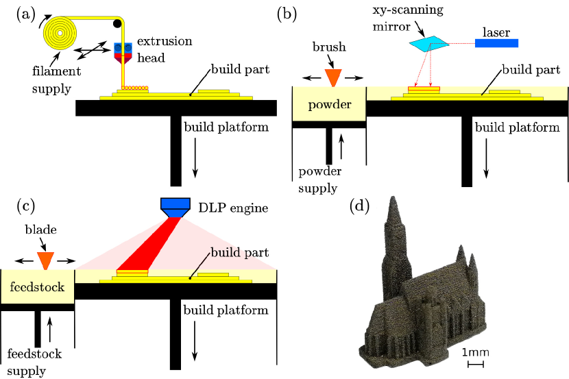
This publication deals with SLA of magnetic isotropic powder in a photo reactive resin. The resolution and quality of the 3D printed permanent magnetic samples are superior. Fig. 1(d) shows a 3D printed magnetic St. Stephen’s Cathedral, Vienna with a minimum feature size of the model of mm and a layer height of µm. Furthermore, the same magnetic isotropic powder is used to print polymer-bonded magnets with FFF and sintered magnets with SLS. All advantages and disadvantages of each method are discussed in detail. Complex magnets are printed and their magnetic properties are investigated and compared.
2 Materials & Methods
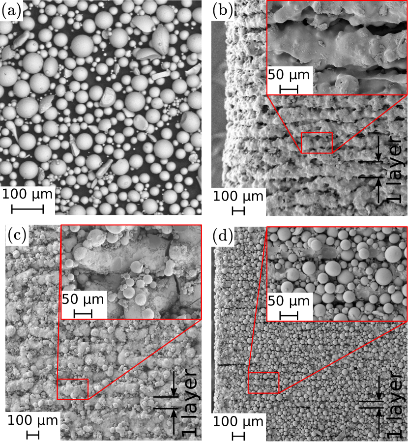
We are using a commercial isotropic NdFeB powder (MQP-S-11-9 supplied by Magnequench Corporation) for all three presented AM methods. This powder has a spherical morphology with a powder size distribution of d50 of µm and the tap density exhibits % of the materials full density. A scanning electron microscopy (SEM) image of the powder can be seen in Fig. 2(a). Its main field of application is the manufacturing of bonded magnets, particularly by injection molding or extrusion. The powder particles have nano-sized NdFeB grains, it have a uniaxial magnetocrystalline anisotropy which are random orientated. This leads to magnetic isotropic behavior of the bulk magnet. This powder is produced by a gas atomization process and a followed heat treatment. The chemical composition states Nd7.5Pr0.7Fe75.4Co2.5B8.8Zr2.6Ti2.5 (at.%) [20].
For the FFF of bonded magnets, a conventional end-user 3D printer Builder from Code P is used. We are using a prefabricated compound (Neofer ® 25/60p) from Magnetfabrik Bonn GmbH. It consists of wt.% MQP-S powder inside a PA11 matrix. To get the wire-shaped filaments for the 3D printer extruder, the Neofer ® 25/60p compound granules are extruded at the University of Leoben with a Leistritz ZSE 18 HPe-48D twin-screw extruder. The extrusion temperature is ∘C, and the hot filament is hauled off and cooled by a cooled conveyor belt. The diameter of mm and tolerances of the filament are controlled by a Sikora Laser Series 2000 diameter-measuring system. The Builder 3D printer can build structures with a maximum size of mm3 (LWH). The layer height resolution can be varied between and mm. Printing speed ranges from to mm/s, traveling speed ranges from to mm/s. To avoid clogging of the nozzle due to the height filler content, the minimum nozzle size diameter is mm. This large nozzle diameter defines the minimum feature size of the prints. The printing temperature for the PA11 compound is ∘C. For a better adhesion of the first layer, the printing bed is heated up to ∘C.
For sample fabrication with the SLS system, a commercial Farsoon FS121M LPBF-machine is used. It is equipped with a continuous wave W Yb-fibre laser with a wavelength of µm and a spot size of mm. It has a build space of mm3 (LWH). The printing of the MQP-S powder is performed under Ar atmosphere with oxygen content below %. A layer thickness of µm, and the powder recoating was done with a carbon fiber brush. All specimens were printed without support structures directly onto a steel substrate plate to ensure proper heat dissipation. The laser power is varied between W and W, and the scan speed is varied between mm/s and mm/s to find the optimal printing parameters. The line energy is a convenient printing parameter. For sintering of the MQP-S powder, line energies between J/mm and J/mm at W, and a hatch spacing of mm is practicable.
Incus GmbH developed an industrial vat photopolymerisation process called Lithography-based Metal Manufacturing (LMM). The LMM machine is based on a top-down SLA principle. The liquid photo-reactive feedstock is polymerized from above by a high-performance projection unit (Fig. 1(c)). The building platform with the submerged parts is lowered, layer-by-layer, according to the chosen layer thickness. For this study, a layer thickness of µm is used. After the curing of a layer, the wiper blade applies a fresh film of feedstock. The size of the building platform is mm2 and the resolutions in the and directions are µm each. The printing time of a single layer is s, which results in a build speed of mm/h in -direction (about cm3/h in volume). A photo-reactive feedstock is prepared, based on commercially available di- and polyfunctional methacrylates ( wt.%). The reactive components included an initiation system and a proprietary photoinitiator, which absorbs light in the wavelengths emitted by the projector. A solid loading of MQP-S powder up to wt.% is achieved. The binder components and the magnetic powder were added in a mixing cup and homogeneously dispersed via centrifugal mixing. The self-supporting function of the material facilitates the volume-optimized placement of different parts on a single building platform without the need for additional support structures.
3 Results & discussion
The focus in this paper is the discussion of the magnetic properties of the different used AM methods. To test the magnetic properties, cubes with a dimensions of mm3 are printed with the above described printing parameters and techniques. No post-processing of the printed samples is performed. SEM images of the surface and the layer structure are presented in Fig. 2(b)-(d). The sample printed by FFF shows the rawest surface (Fig. 2(b)). Fig. 2(b) indicating a partly densified SLS sample while several cracks can still be seen in the microstructure. The surface of the SLA sample shows the best quality of all three methods (Fig. 2(d)).
Volumetric mass density is measured with with a hydrostatic balance (Mettler Toledo, AG204DR) based on the Archimedes principle. The filling fraction of the MQP-S powder inside the polymer matrix for the FFF and the SLA printed samples is measured with by thermogravimetric analysis (TGA) (Tab. 1). The density for the FFF sample is around % lower compared to the theoretical value ( g/cm3). SLS shows a density that is in the same range as the tap density of the powder ( g/cm3). This shows that the MPQ-S powder is sintered without complete melting of the material. SLA has the highest volumetric mass density of the investigated printing techniques. For the measurement of the magnetic hysteresis curve and the magnetic properties of the samples, a permagraph (magnetic closed loop measurement) from Magnet-Physik Dr. Steingroever GmbH with a JH 15-1 pick-up coil is used. The magnetic hysteresis curved are shown in Fig. 3, and the magnetic properties are summarized in Tab. 1.
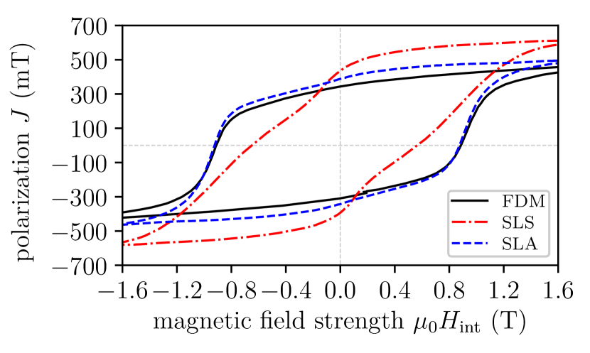
The coercivity of the SLS sample is around % lower compared to the data sheet value of the powder. This is a result of the inhomogeneous microstructure, in particular the grain size distribution [22].
| sample |
|
|
|
|
||||||||
|---|---|---|---|---|---|---|---|---|---|---|---|---|
| powder | – | |||||||||||
| FFF | ||||||||||||
| SLS | ||||||||||||
| SLA |
The capabilities of the different presented AM methods are discussed on a magnetic speed wheel sensing system. Such high precision sensor systems are embedded in many applications, especially in automotive application, e.g. in anti-blocking system (ABS) or engine management systems [24]. A possible design of such speed sensors consist of a magnetic field sensor, e.g. Hall effect or giant magnetoresistance (GMR) sensor, a permanent magnet which provide a bias field and a soft magnetic wheel. Normally, the magnet is underneath the sensor (back-bias magnet) and the rotating soft magnetic wheel modulates the magnetic field of the back-bias magnet. The rotational velocity of the wheel is direct proportional to the modulation of the field. Fig. 4(a) shows a sketch of a possible wheel speed sensing arrangement.
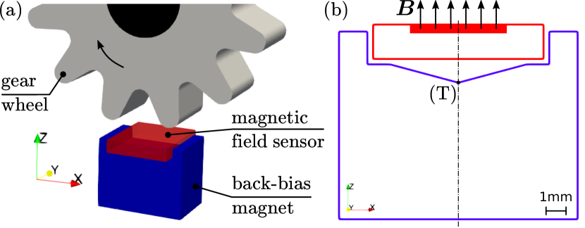
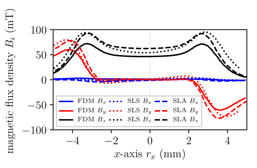
If a GMR sensor is designated to detect the field modulation, some special magnetic design criteria must be considered. GMR sensors are in-plane sensitive and the linear range is very small [25]. This means that the back-bias magnet must have very low magnetic in-plane field components. This can be achieved by a specific design of the magnet. Fig. 4(b) shows the cross-section of a well-known geometry that minimizes the components of the magnetic stray field in and direction in a wide range along the -axis . In this case, an accurate field distribution is more important than a maximum field. Prototyping of such complex magnetic designs is one of the biggest advantage of AM methods.
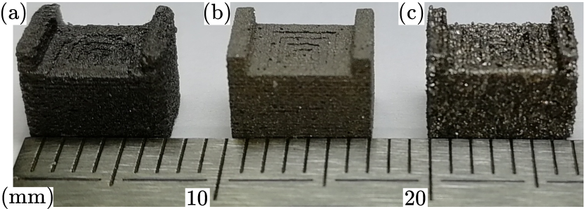
Starting from the design as described above, a back-bias magnet for speed wheel sensing is 3D printed with: (i) FFF, (ii) SLS, and (iii) SLA. The overall size of the magnet is mm3 (LWH). After the printing process, the magnet is magnetized in an electromagnet with a maximum magnetic flux density of T in permanent operation mode. Fig. 5 shows a line scan of the magnetic flux density , mm above the pyramide tip (T) for all three AM methods. The magnetic flux density is measured with a Hall probe and the FFF 3D printer as described in [2]. The magnet printed by FFF has the weakest flux density because of the smaller remanence compared to the other AM methods. However, all three methods show a minimum stray field and along the -axis. A picture of the printed magnets is illustrated in Fig. 6. It is clearly visible that SLA produces the geometrical most accurate prints.
4 Conclusion
AM of magnetic materials with different methods and materials is an active research field. Many groups use the hard magnetic isotropic NdFeB MQP-S powder due to the spherical morphology and robustness against corrosion.
Nevertheless, this publication describes SLA of hard magnetic materials for the first time. Even more, the SLA method is compared to polymer-bonded magnets printed with FFF and sintered magnets printed with SLA. Magnets printed with SLA show the best magnetic performance and a very high surface quality compared to samples printed with FFF or SLS. The modification of the microstructure of the powder during the SLS process is the reason for its lower magnetic performance compared to the other methods. FFF is the most affordable and simplest way to print magnets, but due to the large nozzle diameter, the accuracy of the physical dimensions is limited. Additionally, the lower volumetric mass density compared to the theoretical value is a reason for the lower remanence of the printed magnets.
In summary, it can be said that the MQP-S powder perfectly meets the requirements of the SLA printing process. We can see a huge potential for the manufacturing of complex magnetic designs in a superior quality.
Acknowledgment
The support from CD-Laboratory AMSEN (financed by the Austrian Federal Ministry of Economy, Family and Youth, the National Foundation for Research, Technology and Development) is acknowledged.
References
- Guo and Leu [2013] N. Guo, M. C. Leu, Additive manufacturing: technology, applications and research needs, Frontiers of Mechanical Engineering 8 (2013) 215–243.
- Huber et al. [2016] C. Huber, C. Abert, F. Bruckner, M. Groenefeld, O. Muthsam, S. Schuschnigg, K. Sirak, R. Thanhoffer, I. Teliban, C. Vogler, R. Windl, D. Suess, 3d print of polymer bonded rare-earth magnets, and 3d magnetic field scanning with an end-user 3d printer, Applied Physics Letters 109 (2016) 162401.
- Huber et al. [2017a] C. Huber, C. Abert, F. Bruckner, M. Groenefeld, S. Schuschnigg, I. Teliban, C. Vogler, G. Wautischer, R. Windl, D. Suess, 3d printing of polymer-bonded rare-earth magnets with a variable magnetic compound fraction for a predefined stray field, Scientific Reports 7 (2017a) 9419.
- Huber et al. [2017b] C. Huber, C. Abert, F. Bruckner, C. Pfaff, J. Kriwet, M. Groenefeld, I. Teliban, C. Vogler, D. Suess, Topology optimized and 3d printed polymer-bonded permanent magnets for a predefined external field, Journal of Applied Physics 122 (2017b) 053904.
- Ortner et al. [2017] M. Ortner, C. Huber, N. Vollert, J. Pilz, D. Süss, Application of 3d-printed magnets for magnetic position detection systems, in: SENSORS, 2017 IEEE, IEEE, 2017, pp. 1–3.
- Li et al. [2016] L. Li, A. Tirado, I. C. Nlebedim, O. Rios, B. Post, V. Kunc, R. R. Lowden, E. Lara-Curzio, R. Fredette, J. Ormerod, T. A. Lograsso, M. P. Paranthaman, Big area additive manufacturing of high performance bonded ndfeb magnets, Scientific Reports 6 (2016) 36212.
- von Petersdorff-Campen et al. [2018] K. von Petersdorff-Campen, Y. Hauswirth, J. Carpenter, A. Hagmann, S. Boës, M. Schmid Daners, D. Penner, M. Meboldt, 3d printing of functional assemblies with integrated polymer-bonded magnets demonstrated with a prototype of a rotary blood pump, Applied Sciences 8 (2018) 1275.
- Khatri et al. [2018] B. Khatri, K. Lappe, D. Noetzel, K. Pursche, T. Hanemann, A 3d-printable polymer-metal soft-magnetic functional composite—development and characterization, Materials 11 (2018) 189.
- Patton et al. [2019] M. V. Patton, P. Ryan, T. Calascione, N. Fischer, A. Morgenstern, N. Stenger, B. B. Nelson-Cheeseman, Manipulating magnetic anisotropy in fused filament fabricated parts via macroscopic shape, mesoscopic infill orientation, and infill percentage, Additive Manufacturing 27 (2019) 482–488.
- Kruth et al. [2004] J. Kruth, L. Froyen, J. V. Vaerenbergh, P. Mercelis, M. Rombouts, B. Lauwers, Selective laser melting of iron-based powder, Journal of Materials Processing Technology 149 (2004) 616 – 622. 14th Interntaional Symposium on Electromachining (ISEM XIV).
- Attar et al. [2015] H. Attar, K. G. Prashanth, L.-C. Zhang, M. Calin, I. V. Okulov, S. Scudino, C. Yang, J. Eckert, Effect of powder particle shape on the properties of in situ ti–tib composite materials produced by selective laser melting, Journal of Materials Science & Technology 31 (2015) 1001–1005.
- Fischer et al. [1996] R. Fischer, T. Schrefl, H. Kronmüller, J. Fidler, Grain-size dependence of remanence and coercive field of isotropic nanocrystalline composite permanent magnets, Journal of magnetism and magnetic materials 153 (1996) 35–49.
- Engelmann et al. [1997] H. Engelmann, A. Kim, G. Thomas, Microstructure and magnetic effects of small cu additions to (nd, dy) feb magnets, Scripta materialia 36 (1997) 55–62.
- Kronmüller et al. [1988] H. Kronmüller, K.-D. Durst, M. Sagawa, Analysis of the magnetic hardening mechanism in re-feb permanent magnets, Journal of magnetism and magnetic materials 74 (1988) 291–302.
- Radulov et al. [2019] I. Radulov, V. Popov Jr, A. Koptyug, F. Maccari, A. Kovalevsky, S. Essel, J. Gassmann, K. Skokov, M. Bamberger, Production of net-shape mn-al permanent magnets by electron beam melting, Additive Manufacturing 30 (2019) 100787.
- Huber et al. [2018] C. Huber, M. Goertler, C. Abert, F. Bruckner, M. Groenefeld, I. Teliban, D. Suess, Additive manufactured and topology optimized passive shimming elements for permanent magnetic systems, Scientific reports 8 (2018) 14651.
- Mikler et al. [2017] C. Mikler, V. Chaudhary, T. Borkar, V. Soni, D. Jaeger, X. Chen, R. Contieri, R. Ramanujan, R. Banerjee, Laser additive manufacturing of magnetic materials, JOM 69 (2017) 532–543.
- Zhang et al. [2013] B. Zhang, N.-E. Fenineche, H. Liao, C. Coddet, Magnetic properties of in-situ synthesized feni 3 by selective laser melting fe-80% ni powders, Journal of Magnetism and Magnetic Materials 336 (2013) 49–54.
- White et al. [2017] E. M. H. White, A. G. Kassen, E. Simsek, W. Tang, R. T. Ott, I. E. Anderson, Net shape processing of alnico magnets by additive manufacturing, IEEE Transactions on Magnetics 53 (2017) 1–6.
- Jaćimović et al. [2017] J. Jaćimović, F. Binda, L. G. Herrmann, F. Greuter, J. Genta, M. Calvo, T. Tomše, R. A. Simon, Net shape 3d printed ndfeb permanent magnet, Advanced Engineering Materials (2017).
- Kolb et al. [2016] T. Kolb, F. Huber, B. Akbulut, C. Donocik, N. Urban, D. Maurer, J. Franke, Laser beam melting of ndfeb for the production of rare-earth magnets, in: Electric Drives Production Conference (EDPC), 2016 6th International, IEEE, 2016, pp. 34–40.
- Huber et al. [2019] C. Huber, H. Sepehri-Amin, M. Goertler, M. Groenefeld, I. Teliban, K. Hono, D. Suess, Coercivity enhancement of selective laser sintered ndfeb magnets by grain boundary infiltration, Acta Materialia 172 (2019) 66–71.
- Cuchet et al. [2017] C. Cuchet, A. Muster, P. Germano, Y. Perriard, Soft magnets implementation using a stereolithography-based 3d printer, in: 2017 20th International Conference on Electrical Machines and Systems (ICEMS), IEEE, 2017, pp. 1–5.
- Elian and Theuss [2014] K. Elian, H. Theuss, Integration of polymer bonded magnets into magnetic sensors, in: Electronics System-Integration Technology Conference (ESTC), 2014, 2014, pp. 1–5.
- Lenz and Edelstein [2006] J. Lenz, S. Edelstein, Magnetic sensors and their applications, IEEE Sensors journal 6 (2006) 631–649.