Feedback cooling of a room temperature mechanical oscillator
close to its motional groundstate
Abstract
Preparing mechanical systems in their lowest possible entropy state, the quantum groundstate, starting from a room temperature environment is a key challenge in quantum optomechanics. This would not only enable creating quantum states of truly macroscopic systems, but at the same time also lay the groundwork for a new generation of quantum limited mechanical sensors in ambient environments. Laser cooling of optomechanical devices using the radiation pressure force combined with cryogenic pre-cooling has been successful at demonstrating groundstate preparation of various devices, while a similar demonstration starting from a room temperature environment remains an outstanding goal. Here we combine integrated nanophotonics with phononic bandgap engineering to simultaneously overcome prior limitations in the isolation from the surrounding environment, the achievable mechanical frequencies, as well as limited optomechanical coupling strength, demonstrating a single-photon cooperativity of 200. This new microchip technology allows us to feedback cool a mechanical resonator to around 1 mK, near its motional groundstate, from room temperature. Our experiment marks a major step towards accessible, widespread quantum technologies with mechanical resonators.
The last decade has seen immense progress on observing quantum effects with microfabricated mechanical oscillators O’Connell et al. (2010); Palomaki et al. (2013); Hong et al. (2017); Riedinger et al. (2018); Ockeloen-Korppi et al. (2018); Marinković et al. (2018). This is not only of significant interest for understanding the fundamental aspects of quantum physics in macroscopic objects, but also for the potential of using mechanical systems for quantum information processing tasks and as novel quantum sensors Norte et al. (2018). Excess classical (i.e. thermal) noise typically obscures the quantum features of these devices, thus limiting their usefulness and practical adoption for quantum limited sensing. Groundstate cooling can alleviate this problem, but so far has only been possible by pre-cooling the devices using cryogenic methods Chan et al. (2011); Teufel et al. (2011); Underwood et al. (2015); Peterson et al. (2016); Rossi et al. (2018). The main limitations preventing to reach this regime from room temperature include insufficient isolation from the surrounding environment and too low mechanical frequencies, which can be formulated into the condition of the product of the mechanical frequency and its quality factor Marquardt et al. (2007). In addition, the optomechanical coupling rate also plays a dominant role in the ability to efficiently laser cool the motion of a resonator. There are several approaches focusing on overcoming these limitations. In particular, experiments featuring optically levitated nanospheres have come to within a few thermal phonons of the mechanical groundstate recently Delić et al. (2019); Tebbenjohanns et al. (2019a); Conangla et al. (2019); Tebbenjohanns et al. (2019b). While the absence of any physical attachment to the environment allows trapped nanospheres to exhibit extremely large quality factors, they require UHV systems and complex stabilization mechanisms for their optical traps, making them impractical as sensors and for other applications. Chip-based mechanical oscillators have recently also been shown to feature competitively large mechanical quality factors at room temperature with , most prominently in high-stress silicon nitride membranes Norte et al. (2016); Reinhardt et al. (2016); Tsaturyan et al. (2017). Here, similar limitations as with levitated nanospheres, such as mirror noise Liu and Thorne (2000); Harry et al. (2006), exist, as well as the requirement to use bulky setups for optical readout.
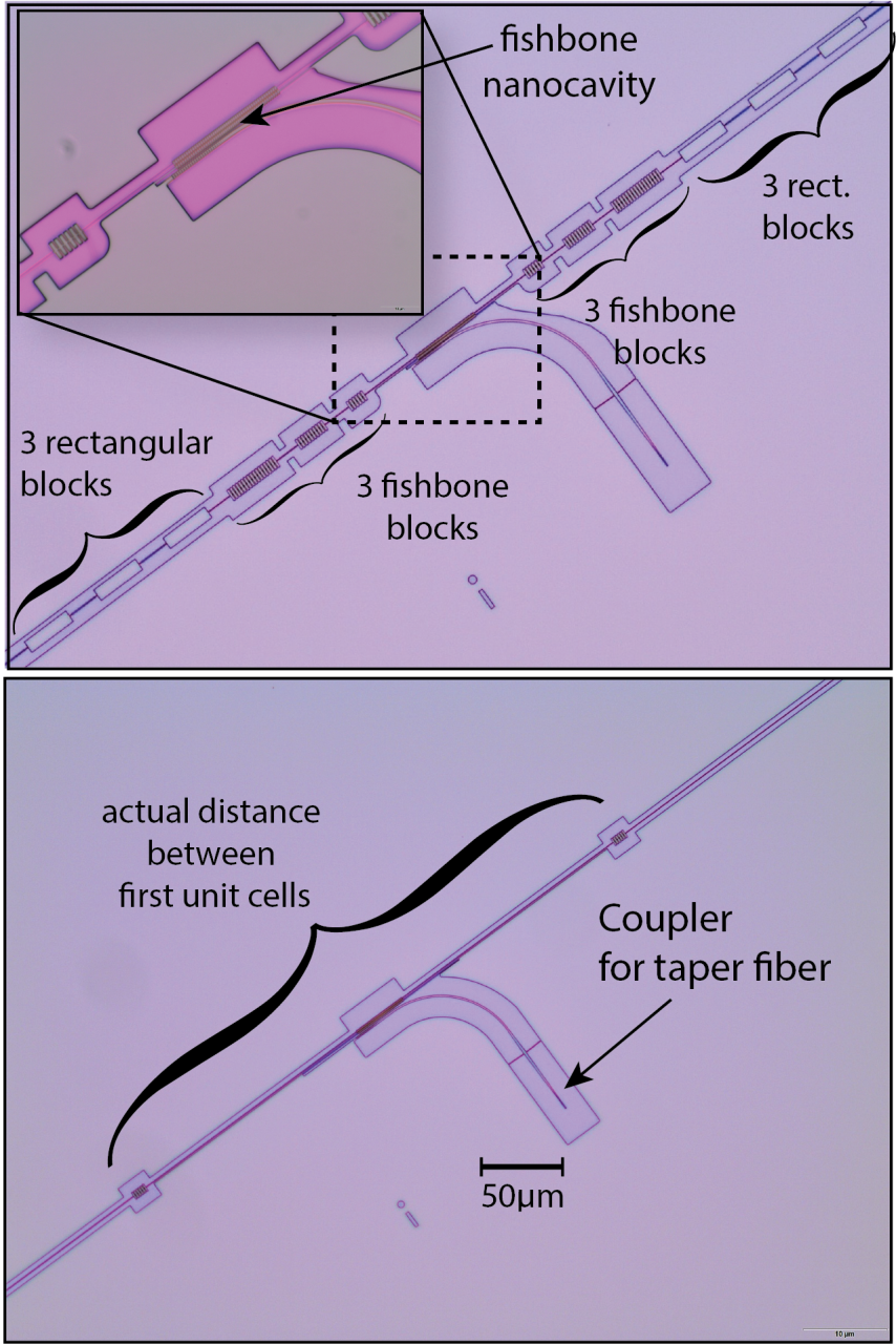
In this work, we develop a new type of fully integrated optomechanical structure that allows us to significantly increase the mechanical quality factor of a high-frequency in-plane mode, while also allowing to realize a coupled opto-mechanical cavity used for on-chip optical read-out of the motion. We measure a , approaching the performance of the best out-of-plane mechanical resonators Ghadimi et al. (2018); Rossi et al. (2018), combined with an optomechanical coupling of GHz/nm, enabling us to cool the mechanical mode from room temperature to 1.2 mK. This corresponds to a thermal mode occupation of less than 27 phonons, a reduction by more than 5 orders of magnitude in the effective temperature. Our novel design applies previous discoveries on the dominant role of bending losses Unterreithmeier et al. (2010); Ghadimi et al. (2018) and results in a device that resembles a fishbone-like photonic and phononic structure (cf. Figure 1a).
Significant progress has been made over the last years in understanding and mitigating the losses in integrated (opto-) mechanical structures, resulting in experimental demonstrations of ultra-high devices. In particular, bending loss has been shown to be one of the dominant limiting mechanisms for mechanical quality factors in 1D high-stress silicon nitride structures Unterreithmeier et al. (2010). Various approaches in strain Norte et al. (2016); Reinhardt et al. (2016) and mode shape engineering Ghadimi et al. (2018) have recently succeeded in achieving ultrahigh- mechanical resonators. By using adiabatically chirped phononic crystals for example Ghadimi et al. (2018), the mechanical mode is localized in the center of the beam and the bending can significantly be reduced, leading to increases in . While this concept works very well for the out-of-plane motion, it is much more challenging for an in-plane mode Ghadimi (2018). This is due to the loss being proportional to the cube of the thickness in the motional direction Ghadimi et al. (2018), which for the in-plane mode is equivalent to the width of the structure ), with being the displacement. In practice, there are several parts of an optomechanical structure that require a certain minimum width, such as the phononic crystal itself, which is partly comprised of wide blocks of material. The bending of these very wide blocks results in large mechanical dissipations. Furthermore, in order to form a good optical cavity, the photonic crystal at the center of the structure also requires a minimum width, which is comparable to the optical wavelength Krause et al. (2015). Both factors largely reduce the attainable mechanical quality factor. With our new fishbone design we minimize in the parts with maximal bending, allowing us to significantly reduce , and hence significantly increase the mechanical quality factor of the mechanical in-plane modes.
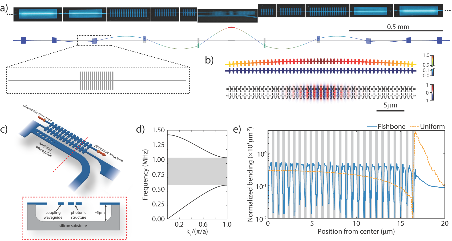
Our structure is fabricated from a 350 nm thick high-stress (1.3 GPa) silicon nitride layer deposited on a silicon handle wafer. As shown in Figure 1a, it is based on the differential motion of two strings, where one of them is significantly longer (2.6 mm) than the other (115 m). The longer string of this zipper structure is connected to the chip through a phononic crystal, with a bandgap for the in-plane mode between 610 kHz and 1.10 MHz (see Figure 1d). This design forms a defect in the center, introducing confined modes with frequencies within the bandgap, significantly reducing the losses of these modes. As the amplitude of the modes of interest is largest in the center of the structure, we reduce its bending by introducing an adiabatic transition of the unit cells of the phononic crystals. This results in a weaker confinement and smaller bending close to the center Ghadimi et al. (2018). As mentioned above, this does however not immediately result in a high quality factor of the in-plane modes, as the width of the structure close to the bending areas becomes important. We therefore design the overall device as a string with a width of only 165 nm, limited by our fabrication process. When adding the phononic crystal we avoid wide and rigid regions in the design, segmenting the blocks closest to the center into a fishbone-like structure.
A similar approach is also taken for the central photonic crystal used to read-out the mechanical motion. Instead of a traditional photonic structure with holes in a wavegeuide Krause et al. (2015), we achieve an alternating index contrast through a fishbone design. The wider parts are roughly 1 m in width, while the narrow ones between the teeth have a width of only 165 nm. This geometry localizes the bending to the narrow parts (cf. Figure 1e), significantly reducing the overall bending losses. For comparison, we observe a typical enhancement of by more than a factor of 5 between devices with and without the photonic fishbone structure.
The optical cavity is formed between the long and short strings and the optical field is confined within the gap formed by the fishbones and designed to operate at a wavelength of around nm. Due to the strong confinement, the resonance frequency of the cavity is very sensitive to the gap size. In the simulation, shown in Figure 1b, we obtain an optomechanical coupling strength GHz/nm, with the cavity frequency, for a typical 200 nm gap. Combining with the localized mechanical mode of interest, which has small effective mass kg, we obtain a single photon coupling rate kHz. The resulting optimized structure features a 16.5 m long photonic crystal cavity, while the overall structure has a length of 2.6 mm.
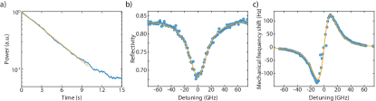
We design the mechanical defect mode at a frequency kHz. A ringdown measurement of this mode in mbar vacuum, shows a quality factor of (cf. SI), yielding . The total optical resonance’s ( nm) linewidth is measured to be GHz, and the coupling rate to an adjacent optical waveguide GHz. The strongly over-coupled cavity ensures that most of the light in the cavity is reflected back into the waveguide, which is necessary to achieve high detection efficiency. To further characterize the device, we measure the optical spring effect (see SI for details), allowing us to experimentally determine a single photon coupling rate of kHz, corresponding to an optomechanical coupling of GHz/nm, in good agreement with simulations. We determine the single photon cooperativity of our device , which represents the relative strength of the single photon interactions against any loss channels, a key characteristic of the system Krause et al. (2015); Wilson et al. (2015).
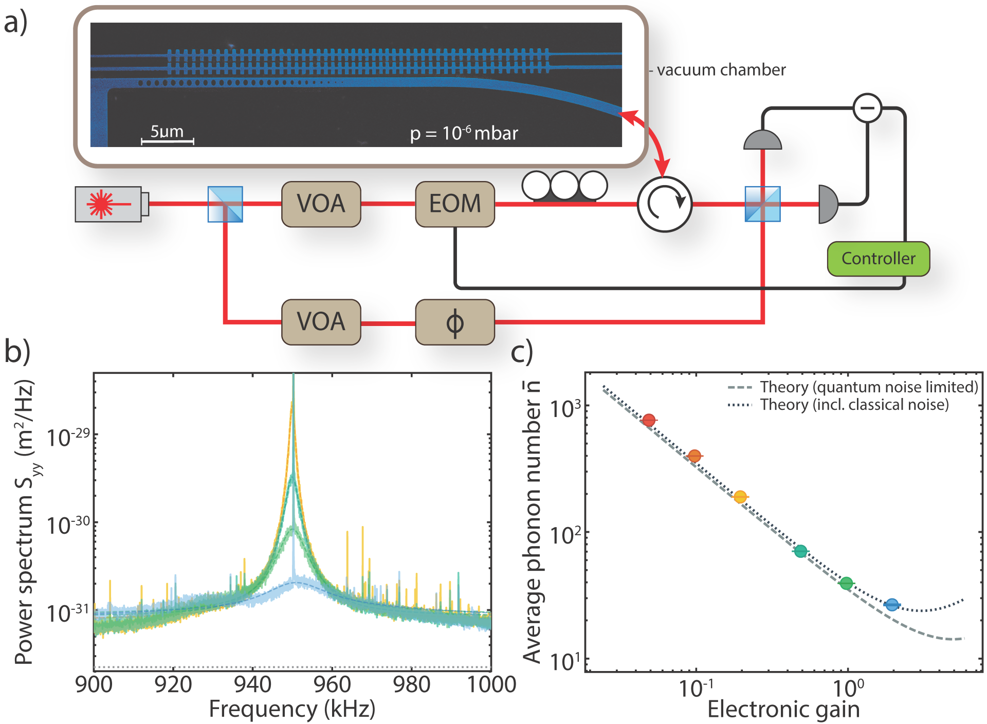
In this unresolved side band regime Aspelmeyer et al. (2014), an active feedback cooling scheme can be used to reduce the thermal energy of the mechanical oscillator Kleckner and Bouwmeester (2006); Rossi et al. (2018). In this scheme, unlike in the traditional cavity cooling approach Chan et al. (2011), the extremely large bandwidth of the optical cavity allows to retrieve information on the motion of the mechanical resonator at a high rate. In our experiment, we measure the position of the mechanics and process it in real-time, using the resulting signal to actively control the optical input power into the optomechanical cavity. The modulation of the intensity changes the radiation-pressure force, hence allowing to control and actively cool the mechanics itself. Figure 3a shows a sketch and description of our setup used to demonstrate such feedback cooling of our mechanical resonator. The measured signal containing the information on the position of the mechanical oscillator is sent to an FPGA controller (RedPitaya 125-14), with its output directly connected to an electro-optical intensity modulator just before the device. The FPGA control allows us to implement an almost arbitrarily complicated feedback filter. We apply a derivative filter with a order underdamped low-pass filter to cool the mechanical defect mode. The feedback phase at the resonance frequency is tuned to be . Due to a small delay in the system, applying this signal directly would heat other nearby mechanical modes and make the system unstable. We therefore cascade a series of notch filters to tune the phase response locally, which provides a weak cooling over the surrounding modes (cf. Figure 2). The total delay of the feedback loop is measured to be 0.49 s.
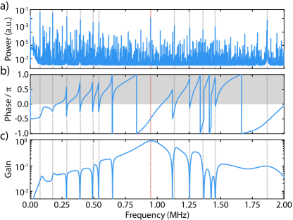
Figure 3b shows the calibrated displacement power spectrum () of the mechanical oscillator with different levels of cooling from a bath at room temperature. We keep the cavity photon number fixed at , while increasing the gain of the feedback filter to increase the amount of feedback. The mechanical peak amplitude reduces and broadens, corresponding to a cooling of the mode of interest. The curves are then fitted and we extract the displacement spectrum Rossi et al. (2018); Krause et al. (2015). This allows us to calculate the average phonon number , which is shown as a function of electronic gain in Figure 3c. The lowest occupation we obtain is , reduced from at room temperature. We note that our measurements are not quantum-noise-limited in this experiment, resulting in a slightly increased phonon occupancy compared to the theoretically expected value. This additional noise floor results from the optical fiber touching the waveguide and introducing broadband mechanical modes. These mechanical waveguide modes shift the resonance frequency of the cavity weakly, resulting in an increase of the detection noise. At high gain, this noise is fed into the mechanics and limits the cooling efficiency. Unlike in the ideal case of a quantum-noise-limited measurement, increasing the input optical power does not reduce the classical noise and hence it does not lead to more efficient cooling. Using different types of coupling methods or re-designing the waveguide will allow us to reduce the classical noise further, allowing us to, in principle, cool to an occupation of , with everything else left unchanged.
In order to get even closer to the groundstate in the continuous feedback cooling scheme, the measurement rate () has to be comparable or larger than the decoherence rates in the system, i.e. the thermal decoherence () and the back-action rate (, where ) Wilson et al. (2015). Here, is the overall detection efficiency, which for our experiment is , while , hence making the thermal component the dominant decoherence channel. Excluding classical noise, we find Wilson et al. (2015), which is orders of magnitude larger than in previous similar experiments Krause et al. (2015).
Several approaches to increasing this ratio exist. For example, by redesigning the coupling waveguide to obtain a quantum-noise-limited measurement, the intracavity photon number can be raised further, and is eventually only bound by absorption heating. Increasing the optomechanical coupling rate can be achieved by improving the fabrication and reducing the gap size between the strings forming the optical cavity. A reduction of the gap to 100 nm yields GHz/nm, which is more than twice the current value. Another way is to further reduce the thermal decoherence rate, through device improvements. Our current design is not optimized to maximize the stress Norte et al. (2016), which would lead to more stored energy, increasing . At the moment, the maximum simulated stress in the structure is 1.5 GPa, which is still far below the yield strength of SiN (6 GPa). Higher stress can also be achieved through an overall longer beam, while at the same time allowing for more adiabatic chirping in the geometry, which would further reduce mechanical losses. Combining all of these approaches should allow to reach the quantum groundstate. In partiular, moderately increasing the mechanical quality factor to , would lead to an increase of to 0.06 and the phonon number could be reduced to 6. Together with a reasonable reduction of the gap to 100 nm and a small increase of the cavity photon number to 200, a phonon occupation around 3 will be achievable. Further improvements in to Tsaturyan et al. (2017); Ghadimi et al. (2018) will finally enable phonon numbers below unity starting from room temperature.
In summary, we have designed and fabricated a novel, fully integrated optomechanical system, featuring a fishbone-like photonic and phononic structure, with a of an in-plane mechanical mode combined with a large optomechanical coupling rate of kHz. We use this device to demonstrate active-feedback cooling close to the quantum groundstate of motion, starting from room temperature. By tuning the FPGA-based feedback filter, we stabilize spurious modes that strongly couple to the optics, allowing us to reach an effective mode temperature of 1.2 mK, corresponding to less than 27 phonons. Further improvements in the noise performance of our setup, together with enhancements of and optomechanical coupling, should allow for these structures to be cooled fully into their groundstate, which will enable mechanical quantum experiments at ambient temperatures. In addition, the simplicity in fabrication of our devices, consisting of a single SiN layer on chip only, combined with their fully integrated on-chip character, makes them ideal candidates for quantum sensing applications Krause et al. (2015); Norte et al. (2018).
Acknowledgements.
We would like to thank Bas Hensen, Alex Krause, Igor Marinković, Rob Stockill, and Andreas Wallucks for valuable discussions and also acknowledge assistance from the Kavli Nanolab Delft. This work is further supported by the Foundation for Fundamental Research on Matter (FOM) Projectruimte grants (15PR3210, 16PR1054), the European Research Council (ERC StG Strong-Q, 676842), the EMPIR programme co-financed by the Participating States and from the European Union’s Horizon 2020 research and innovation programme, and by the Netherlands Organization for Scientific Research (NWO/OCW), as part of the Frontiers of Nanoscience program, as well as through a Vidi grant (680-47-541/994). This project is part of ATTRACT that has received funding from the European Union’s Horizon 2020 Research and Innovation Programme. J.G. gratefully acknowledges support through a Casimir PhD fellowship.References
- O’Connell et al. (2010) A. D. O’Connell, M. Hofheinz, M. Ansmann, R. C. Bialczak, M. Lenander, E. Lucero, M. Neeley, D. Sank, H. Wang, M. Weides, J. Wenner, J. M. Martinis, and A. N. Cleland, Nature 464, 697 (2010).
- Palomaki et al. (2013) T. Palomaki, J. Teufel, R. Simmonds, and K. Lehnert, Science 342, 710 (2013).
- Hong et al. (2017) S. Hong, R. Riedinger, I. Marinković, A. Wallucks, S. G. Hofer, R. A. Norte, M. Aspelmeyer, and S. Gröblacher, Science 358, 203 (2017).
- Riedinger et al. (2018) R. Riedinger, A. Wallucks, I. Marinković, C. Löschnauer, M. Aspelmeyer, S. Hong, and S. Gröblacher, Nature 556, 473 (2018).
- Ockeloen-Korppi et al. (2018) C. F. Ockeloen-Korppi, E. Damskägg, J.-M. Pirkkalainen, M. Asjad, A. A. Clerk, F. Massel, M. J. Woolley, and M. A. Sillanpää, Nature 556, 478 (2018).
- Marinković et al. (2018) I. Marinković, A. Wallucks, R. Riedinger, S. Hong, M. Aspelmeyer, and S. Gröblacher, Phys. Rev. Lett. 121, 220404 (2018).
- Norte et al. (2018) R. A. Norte, M. Forsch, A. Wallucks, I. Marinković, and S. Gröblacher, Phys. Rev. Lett. 121, 030405 (2018).
- Chan et al. (2011) J. Chan, T. P. M. Alegre, A. H. Safavi-Naeini, J. T. Hill, A. Krause, S. Gröblacher, M. Aspelmeyer, and O. Painter, Nature 478, 89 (2011).
- Teufel et al. (2011) J. D. Teufel, T. Donner, D. Li, J. W. Harlow, M. S. Allman, K. Cicak, A. J. Sirois, J. D. Whittaker, K. W. Lehnert, and R. W. Simmonds, Nature 475, 359 (2011).
- Underwood et al. (2015) M. Underwood, D. Mason, D. Lee, H. Xu, L. Jiang, A. B. Shkarin, K. Børkje, S. M. Girvin, and J. G. E. Harris, Phys. Rev. A 92, 061801(R) (2015).
- Peterson et al. (2016) R. W. Peterson, T. P. Purdy, N. S. Kampel, R. W. Andrews, P.-L. Yu, K. W. Lehnert, and C. A. Regal, Phys. Rev. Lett. 116, 063601 (2016).
- Rossi et al. (2018) M. Rossi, D. Mason, J. Chen, Y. Tsaturyan, and A. Schliesser, Nature 563, 53 (2018).
- Marquardt et al. (2007) F. Marquardt, J. P. Chen, A. A. Clerk, and S. M. Girvin, Phys. Rev. Lett. 99, 093902 (2007).
- Delić et al. (2019) U. Delić, M. Reisenbauer, D. Grass, N. Kiesel, V. Vuletić, and M. Aspelmeyer, Phys. Rev. Lett. 122, 123602 (2019).
- Tebbenjohanns et al. (2019a) F. Tebbenjohanns, M. Frimmer, A. Militaru, V. Jain, and L. Novotny, Phys. Rev. Lett. 122, 223601 (2019a).
- Conangla et al. (2019) G. P. Conangla, F. Ricci, M. T. Cuairan, A. W. Schell, N. Meyer, and R. Quidant, Phys. Rev. Lett. 122, 223602 (2019).
- Tebbenjohanns et al. (2019b) F. Tebbenjohanns, M. Frimmer, V. Jain, D. Windey, and L. Novotny, arXiv:1908.05079 (2019b).
- Norte et al. (2016) R. A. Norte, J. P. Moura, and S. Gröblacher, Phys. Rev. Lett. 116, 147202 (2016).
- Reinhardt et al. (2016) C. Reinhardt, T. Müller, A. Bourassa, and J. C. Sankey, Phys. Rev. X 6, 021001 (2016).
- Tsaturyan et al. (2017) Y. Tsaturyan, A. Barg, E. S. Polzik, and A. Schliesser, Nature Nanotechn. 12, 776 (2017).
- Liu and Thorne (2000) Y. T. Liu and K. S. Thorne, Phys. Rev. D 62, 122002 (2000).
- Harry et al. (2006) G. M. Harry, H. Armandula, E. Black, D. R. M. Crooks, G. Cagnoli, J. Hough, P. Murray, S. Reid, S. Rowan, P. Sneddon, M. M. Fejer, R. Route, and S. D. Penn, Appl. Opt. 45, 1569 (2006).
- Krause et al. (2015) A. G. Krause, T. D. Blasius, and O. Painter, arXiv:1506.01249 (2015).
- Ghadimi et al. (2018) A. H. Ghadimi, S. A. Fedorov, N. J. Engelsen, M. J. Bereyhi, R. Schilling, D. J. Wilson, and T. J. Kippenberg, Science 360, 764 (2018).
- Unterreithmeier et al. (2010) Q. P. Unterreithmeier, T. Faust, and J. P. Kotthaus, Phys. Rev. Lett. 105, 027205 (2010).
- Ghadimi (2018) A. H. Ghadimi, Ultra-coherent nano-mechanical resonators for quantum optomechanics at room temperature, Ph.D. thesis, École polytechnique fédérale de Lausanne (2018).
- Wilson et al. (2015) D. J. Wilson, V. Sudhir, N. Piro, R. Schilling, A. Ghadimi, and T. J. Kippenberg, Nature 524, 325 (2015).
- Aspelmeyer et al. (2014) M. Aspelmeyer, T. J. Kippenberg, and F. Marquardt, Rev. Mod. Phys. 86, 1391 (2014).
- Kleckner and Bouwmeester (2006) D. Kleckner and D. Bouwmeester, Nature 444, 75 (2006).
- Gröblacher et al. (2013) S. Gröblacher, J. T. Hill, A. H. Safavi-Naeini, J. Chan, and O. Painter, Appl. Phys. Lett., 103, 181104 (2013).
- Chan (2012) J. Chan, Laser cooling of an optomechanical crystal resonator to its quantum ground state of motion, Ph.D. thesis, California Institute of Technology (2012).
- Johnson et al. (2002) S. G. Johnson, M. Ibanescu, M. A. Skorobogatiy, O. Weisberg, J. D. Joannopoulos, and Y. Fink, Phys. Rev. E 65, 066611 (2002).
- Ghadimi et al. (2017) A. H. Ghadimi, D. J. Wilson, and T. J. Kippenberg, Nano Lett. 17, 3501 (2017).
I Supplementary Information
I.1 Device design
For our design, we first set the geometry of the photonic crystal as the fishbone structure. We then fix the width of the narrow part of the photonic crystal to nm, a width that can easily be fabricated with high yield. The photonic crystal consists of adiabatically chirped unit cells, with a defect region at the center and mirror regions at the ends. We then perform finite element simulations (FEM) of the optical properties of a unit cell of the mirror region and the defect, using COMSOL. The free parameters are the period of the unit cells at the defect region and at the mirror region, as well as the width and the ratio between the length of the wide part and the period . These parameters are tuned such that we obtain a bandgap around 1550 nm for TE-like modes for the mirror. We design the defect such that the lower-band crosses the center of this bandgap. We also set transition of the parameters to follow a Gaussian function, , where is the corresponding parameter of the n-th unit cell. Here is the parameter for the unit cell corresponding to the mirror region, while is the unit cell at the center. The parameter determines the adiabaticity of the transition, which we set to 9 in our case. With this initial design we then run an optimization algorithm Chan (2012) maximizing , where is calculated using the moving boundary effect Johnson et al. (2002). For the structure we use in this work, the designed parameters are listed in Table 1.
| Parameter | ||
|---|---|---|
| 590 nm | 691 nm | |
| 992 nm | 992 nm | |
| 0.461 | 0.399 |
| Parameter | (fishbone) | (fishbone) | (block) | (block) |
| 283 m | 91.6 m | 283 m | 91.6 m | |
| 170 nm | 550 nm | 170 nm | 550 nm | |
| 480 nm | 746 nm | 288 nm | 746 nm | |
| 0.035 | 0.29 | -0.1 | 0.29 |
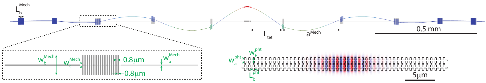
The mechanical simulations are also performed using COMSOL, where the width of the initial string is again chosen to be 165 nm. We first simulate the band structure for the unit cell closest to the clamping region and a unit cell of the last phononic fishbone structure. In order to reduce the parameter space for the fishbone structure, both its vertical width and the distance between individual fins is fixed to 0.8 m. Within the fishbone structure, the width of the string connecting the fins is set to 165 nm for the first unit cell, and 250 nm for the mirror region. The parts of strings closest to the rectangular blocks are narrowed down to follow the same transition. Through the simulations, we find bandgaps for the block and fishbone structure, respectively. Finally, we run a full mechanical simulation of the whole assembled long string. For the device presented here, 3 unit cells on each side have the fishbone structure, while another 3 are rectangular blocks. As the stress differs between the individual unit cell and the complete simulations, due to the finite length of the structure, the actual bandgap of the device deviates slightly. We manually adjust the length of the string connecting to the photonic crystal in order to obtain the right mode. We then run another optimization, this time maximizing , where is evaluated as the ratio between the stored elastic energy and the bending loss Ghadimi (2018). We also set a bound on in the optimization in order to limit the mechanical frequency range. The main parameters and the corresponding values are shown in Table 2. As before, the same Gaussian transition is used. parameters. Note that there is no adiabatic transition between the fishbone phononic structure and the rectangular blocks. Instead, we use two sets of parameters defining their geometries.
I.2 Device fabrication & characterization
Our devices are fabricated from a 350 nm thick high-stress silicon nitride film deposited in an LPCVD furnace on silicon. The pattern is first generated using standard electron beam lithography and then transferred into the silicon nitride layer using a CHF3 plasma etch. Next, we clean the chip in a piranha solution and use hydrofluoric acid to remove any oxidation. Finally, we undercut our structures using a fluorine-based dry release Norte et al. (2018). We would like to highlight the simplicity of the fabrication process, requiring a minimal amount of steps in order to make the suspended structure, completely avoiding the need for complex multilayered processes Ghadimi et al. (2017).
In order to measure the mechanical and optical properties of our device, we perform a mechanical ringdown measurement, as well as a wavelength sweep of the optical resonance (see Figure S1a,b), respectively. We determine the optomechanical coupling rate by measuring the optical spring effect of the mechanical mode as a function of laser detuning (cf. Figure S1c).
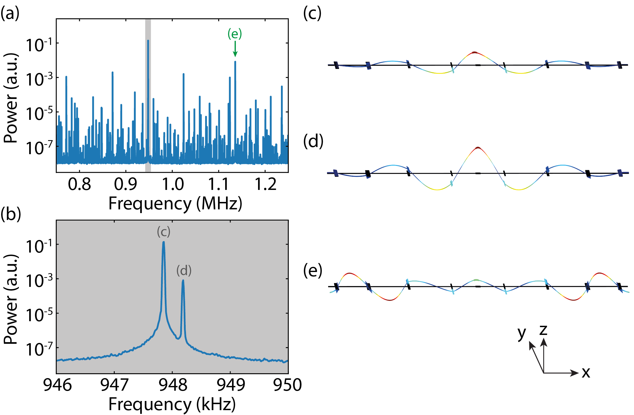
The mechanical spectrum close to our mode of interest is shown in Figure S3a, from which we identify and verify that the mechanical mode we measure is the correct in-plane mechanical mode we design. A zoom-in of the spectrum around 948 kHz (gray region) is plotted in Figure S3b. Due to the single-layer geometry, the in-plane mode (left) has a large optomechanical coupling, while the coupling of the out-of-plane mode (right) is weak. The out-of-plane mode has a slightly higher frequency, which agrees with our simulations (see c and d). We further confirm the mode by comparing it with a higher order in-plane mode (green arrow, Figure S3e), whose frequency is 19 kHz higher, which is also in excellent agreement with simulations (20 kHz higher).