A Tunably Compliant Origami Mechanism for Dynamically Dexterous Robots
Abstract
We present an approach to overcoming challenges in dynamical dexterity for robots through tunable origami structures. Our work leverages a one-parameter family of flat sheet crease patterns that folds into origami bellows, whose axial compliance can be tuned to select desired stiffness. Concentrically arranged cylinder pairs reliably manifest additive stiffness, extending the tunable range by nearly an order of magnitude and achieving bulk axial stiffness spanning 200–1500 N m-1 using 8 mil thick polyester-coated paper. Accordingly, we design origami energy-storing springs with a stiffness of 1035 N m-1 each and incorporate them into a three degree-of-freedom (DOF) tendon-driven spatial pointing mechanism that exhibits trajectory tracking accuracy less than 15% rms error within a (2 cm)3 volume. The origami springs can sustain high power throughput, enabling the robot to achieve asymptotically stable juggling for both highly elastic (1 kg resilient shotput ball) and highly damped (“medicine ball”) collisions in the vertical direction with apex heights approaching 10 cm. The results demonstrate that “soft” robotic mechanisms are able to perform a controlled, dynamically actuated task.
I Introduction
Over decades of robot manipulation [1] and locomotion [2] research, the term dynamical dexterity has come to mean the programmed [3] exchange of work and information at high temporal rates [4]. Indeed, sensorimotor dexterity [5] is essential to the quality of our daily life [6], specifically in the high-strength regime [7]. As robots begin to enter the unstructured workplace, their users’ expectation of companionable dexterity will continue to sharpen the intrinsic conflict between the need for more actuated degrees of freedom and the requirement of high power density [8], whose limits in the relevant highly energetic and high strength regime have long manifested as the first scarce resource in conventional robot actuation technologies [9].
The use of soft materials of varied shape and tunable compliance enjoys an active literature in contemporary robotics [10] and beyond [11] as a method for introducing both high maneuverability and resilience directly into the body of a robot. However, while compliant elastomeric robots have have occasionally been demonstrated to produce fast, dynamic [12], and even explosive [13] maneuvers, the high damping and high fatigue properties in these elastomers often limit these maneuvers to a single use. Meanwhile, sustained dynamic motions needed for tasks such as juggling, hopping, and trotting, remain out of reach for most soft robots.
Origami-inspired approaches to replacing [14, 15, 16] or enhancing [17] soft-bodied machines promise to address these challenges in achieving repeated, dynamic movement. Past research in this field has demonstrated durable actuators from origami cylinders, yielding lightweight structures [18, 19] patterned by high compliance folds. The resulting actuators assert high specific force [20] over a large volume-to-mass workspace [21], and bear substantial loads [17] while resisting unwanted (e.g., torsional) disturbances [22]. However, to date, origami robots have been designed as though with rigid linkages joined through rotational folds, without taking into consideration of the additional compliance and resiliency provided by the sheet material itself. As a result, they have been unable to match the power densities of the rigid-body counterparts.
In this paper, we explore the prospects for integrating tunable compliance and highly energetic anisotropic designs in the drive train of a three DOF robotic limb through the lens of the vertical one-juggle [1], a well established route toward dynamically dexterous manipulation and locomotion [23]. Through geometric designs of an origami bellow pattern [24], we aim to achieve elastic axial compliance with reduced material weight and mitigation of energetic loss, thus producing a “soft” spring robotic juggler capable of high-power operation. It has been suggested in origami mechanics [25, 26] that the resistance of an origami design to static loading conditions can be tuned through appropriate choices of its geometric parameters. Here, we demonstrate that the dynamic response of an origami pattern can also be tuned, and that the resulting structure is in fact capable of transducing the high power densities required for dynamical dexterity.
Specifically, we leverage the Reconfigurable Expanding Bistable Origami (REBO) pattern [24], which was originally designed for geometric reconfiguration. Interestingly, we find that small changes in the fold pattern alter not only the geometry of the structure, but also its rigidity. Thus, we manipulate the REBO design parameters for a dynamic juggling task and introduce a concentric pairing of the REBO cylinders to enhance stiffness. We drive three such concentrically paired cylinders to achieve stiffness and compress each via a conventionally actuated tendon. The resulting three-DOF “limb” achieves reasonably good trajectory tracking (less than 15% rms error) within a workspace whose actuated volume is limited to a small fraction of its kinematically achievable span by the torque output of the brushless DC motors. Nevertheless, this volume affords adequate travel and the paired REBO cylinders transduce sufficiently high power to achieve asymptotically stable vertical juggling of balls of varied mass and resilience.
In summary, the contribution of this work is the development, analysis, and application of a new approach for dynamically dexterous manipulation; it substitutes an origami structure for a conventional spring, storing sufficient energy and transducing it with sufficient power and force to juggle stably a 1 kg mass to a height selectable over a range of nearly 10 cm, from initial conditions within a simlarly large basin of attraction.
II Origami Module Design
II-A Parameterized Programmable Crease Pattern
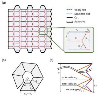
The REBO design (Fig. 1(a)) is an origami bellows. The fold pattern is a tessellation of rectangular units arranged into columns and rows, with the left and right columns glued together to form a tube. Each unit contains a middle crease at an angle from horizontal, as shown in the grey box in Fig. 1(a). When folded, these creases cause each row of the structure to collapse into a -sided right frustum with height and side lengths and on the larger and smaller bases (Fig. 1(b)). We define the angle between the base and side of the layer as the cone angle .
There is a direct relationship between the geometric parameters of the fold pattern and those of the 3-D folded state. In particular, the rotation angle of each trapezoid shown in Fig. 1(b) is . The values of and can then be calculated as
| (1) | ||||
| (2) |
The design has the ability to store potential energy in the bending of the folds and the stretching of the faces, similarly to the multistable “bendy straw” design [27]. Interestingly, by changing the size of the design and geometric parameters such as and , the amount of structural deformation required for the design to bend and compress can be manipulated, thus allowing us to control the stiffness of the design purely through its geometry. When is , the folded state is a flat polygon with little resistance to axial forces. This is because the flat folded configuration relies on torsional stiffness in the folds, which is typically small. As increases, the slope of each layer increases, and REBO cannot be folded flat without deformation of the fold surfaces. In other words, the potential energy of compressing the structure is now stored not only in the folds, but also in the sheet surfaces, making the structure stiffer. Thus by designing , one can generate spring-like structures with variable degree of stiffness.
II-B Effect of Cone Angle on Stiffness
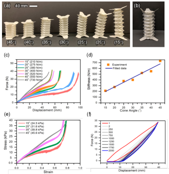
To understand the relation between the cone angle and the stiffness of the REBO, we folded multiple versions of the pattern with variable geometric parameters and conducted compression tests. All samples were folded out of 8 mil thick Durilla synthetics paper with polyester finish (CTI Paper, USA) and used 3M 467MP adhesive transfer tape to glue the left and right sides together as a closed cylinder. The parameters chosen for this study were as follows: , , , , and a total of layers. We tested cone angles between and , with increments of in between. The crease patterns are then generated from a MATLAB script. Fig. 2(a) shows the results of the fabrication. The theoretical rest length of all of these REBO structures should be . However, due to the imperfection of manual folding, the final rest lengths are not equal, and in fact decrease as increase. The true rest lengths were measured and used for the following experiments.
We used an Instron Model 5564 with 100N compression load cell to measure the force required to compress each specimen from its natural length until all the layers were stacked flat and the force exceeded 40N. Each specimen was measured 5 times.
The result of the experiment is shown in Fig. 2(c). The shaded regions show the minimum and maximum force values corresponding to each displacement for the sample. The results show that REBO structure exhibits a Hookean force-displacement curve for well over 2/3 of its total travel. We computed the effective stiffness (elastic constant) as the slope of the linear fit in this region. The sharp increase in stiffness at the end of the curve corresponds to all of the layers coming into contact with each other so that the specimen can be viewed as a solid cylinder. This region should be avoided during application. Fig. 2(d) summarizes the mean effective stiffness for each of the measured samples. A linear fit indicates that the stiffness increases as a roughly affine function of the cone angle , , with . The REBO design was able to achieve a broad range of stiffnesses from .
We computed stress-strain curves for each of the specimens (Fig. 2(e)). Strain was calculated using the real rest length and the stress was the compression force acting on the effective hexagonal area , with the Young’s modulus as the slope of the resulting curve. The results show that the cone angle does indeed have a significant effect beyond simply changing the length of the REBO.
During experiments, we found that the dimensions of the REBO affect the stress-strain profile. For REBOs with the same cone angle , a larger side length and height reduces the Young’s modulus. As a result, a higher is required to achieve a similar profile for a larger-scale model. The scaling study of this REBO structure will be the focus of future work.
II-C Double-Layered Design
| Inner layer () | Outer layer () | Double layer |
|---|---|---|
| () | () | |
| () | () | |
| () | () |
The results show that a maximum stiffness of for the REBO design is achieved at . Above this value, the structure is at risk of buckling irreversibly upon compression. However, higher stiffness can be achieved by arranging multiple REBO structures concentrically, as shown in Fig. 1(c) and 2(b). This parallel spring structure demonstrates additive stiffness and protects against snap-through buckling to the bistable inverted configurations, which were previously demonstrated in other applications [24]. Here, three sets of double layer structure have been fabricated, with the cone angle of the inner and the outer structure to be , , and , respectively. To facilitate the fabrication of the double layered REBO structure, we increased to make room for the inner structure to slide through, then refolded it to enclose it. A compression test was performed before and after the combination and the stiffness of each specimen was measured (see summary of results in Table I). The stiffness of the double layer structure is indeed the sum of the stiffness of the two individual layers with a maximum error of only . It is to our observation that by increasing , the stiffness decreases a little due to the fact that there is more space for the paper to deform.
II-D Repeatability and Energy Loss
Finally, for dynamic robot applications, it is important to understand the energy dissipation and resilience of the REBO design. We therefore experimentally measured the response of a REBO under cyclic loading. The specimen was alternately compressed and released between its original rest length and displacement for 2000 cycles. Each cycle took 12 seconds. The results are shown in Fig. 2(f).
While the first cycle (red) required much higher forces than the rest of the trials, the response of the REBO quickly converged to the blue curve after the second trial, and remained consistent for the rest of the trials. This behavior is consistent with literature in origami mechanics, where the first folding is often an outlier [28] since it plastically deforms the material and changes the structure’s equilibrium state.
For repeated dynamic tasks, we are primarily concerned with the steady-state behaviors, i.e., the blue curve. We observed elastic hysteresis between the tension and compression portions of the tests, suggesting that more energy was required for loading comparing to unloading, and thermal energy was dissipated during this process. The displacement offset after 2000 runs is small compare to the original length, with a maximum of , of the rest length. After 2000 cycles, no physical damage was observed on the specimen and no failure was found on the force-displacement plot.
III Juggling Robot Design
Our characterization shows that stiffness on the order of , the range where energy exchange with loads has been shown to achieve useful aerial-phase compliant-legged running gaits [29], can be easily accessible, and importantly that this performance does not degrade over repeated uses. Armed with the understanding, we integrate the programmable compliance design to legged robots in the form of the “REBO Juggler.” Juggling a weighted ball continuously at a certain height requires a periodic motion and great power, similar to many dynamical locomotion tasks.
III-A Robot Platform
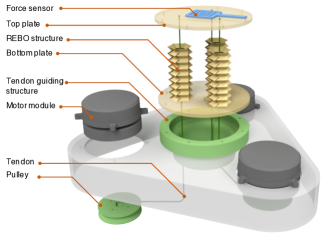
The robot (Fig. 3) consists of four main parts: (a) the compliant REBO body, (b) force transmitting system composed of brushless DC electrical motor modules (Ghost Robotics MNSB01 Sub-Minitaur U8 Motor Module [30]) with tendon (Sufix 832 Advanced Superline Braid) and 3D-printed pulley system, (c) contact detection using force sensor (Ohmite FSR01CE), and (d) a microprocessor (Ghost Robotics MNS043 mainboard [30]) for integrating sensing and control. The compliant body, shown in Fig. 4(a), is composed by three double-layered REBO structures with a stiffness of each. The parameters of the outer layer are , , , , , , and the ones for the inner layer are , , , , , . Each REBO weighs about . Three REBOs were then mounted between the top and bottom acrylic plates and secured using tabs, forming the compliant body that weighs about . The tendon was laced through the structural through-holes of REBO, with one end fixed on the top plate and the other on the pulley mounted on the motor. Rotating the motor compressed or released the REBO, and the speed limitation of the linear motion on REBO was determined by the motor. A force sensor was placed on top of the top plate to detect when an object was in contact with the top plate.
III-B Kinematic Model
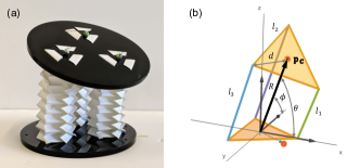
The robot platform can be modeled as two equilateral triangles connected at the corners by three tendons (Fig. 4(b)), where the change of tendon length changes the position and orientation of the top triangle. Let the origin of the model be at the center of the bottom triangle. The top and the bottom triangles have circumcircles of radius . The linear actuator state is defined as , where , , and are the length of the three parallel linear actuators, and , are the length constraints of the actuators. The tendon is attached to a pulley mounted on the motor, where the motor state is defined as , and the mapping from the motor space to the linear actuator space is:
| (3) |
where the index indicates different actuator pairs, is the rest length of REBO, is the radius of the pulley and is the angle of rotation of the corresponding motor.
The position vector of the center of the top triangle is . For this three DOF system, the orientation of the top triangle is coupled with its position, which can be fully described with , where is the length of , is the angle between and the axis, and is the angle between and the axis. The kinematics can found by observing the geometry of the model to be:
| (4) | ||||
| (5) | ||||
| (6) |
The position vector can be described in Cartesian coordinates as
| (7) |
When controlling the robot, the input command to the motor can be found by the inverse map of the kinematics as
| (8) |
IV Kinematic Task: Pointing
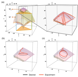
The trajectory of the REBO Juggler’s top plate can be planned within its constrained workspace, and the controlling command of the motor can be found through the inverse map as shown in Eq. (8). The kinematically achievable workspace of the top plate is the image through the kinematic model of the extreme of the length of the tendon and and can be described as . The actuator achievable workspace is a subset of the full workspace , and is limited by the continuous torque of the motor, where its minimum value can be found as , where is the effective stiffness of one REBO. Since this research explores the structure with high stiffness, the achieved compression is small. Fig. 5 shows the image through the kinematic model , with and . The constrained workspace has a volume of .
To demonstrate the mobility of the top plate, we tracked the position of the top plate under varying control inputs using an OptiTrack motion capture system. The first experiment was a open-loop workspace boundary test. It can be seen from Eq. (4) that the boundary of the workspace occurs where two of the linear actuators are at their maximum (or minimum) length and the third changes length. We therefore measured the trajectory of the top plate when each linear actuator was moved between and individually while holding the other constant. The experimental results are shown as the red trajectories in Fig. 5(a), which capture the structure of the simulated workspace, and has a rms error from the predicted boundary. The volume of the convex hull of these trajectories is , which has a error from the predicted volume.
To check the accuracy of the kinematic model, we commanded the top plate of the robot to follow circular trajectories that were generated to lie within the workspace. The top plate was set to follow first a horizontal circle with radius , then a vertical circle with radius , both centered at . Fig. 5(b) and 5(c) show the results of the two experiments. The root mean square errors for the two tracking tests were and , respectively. Fig. 5(c) shows that the real and desired trajectories of the vertical circle deviate closer to the bottom. This is because the actuator needs more torque for greater compression, yet is limited by the motors’ maximum continuous torque. This limitation is expected to be eliminated when we change to a motor with a greater torque or have a higher bandwidth controller.
V Dynamical Task: Vertical Juggling
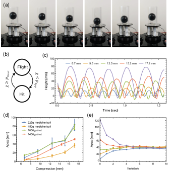
Reflecting the past traditions of the field of dynamical locomotion, the core problem of stable running [31] can be reduced to the problem of stable vertical hopping [32], for which a purely vertical juggle is a representative surrogate [33, 34]. Thus, as a proof-of-concept task, the REBO juggler’s ball, its dynamical ”environment,” is restricted to purely vertical motion by confinement within a tube mounted on the paddle, while the parallel three REBO elements can be viewed as an actively loaded single virtual vertical spring. Since the REBO exhibits elastic hysteresis, the total energy of the ball would be substantially diminished by each encounter with a relaxed paddle, hence additional energy must be pre-loaded into the waiting spring so as to impart at each hit the work needed to keep the ball bouncing. Specifically, to pump energy into the coupled robot-environment system, the motors work on the REBO by pre-compressing it to a fixed position , before the ball lands on the paddle. When the sensing pad detects contact, the REBO then releases the energy into the ball by resetting the set point of the tendon to its rest length . Fig. 6(a) shows a successful juggling period of one of the open-loop experiments presented in this section.
Juggling arises from a hybrid dynamical system comprising two modes: “Flight” and “Hit”, as shown in Fig. 6(b). In the “Flight” mode, the launched ball exhibits a ballistic trajectory governed by the lossless constant gravity system , where and are the mass and the position of the ball, respectively. After the ball’s launch, the juggler quickly resets back to its pre-compressed position. Because the compliant REBO structure has a mass that is negligible (less by at least an order of magnitude) relative to that of the frame or ball, we ignore any REBO dynamics and treat the reset as instantaneous. The “Flight” mode stops when the force sensor on the paddle is triggered by the ball’s contact and the system enters the “Hit” mode. Now, the ball rides down the paddle of the compressing REBO structure, and the whole system can be considered as a mass on a spring. The REBO elastic energy is imparted to the ball’s mass as governed by the dynamics , where is the juggler’s effective stiffness and its damping coefficient. The “Hit” mode ends when the REBO reaches its rest length, whereupon the ball lifts off as reported by the force sensor, the motor re-engages the tendon, and the system re-enters the “Flight” mode.
REBO’s Hookean force-extension curve (Fig. 2(c)) implies that the more it is compressed, the more energy it stores; hence, because it can sustain high forces under load, the juggler injects more energy into the ball in “Hit” mode with greater pre-compression, resulting in higher apex positions. Fig. 6(c) documents this increase in vertical oscillation amplitude for a shot under increasing commanded pre-compression lengths . A slow motion video of 120 fps has been filmed for every trial and the trajectory of the ball was found using “Tracker” (https://physlets.org/tracker/). The result confirms that the more the REBO is pre-compressed, the higher the ball can be juggled.
Fig. 6(d) summarizes the results of repeated (100 juggling cycles each) experiments with several different balls being juggled under different pre-compressed lengths by plotting the mean and standard deviation of measured apex heights. Two shots of mass and were selected because their resilient rigid metal composition yields an approximately elastic collision, presenting a “lossless environment” to the juggler. In contrast, two sand-loaded medicine balls of mass and yield highly inelastic collisions chosen to confront the juggler with a “highly dissipative environment.” It is clear that the average apex height is monotonically increasing with respect to the pre-compression for all the balls. For the same compressive pre-load condition, the heavier balls have a lower apex than the lighter ones as expected if each pair is restored to the same steady energy state. Here, since the medicine balls dissipate more stored energy than the shots, making them harder to juggle, the juggler lofts the ball to roughly the same steady state apex as the shot. We can summarize the energetic properties of the REBO structure with respect to its work on the balls as follows. The energy loaded into the REBO structure by the DC servos’ pre-compression work is for the shot bounced at a height of . Since the “Hit” mode has a typical duration of the REBO delivers a mechanical power output of .
Fig. 6(e) plots the trajectories over the course of the first ten successive collisions (out of hundreds recorded) with the juggler’s paddle of the apex heights of the shot starting from five different initial conditions, all subject to the same pre-compressed REBO length of . Treating the apex height as the coordinate chart for the Poincaré section of this hybrid dynamical system, the plot demonstrates the asymptotic stability of the period one hybrid limit cycle by displaying convergence to the fixed point of the associated Poincaré (or “return”) map [33]. The results suggest the relatively large basin of attraction (set of initial heights that are successfully juggled up or down to the desired steady state apex height) achieved by the juggler consistent with a high power actuator along the lines discussed in [34].
VI Discussion and Future Work
The resilient, tunable stiffness of the lightweight, deformable REBO structure allows us to transfer energy through the 1kg shot at roughly , repeatedly over the course of thousands of hits with very little fatigue, as attested by the highly repeatable asymptotically stable steady state juggling cycles, lofting 1 kg loads to nearly 10 cm heights. Thus, the REBO breaks new ground in the soft robotics literature by transducing energy, which, when distributed across the repeating origami structure, is sufficient to power the task of vertical juggling — an established route to dynamical dexterity in conventional robotics [33]. Indeed, we have begun work to turn the REBO juggler “upside down,” aiming for a power autonomous “soft” hopper capable of lifting its batteries and actuators to comparable apex states. The experiments presented here focus on merely modifying the cone angle for REBOs made of the same materials with the same thicknesses and having the same number of sides and side lengths. Future work yielding a more formal understanding of the REBO’s properties will afford scaling laws that achieve a generalizable tunably compliant design methodology for a broad range of robotics applications.
Acknowledgment
This work is supported in part by the Army Research Office (ARO) under the SLICE Multidisciplinary University Research Initiatives (MURI) Program, award # W911NF1810327. We thank Diego Caporale for technical consultant and Diedra Krieger for administrative support.
References
- [1] M. Buehler and D. E. Koditschek, “Robotics in an intermittent dynamical environment: A prelude to juggling,” in Proc. 26th IEEE Conference on Decision and Control., Dec 1987. [Online]. Available: https://kodlab.seas.upenn.edu/uploads/Kod/BuehlerKoditschek87prelude˙juggling.pdf
- [2] M. Buehler and D. Koditschek, “Analysis of a simplified hopping robot,” in , 1988 IEEE International Conference on Robotics and Automation, 1988. Proceedings, Apr 1988, p. 817–819 vol.2.
- [3] R. R. Burridge, A. A. Rizzi, and D. E. Koditschek, “Toward a systems theory for the composition of dynamically dexterous robot behaviors,” in ROBOTICS RESEARCH-INTERNATIONAL SYMPOSIUM-, vol. 7, 1996, p. 149–161.
- [4] A. Rizzi and D. Koditschek, “An active visual estimator for dexterous manipulation,” Robotics and Automation, IEEE Transactions on, vol. 12, no. 5, p. 697–713, 1996.
- [5] M. Venkadesan, J. Guckenheimer, and F. J. Valero-Cuevas, “Manipulating the edge of instability,” Journal of Biomechanics, vol. 40, no. 8, p. 1653–1661, Jan 2007.
- [6] E. L. Lawrence, I. Fassola, I. Werner, C. Leclercq, and F. J. Valero-Cuevas, “Quantification of dexterity as the dynamical regulation of instabilities: Comparisons across gender, age, and disease,” Frontiers in Neurology, vol. 5, 2014. [Online]. Available: https://www.frontiersin.org/articles/10.3389/fneur.2014.00053/full#B1
- [7] F. J. Valero-Cuevas, N. Smaby, M. Venkadesan, M. Peterson, and T. Wright, “The strength–dexterity test as a measure of dynamic pinch performance,” Journal of Biomechanics, vol. 36, no. 2, p. 265–270, Feb 2003.
- [8] S. Revzen and D. E. Koditschek, “Why we need more degrees of freedom,” Procedia IUTAM, vol. 20, pp. 89–93, 2017.
- [9] I. W. Hunter, J. M. Hollerbach, and J. Ballantyne, “A comparative analysis of actuator technologies for robotics,” Robotics Review, vol. 2, p. 299–342, 1992.
- [10] C. Laschi and M. Cianchetti, “Soft robotics: new perspectives for robot bodyware and control,” Frontiers in bioengineering and biotechnology, vol. 2, p. 3, 2014.
- [11] L. L. Howell, Compliant mechanisms. John Wiley & Sons, 2001.
- [12] A. D. Marchese, C. D. Onal, and D. Rus, “Autonomous soft robotic fish capable of escape maneuvers using fluidic elastomer actuators,” Soft Robotics, vol. 1, no. 1, pp. 75–87, 2014.
- [13] M. T. Tolley, R. F. Shepherd, M. Karpelson, N. W. Bartlett, K. C. Galloway, M. Wehner, R. Nunes, G. M. Whitesides, and R. J. Wood, “An untethered jumping soft robot,” in 2014 IEEE/RSJ International Conference on Intelligent Robots and Systems. IEEE, 2014, pp. 561–566.
- [14] C. D. Onal, R. J. Wood, and D. Rus, “An origami-inspired approach to worm robots,” IEEE/ASME Transactions on Mechatronics, vol. 18, no. 2, pp. 430–438, April 2013.
- [15] B. A. Jones and I. D. Walker, “Kinematics for multisection continuum robots,” IEEE Transactions on Robotics, vol. 22, no. 1, pp. 43–55, 2006.
- [16] W. McMahan, B. A. Jones, and I. D. Walker, “Design and implementation of a multi-section continuum robot: Air-octor,” in Proc. of IEEE/RSJ Intl. Conf. on Intelligent Robots and Systems, 2005, pp. 2578–2585.
- [17] S. Li, J. J. Stampfli, H. J. Xu, E. Malkin, E. V. Diaz, D. Rus, and R. J. Wood, “A vacuum-driven origami “magic-ball” soft gripper,” in 2019 International Conference on Robotics and Automation (ICRA), May 2019, pp. 7401–7408.
- [18] A. M. Hoover, E. Steltz, and R. S. Fearing, “RoACH: An autonomous 2.4 g crawling hexapod robot,” in 2008 IEEE/RSJ International Conference on Intelligent Robots and Systems, 2008, pp. 26–33.
- [19] J. P. Whitney, P. S. Sreetharan, K. Y. Ma, and R. J. Wood, “Pop-up book MEMS,” Journal of Micromechanics and Microengineering, vol. 21, no. 11, p. 115021, 2011.
- [20] R. V. Martinez, C. R. Fish, X. Chen, and G. M. Whitesides, “Elastomeric origami: programmable paper-elastomer composites as pneumatic actuators,” Advanced functional materials, vol. 22, no. 7, pp. 1376–1384, 2012.
- [21] K. Zhang, C. Qiu, and J. S. Dai, “An extensible continuum robot with integrated origami parallel modules,” Journal of Mechanisms and Robotics, vol. 8, no. 3, p. 031010, 2016.
- [22] J. Santoso, E. H. Skorina, M. Luo, R. Yan, and C. D. Onal, “Design and analysis of an origami continuum manipulation module with torsional strength,” in 2017 IEEE/RSJ International Conference on Intelligent Robots and Systems (IROS), Sep. 2017, pp. 2098–2104.
- [23] A. Johnson and D. Koditschek, “Legged self-manipulation,” IEEE Access, vol. 1, p. 310–334, 2013.
- [24] H. Yuan, J. H. Pikul, and C. Sung, “Programmable 3-d surfaces using origami tessellations,” in 7th International Meeting on Origami in Science, Mathematics, and Education, 2018, pp. 893–906.
- [25] A. Reid, F. Lechenault, S. Rica, and M. Adda-Bedia, “Geometry and design of origami bellows with tunable response,” Physical Review E, vol. 95, no. 1, p. 013002, 2017.
- [26] E. T. Filipov, T. Tachi, and G. H. Paulino, “Origami tubes assembled into stiff, yet reconfigurable structures and metamaterials,” Proceedings of the National Academy of Sciences, vol. 112, no. 40, pp. 12 321–12 326, 2015.
- [27] N. P. Bende, T. Yu, N. A. Corbin, M. A. Dias, C. D. Santangelo, J. A. Hanna, and R. C. Hayward, “Overcurvature induced multistability of linked conical frusta: how a ‘bendy straw’holds its shape,” Soft matter, vol. 14, no. 42, pp. 8636–8642, 2018.
- [28] C. Qiu, V. Aminzadeh, and J. S. Dai, “Kinematic analysis and stiffness validation of origami cartons,” Journal of Mechanical Design, vol. 135, no. 11, p. 111004, 2013.
- [29] K. C. Galloway, J. E. Clark, and D. E. Koditschek, “Design of a multi-directional variable stiffness leg for dynamic running,” in ASME 2007 International Mechanical Engineering Congress and Exposition. American Society of Mechanical Engineers, 2007, pp. 73–80.
- [30] “Ghost Robotics,” https://www.ghostrobotics.io.
- [31] M. H. Raibert, Legged robots that balance. MIT press, 1986.
- [32] ——, “Dynamic stability and resonance in a legged hopping machine,” in Conference on Theory and Practice of Robots and Manipulators, IFToMM, 1983, pp. 352–367.
- [33] M. Buehler, D. E. Koditschek, and P. Kindlmann, “A simple juggling robot: Theory and experimentation,” in Experimental Robotics I. Springer, 1990, pp. 35–73.
- [34] D. E. Koditschek and M. Buehler, “Analysis of a simplified hopping robot,” The International Journal of Robotics Research, vol. 10, no. 6, pp. 587–605, 1991.