Crystal-based intensive gamma-ray light sources
Abstract
We discuss design and practical realization of novel gamma-ray Crystal-based Light Sources (CLS) that can be constructed through exposure of oriented crystals (linear, bent, periodically bent) to beams of ultrarelativistic charged particles. In an exemplary case study, we estimate brilliance of radiation emitted in a Crystalline Undulator (CU) LS by available positron beams. Intensity of CU radiation in the photon energy range MeV, which is inaccessible to conventional synchrotrons, undulators and XFELs, greatly exceeds that of laser-Compton scattering LSs and can be higher than predicted in the Gamma Factory proposal to CERN. Brilliance of CU-LSs can be boosted by up to 8 orders of magnitude through the process of superradiance by a pre-bunched beam. Construction of novel CLSs is a challenging task which constitutes a highly interdisciplinary field entangling a broad range of correlated activities. CLSs provide a low-cost alternative to conventional LSs and have enormous number of applications.
1 Introduction
The development of light sources (LS) for wavelengths well below 1 angstrom (corresponding photon energies keV) is a challenging goal of modern physics. Sub-angstrom wavelength powerful spontaneous and, especially, coherent radiation will have many applications in the basic sciences, technology and medicine. They may have a revolutionary impact on nuclear and solid-state physics, as well as on the life sciences. At present, several X-ray Free-Electron-Laser (XFEL) sources are operating (European XFEL, FERMI, LCLS, SACLA, PAL-XFEL) or planned (SwissFEL) for X-rays down to Å [2, 1, 3, 6, 4, 5]. However, no laser system has yet been commissioned for lower wavelengths due to the limitations of permanent magnet and accelerator technologies. Modern synchrotron facilities, such as APS, SPring-8, PETRA III, ESRF [7, 8], provide radiation of shorter wavelengths but of much less intensity which falls off very rapidly as decreases.
Therefore, to create a powerful LS in the range well below 1 Å, i.e. in the hard X and gamma ray band, one has consider new approaches and technologies.
In this article we discuss possibilities and perspectives for designing and practical realization of novel gamma-ray Crystal-based LSs (CLS) operating at photon energies keV and above that can be constructed through exposure of oriented crystals (linear, bent and periodically bent crystals) to beams of ultrarelativistic charged particles. CLSs include Channeling Radiation (ChR) emitters, crystalline synchrotron radiation emitters, crystalline Bremsstrahlung radiation emitters, Crystalline Undulators (CU) and stacks of CUs. This interdisciplinary research field combines theory, computational modeling, beam manipulation, design, manufacture and experimental verification of high-quality crystalline samples and subsequent characterization of their emitted radiation as novel LSs. In an exemplary case study, we estimate the characteristics (brilliance, intensity) of radiation emitted in CU-LS by positron beams available at present. It is demonstrated that peak brilliance of the CU Radiation (CUR) at MeV is comparable to or even higher than that achievable in conventional synchrotrons but for much lower photon energies. Intensity of radiation from CU-LSs greatly exceeds that available in the laser-Compton scattering LSs and can be made higher than predicted in the Gamma Factory proposal to CERN [10, 9]. The brilliance can be boosted by orders of magnitude through the process of superradiance by a pre-bunched beam. We show that brilliance of superradiant CUR can be comparable with the values achievable at the current XFEL facilities which operate in much lower photon energy range.
CLSs can generate radiation in the photon energy range where the technologies based on the charged particles motion in the fields of permanent magnets become inefficient or incapable. The limitations of conventional LS is overcome by exploiting very strong crystalline fields that can be as high V/cm, which is equivalent to a magnetic field of 3000 Tesla whilst modern superconducting magnets provide 1-10 Tesla [11]. The orientation of a crystal along the beam enhances significantly the strength of the particles interaction with the crystal due to strongly correlated scattering from lattice atoms. This allows for the guided motion of particles through crystals of different geometry and for the enhancement of radiation.
Examples of CLSs are shown in Figure 1. The synchrotron radiation is emitted by ultra-relativistic projectiles propagating in the channeling regime through a bent crystal, panel a). A CU, panel b), contains a periodically bent crystal and a beam of channeling particles which emit CUR following the periodicity of the bending [12, 13, 14]. A CU-based LS can generate photons of keV - GeV range (corresponding to from 0.1 to Å). Under certain conditions, CU can become a source of the coherent light within the range Å [14, 15, 16]. An LS based on a stack of CUs is shown in panel c) [17].
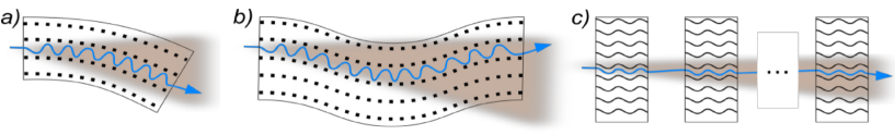
Practical realization of CLSs often relies on the channeling effect. The basic phenomenon of channeling is in a large distance which a projectile particle penetrates moving along a crystallographic plane or axis and experiencing collective action of the electrostatic fields of the lattice atoms [18]. A typical distance covered by a particle before it leaves the channeling mode due to uncorrelated collisions is called the dechanneling length, . It depends on the type of a crystal and its orientation, on the type of channeling motion, planar or axial, and on the projectile energy and charge. In the planar regime, positrons channel in between two adjacent planes whereas electrons propagate in the vicinity of a plane thus experiencing more frequent collisions. As a result, for electrons is much less than for positrons. To ensure enhancement of the emitted radiation due to the dechanneling effect, the crystal length must be chosen as [12, 13, 14].
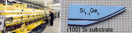
The motion of a projectile and the radiation emission in bent and periodically bent crystals are similar to those in magnet-based synchrotrons and undulators. The main difference is that in the latter the particles and photons move in vacuum whereas in crystals they propagate in medium, thus leading to a number of limitations for the crystal length, bending curvature, and beam energy. However, the crystalline fields are so strong that they steer ultra-relativistic particles more effectively than the most advanced magnets. Strong fields bring bending radius in bent crystals down to the cm range and bending period in periodically bent crystals to the hundred or even ten microns range. These values are orders of magnitude smaller than those achievable with magnets [4]. As a result, the radiators can be miniaturized thus lowering dramatically the cost of CLSs as compared to that of conventional LSs. Figure 2 matches the magnetic undulator for the European XFEL with the CU manufactured in University of Aarhus and used in recent experiments [19].
Modern accelerator facilities make available intensive electron and positron beams of high energies, from the sub-GeV up to hundreds of GeV. These energies combined with large bending curvature achievable in crystals provide a possibility to consider novel CLSs of the synchrotron type (continuous spectrum radiation) and of the undulator type (monochromatic radiation) of the energy range up to tens of GeV. Manufacture of high quality bent and periodically bent crystals is at the edge of current technologies.
2 Exemplary crystal-based LSs
A number of theoretical and experimental studies of the channeling phenomenon in oriented linear crystals have been carried out (see, e.g., a review [21]). A channeling particle emits intensive ChR, which was predicted theoretically [22] and shortly after observed experimentally [23]. Since then there has been extensive theoretical and experimental investigation of ChR. The energy of emitted photons scales with the beam energy as and thus can be varied by changing the latter. For example, by propagating electrons of moderate energies, MeV, through a linear crystal it is possible to generate ChR with photon energy keV [24, 25]. This range can be achieved in magnetic undulators but with much higher beam energy. High-quality electron beams of (tunable) energies within the tens of MeV range are available at many facilities. Hence, it has become possible to consider ChR from linear crystals as a new powerful LS in the X-ray range [24].
In the gamma-range, ChR can be emitted by higher energy MeV beams. However, modern accelerator facilities operate at a fixed value of (or, at several fixed values) [26, 27, 28]. This narrows the options for tuning the ChR parameters, in particular, the wavelength. Hence, the corresponding CLS lack the tunability option. From this viewpoint, the use of bent and, especially, periodically bent crystals can become an alternative as they provide tunable emission in the hard X- and gamma-ray range.
Strong crystalline fields give rise to channeling in a bent crystal. Since its prediction [29] and experimental support [30], the idea to deflect high-energy beams of charged particles by means of bent crystals has attracted a lot of attention [31, 21]. The experiments have been carried with ultra-relativistic protons, ions, positrons, electrons, -mesons [32, 33, 34, 19, 35]. Steering of highly energetic electrons and positrons in bent crystals with small bending radius gives rise to intensive synchrotron radiation with MeV. The parameters of radiation can be tuned by varying within the range cm [36, 37].
Even more tunable is a CU-LS. In this system CUR and ChR are emitted in distinctly different photon energy ranges so that CUR is not affected by ChR. The intensity, photon energy and line-width of CUR can be varied and tuned by changing , bending amplitude and period , type of crystal, its length and detector aperture [16].
Since introducing the concept of CU, major theoretical studies have been devoted to the large-amplitude large-period bending [12, 13, 14]. In this regime, a projectile follows the shape of periodically bent planes. CUR is emitted at the frequencies well below those of ChR, . By varying , , and the crystal length one can tune the CUR peaks positions and intensities. Small-amplitude small-period regime, which implies and less than period of channeling oscillations [38, 39, 40, 41, 42]. This scheme allows emission of photons of the higher energies, , makes feasible construction of a CLS which radiates in the GeV photon energy range [43].
Initially, the CU feasibility was justified for positrons [12, 13]. Positrons channel over larger distances passing larger number of bending periods and, thus, increasing the CUR intensity. Experiments carried out so far to detect CUR from positrons have not been successful due insufficient quality of periodic bending, large beam divergence and high level of the background bremsstrahlung radiation [45, 44]. The feasibility of CU for electrons was also proven [46] but it was indicated that to obtain better CUR signal high-energy (GeV and above) electron beams are preferable. The CUR signal was detected in the experiments with electron beam of much lower energies at the Mainz Microtron [47, 48]. The radiation excess due to CUR was detected although it was not as intense as expected. In part, this discrepancy can be attributed to insufficient quality of the crystalline lattice although this issue has to be investigated in more detail. Also the beam energy used was low (sub-GeV range) and as a consequence photon energies, as well as the choice of particles (electrons) were not optimal.
3 Practical realization of CU
In the current paper a case study of a tunable CU-based LS is presented. Therefore below we focus on the methods which allow one to produce undulating crystal samples.
The feasibility of the CU concept was verified theoretically in Refs. [12, 13, 14, 49] where essential conditions and limitations which must be met were formulated. These papers boosted theoretical and experimental investigation of the CU and CUR phenomena worldwide, so that nowadays these topics represent a new and very rich field of research.
Theoretical and experimental studies of the CU and CUR phenomena has ascertained the importance of the high quality of the undulator material needed to achieve strong effects in the emission spectra. Up to now, several methods to create periodically bent crystalline structures have been proposed and/or realized.
Figure 3 provides schematic illustration of the ranges of and within which the emission of intensive CUR is feasible. Shadowed areas mark the ranges currently achievable by different technologies.
Several approaches have been applied to produce static bending. The greenish area marks the area achievable by means of technologies based on surface deformations. These include mechanical scratching [50], laser ablation technique [51], grooving method [52, 53], tensile/compressive strips deposition [52, 54, 55], ion implantation [56]. The most recent techniques proposed is based on sandblasting one of the major sides of a crystal to produce an amorphized layer capable of keeping the sample bent [57]. Another technique, which is under consideration in for manufacturing periodically bent silicon and germanium crystals, is pulsed laser melting processing that produces localized and high-quality stressing alloys on the crystal surface. This technology is used in semiconductor processing to introduce foreign atoms in crystalline lattices [58]. Currently, by means of the surface deformation methods the periodically bent crystals with large period, microns, can be produced.
To decrease the period one can rely on production of graded composition strained layers in an epitaxially grown Si1-xGex superlattice [59, 60]. Both silicon and germanium crystals have the diamond structure with close lattice constants. Replacement of a fraction of Si atoms with Ge atoms leads to bending crystalline directions. By means of this method sets of periodically bent crystals have been produced and used in channeling experiments [61]. A similar effect can be achieved by graded doping during synthesis to produce diamond superlattice [62]. Both boron and nitrogen are soluble in diamond, however, higher concentrations of boron can be achieved before extended defects appear [62, 63]. The advantage of a diamond crystal is radiation hardness allowing it to maintain the lattice integrity in the environment of very intensive beams [21]. The grey area in 3 marks the ranges of parameters achievable by means of crystal growing.
The bluish area indicates the range of parameters achievable by means of another method, realization of which is although still pending, based on propagation of a transverse acoustic wave in a crystal [16].
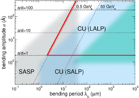
In a Crystalline Undulator (CU), a projectile’s trajectory follows the profile of periodic bending. This is possible when the electrostatic crystalline field exceeds the centrifugal force acting on the projectile. This condition, which entangles bending amplitude and period, the projectile’s energy and the crystal field strength, implies that the bending parameter is less than one, see Eq. (5). Two sloping dashed lines in Fig. 3 show the dependences corresponding to the extreme value for and 50 GeV projectiles. For each energy, the CU is feasible in the domain lying to the right from the line. In this domain, periodic bending is characterized by a Large Period (LP), which implies (i) , and (ii) greatly exceeds the period of channeling oscillations. The horizontal line ( stands for the interplanar distance) divides the CU domain into two parts: the Large-Amplitude (LA), , and the Small-Amplitude (SA), , regions. Larger amplitudes are more favourable from the viewpoint of achieving higher intensities of CUR. The red lines delineate the domain where the LALP periodic bending can be considered.
Another regime of periodic bending, Small-Amplitude Short-Period (SASP), can be realized in the domain and micron (these values of are much smaller that channeling periods of projectiles with GeV). In the SASP regime, in contrast to the channeling in a CU, channeling particles do not follow the short-period bent planes but experience regular jitter-type modulations of their trajectories which lead to the emission of high-energy radiation.
As mentioned, dynamic bending can be achieved by propagating a transverse acoustic wave along a particular crystallographic direction [65, 64, 12, 13, 66, 67, 68]. This can be achieved, for example, by placing a piezo sample atop the crystal and generating radio frequencies to excite the oscillations. The advantage of this method is in its flexibility: the bending amplitude and period can be changed by varying the wave intensity and frequency [12, 13]. Although the applicability of this method has not yet been checked experimentally, we note that a number of experiments has been carried out on the stimulation of ChR by acoustic waves excited in piezoelectric crystals [69].
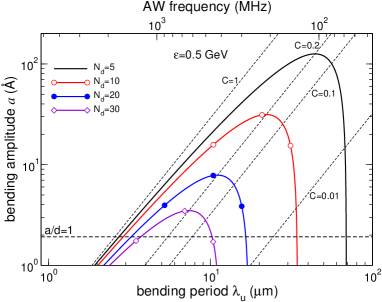
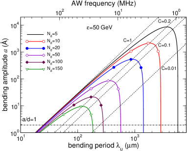
Figure 4 allows one to estimate the acoustic wave frequencies needed to achieve the LALP periodic bending of the silicon(110) planes. The diagonal dashed lines correspond to the dependences obtained for several values (as indicated) of the bending parameter . The CU cannot be realized in the domain lying to the left from the line . The solid curves present the dependences calculated for the fixed values (indicated in the legends) of the number of undulator periods within the dechanneling length , Eq. (8). It is seen that the values microns correspond to the frequencies MHz, which are achievable experimentally ( cm/s is the speed of sound) [69, 70, 71].
4 CU-LS versus state-of-the-art LS
In this section, we present quantitative estimates for the CUR brilliance using the parameters of high-energy positron beams either available at present or planned to be commissioned in near future (see Table 1 in A). We demonstrate that by means of CU-LS, which operates in the LALP regime, one can achieve much higher photon yield as compared to the values achievable in modern LS facilities operating in the gamma-ray range, keV.
The relevant modern facilities are synchrotrons and undulators based on the action of magnetic field.222Fore the sake of comparison we also match our data to the brilliance available at the XFEL facilities for much lower energy of the emitted radiation. Another type of modern LS, which does not utilize magnets, is based on the Compton scattering process [72]. In this process, a low-energy (eV) laser photon backscatters from an ultra-relativistic electron thus acquiring increase in the energy proportional to the squared Lorentz factor . This method has been used for producing gamma-rays in a broad, keV – MeV, energy range [73, 74].
The Compton scattering also occurs if the scatterer is an atomic (ionic) electron which moves being bound to a nucleus. This phenomenon is behind the Gamma Factory proposal for CERN [10, 9] that implies using a beam of ultra-relativistic ions in the backscattering process. In this case, an ionic electron is resonantly excited by absorbing a laser photon. The subsequent radiative de-excitation produces a gamma-photon.
4.1 Brilliance and intensity of CUR
The radiometric unit frequently used to compare different LS is brilliance, . It is defined in terms of the number of photons of frequency within the interval emitted in the cone per unit time interval, unit source area, unit solid angle and per a bandwidth (BW) [75, 77, 76]. To calculate this quantity is it necessary to know the beam electric current , transverse sizes and angular divergences as well as the divergence angle of the radiation and the ’size’ of the photon beam. Explicit expression for measured in reads [78]
| (1) |
where is the elementary charge. The quantities are the total emittance of the photon source in the transverse directions with and being the ‘apparent’ source size calculated in the diffraction limit [79]. In (1) are measured in millimeters, – in milliradians.
The product on the right-hand side of Eq. (1), represents the number of photons per second (intensity) emitted in the cone and frequency interval (see Eq. (2) in Section B). Using the peak value of the current, , one calculates the peak brilliance, .
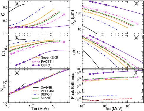
Let us compare the brilliance of CUR with that available at modern synchrotron facilities. Figure 5 presents the peak brilliance calculated for positron-based diamond(110) and Si(110) CUs and that for several synchrotrons. The CUR curves refer to the optimal parameters of CU (see B), i.e. those which ensure the highest values of of CUR for each positron beam indicated.
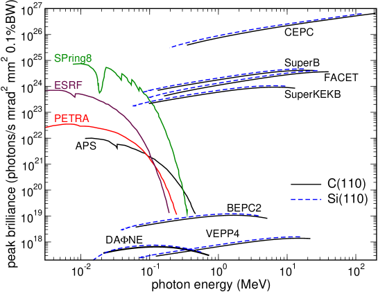
To be noted is that for the well-collimated intensive beams with small transverse sizes (SuperB, FACET, SuperKEK, CEPC) the peak brilliance of CUR in the photon energy range from keV to MeV (the corresponding wavelengths vary from down to Å) is comparable to (the case of SuperB, FACET and SuperKEK beams) or even higher (CEPC beam) than that achievable in conventional LS for much lower photon energies.
We stress that the values of bending amplitude and periods, which maximize the CUR brilliance over broad range of photon energies, are accessible by means of modern technologies (compare Figs. 8 & 9 with Figs. 3 & 4 in A).
The Gamma Factory proposal for CERN discusses a concept of the LS based on the resonant absorption of laser photons by the ultra-relativistic ions [10, 9]. It is expected that the intensity of the LS will be orders of magnitude higher that the presently operating LS aiming at the values of photons/s in the gamma-ray domain MeV. To this end, it is instructive to compare the intensity of CUR with the quoted value as well as with the intensities currently achievable by means of the LS based on laser-Compton scattering from electron beam [73].
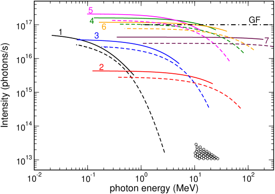
Figure 6 presents the peak intensities, , of the first (solid lines) and third (dashed lines) harmonics of CUR from diamond(110)-based CU with the optimized parameters (see Fig. 9 in B). Different curves correspond to different positron beams as specified in the caption. Most of the curves presented show orders of magnitude higher intensities in the photon energy range one to tens of MeV than that from the laser-Compton scattering LS (open circles). Within the same photon energy interval the CUR intensity can be comparable with or even higher (see the curves for the SuperB, SuperKEK and FACET-II beams) than the value predicted in the Gamma Factory proposal (marked with the horizontal dash-dotted line).
4.2 Brilliance of superradiant CUR
The radiation emitted in an undulator is coherent (at the harmonics frequencies) with respect to the number of periods, , but not with respect to the emitters since the positions of the beam particles are not correlated. As a result, the intensity of of radiation emitted in a certain direction is proportional to and to the number of particles, (the subscript ‘inc’ stands for ‘incoherent’). In conventional undulators, is on the level of [75], therefore, the enhancement due to the factor is large making undulators a powerful source of spontaneous radiation. However, the incoherence with respect to the number of the radiating particles causes a moderate (linear) increase in the radiated energy with the beam density.
More powerful and coherent radiation will be emitted by a beam in which position of the particles is modulated in the longitudinal direction with the period equal to integer multiple to the radiation wavelength . In this case, the electromagnetic waves emitted by different particles have approximately the same phase. Therefore, the amplitude of the emitted radiation is a coherent sum of the individual waves, so that the intensity becomes proportional to the number of particles squared, [80]. Thus, the increase in the photon yield due to the beam pre-bunching (other terms used are ‘bunching’ [5] or ‘microbunching’ [6]) can reach orders of magnitudes relative to radiation by a non-modulated beam of the same density (see the data on in Table 1 in A). Following Ref. [81] we use the term ’superradiant’ to designate the coherent emission by a pre-bunched beam of particles.
In what follows we assume that the beam is fully modulated at the crystal entrance. The description on the methods of preparation of a pre-bunched beam with the parameters needed to amplify CUR one finds in [15] and in Section 8.5 in Ref. [16].
For a pre-bunched beam, the intensity is sensitive not only to the shape of the trajectory but also to the relative positions of the particles along the undulator axis. In the course of beam propagation through the crystal these positions become random due to both the collisions with crystal atoms and the non-similarity of the channeling trajectories for different particles [82]. This leads to the beam demodulation and, as a result, to the loss of the superradiance effect.
For an unmodulated beam, the CU length is limited mainly by the dechanneling process. For a pre-bunched the demodulation becomes the phenomenon which imposes most restrictions on the parameters of a CU. In Ref. [82] the demodulation length, , was introduced to quantify the spatial scale at which a modulated beam becomes demodulated. To preserve the modulation and to maintain the coherence of radiation the crystal length must be less than (see C where essential details are summarized).
Quantitative analysis and numerical data on the parameters of a CU which maximize the brilliance of CUR in presence of the demodulation process is presented in Section D. These data have been used to calculate the peak brilliance of the superradiant CUR.
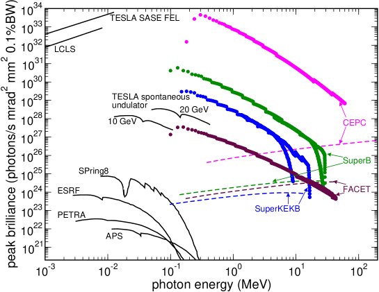
Figure 7 illustrates a boost in peak brilliance due to the beam modulation. Thick curves correspond to superradiant CUR calculated for fully modulated positron beams (as indicated) propagating in the channeling mode through diamond(110)-based CU. In the photon energy range MeV the brilliance of superradiant CUR by orders of magnitudes (up to 8 orders in the case of CEPC) exceeds that of the spontaneous CUR (dash-dotted curves) emitted by the random beams. Remarkable feature is that the superradiant CUR brilliance can not only be much higher that the spontaneous emission from the state-of-the-art magnetic undulator (see the curves for the TESLA undulator) but also be comparable with the values achievable at the XFEL facilities (LCLC (Stanford) and TESLA SASE FEL) which operate in much lower photon energy range.
5 Discussion
Construction of novel CLSs is an extremely challenging task which constitutes a highly interdisciplinary field. To accomplish this task, a broad collaboration is needed of research groups with different but mutually complementary expertise, such as material science, nanotechnology, particle beam and accelerator physics, radiation physics, X-ray diffraction imaging, acoustics, solid state physics, structure determination, advanced computational modeling methods and algorithms, high-performance computing as well as industries specializing in manufacturing of crystalline structures and in design and construction of complete accelerator systems.
As a first step towards achieving the major breakthrough in the field, one can focus on practical realization of the CLS idea, i.e. elaboration of the key theoretical, experimental and technological aspects, demonstration of the device functionality and setting up of standards for the novel technology for construction of the CLSs aiming at their mass production in the future. Realization of this program implies a broad range of correlated and entangles activities including (i) Fabrication of linear, bent and periodically bent crystalline structures with lattice quality necessary for delivering pre-defined bending parameters within the ranges indicated in Figure 3 in A; (ii) Advanced control of the lattice quality by means of the highest quality non-destructive X-ray diffraction techniques. The same techniques to be applied to detect possible structural modification following particle irradiation; (iii) Validation of functionality of the manufactured structures through experiments with high-quality (low energy spread, low emittance, high particle density and current) beams of ultra-relativistic electrons and positrons with GeV, including an authoritative study of the structure sustainability with respect to beam intensity, as well as explicit experimental characterization of the emission spectra; (iv) Advance in computational and numerical methods for multiscale modeling of nanostructured materials with extremely high, reliable levels of prediction (from atomistic to mesoscopic scale), of particle propagation, of irradiation-induced solid state effects, and for calculation of spectral-angular distribution of emitted radiation and for modeling [83]. Ultimately, this will enable better experimental planning and minimisation of experimental costs. The knowledge gained the studies (i)-(v) will provide CLSs prototypes and a roadmap for practical implementation by CLS system manufacturers and accelerator laboratories/users worldwide.
Sub-angstrom wavelength powerful and tunable CLSs will have a broad range of exciting potential applications.
A micron-sized narrow photon beam may be used in cancer therapy. This would greatly improve the precision and effectiveness of the therapy for the destruction of tumour by collimated radiation. Furthermore, it would allow delicate operations to be performed in close vicinity of vital organs. Taking into account the experience gained to date in the field of radio-therapy, one can expect that practical manipulations with micro-sized beams will become active soon after the novel LSs become available.
Gamma-rays induce nuclear reactions by photo-transmutation. For instance, in the experiment of Ref. [84] a long-lived isotope was converted into a short-lived one by irradiation with a gamma-ray bremsstrahlung pulse. However, the intensity of bremsstrahlung is orders of magnitudes less than of CUR. Moreover, to increase the effectiveness of the photo-transmutation process is it desirable to use photons whose energy is in resonance with the transition energies in the irradiated nucleus [73]. By varying the CU parameters one can tune the energy of CUR to values needed to induce the transmutation process in various isotopes. This opens the possibility for a novel technology for disposing of nuclear waste. Photo-transmutation can also be used to produce medical isotopes. Another possible application of the CU-LSs concerns photo-induced nuclear fission when a heavy nucleus is split into two or more fragments due to the irradiation with gamma-quanta whose energy is tuned to match the transition energy between the nuclear states. This process can be used in a new type of nuclear reactor – the photo-nuclear reactor. The production of Positron Emission Tomography (PET) isotopes will be very favourable application, exploiting the reaction in the region of the giant dipole resonance (typically 20-40 MeV). The PET isotopes can be used directly for medial PET and for Positron Emission Particle Tracking experiments. Powerful monochromatic radiation within the MeV range can be used as an alternative source for producing beams of MeV protons by focusing a photon pulse on to a solid target [84, 85]. Such protons can induce nuclear reactions in materials producing, in particular, light isotopes which serve as positron emitters to be used in PET. Irradiation by hard X-ray strongly decreases the effects of natural surface tension of water [86]. The possibility to tune the surface tension by the irradiation can be exploited to study the many phenomena affected by this parameter in physics, chemistry, and biology such as, for example, the tendency of oil and water to segregate.
6 Conclusion
The exemplary case study of a tunable CU-based LS considered in the paper has demonstrated that peak brilliance of CUR emitted in the photon energy range keV up to MeV by currently available (or planned to be available in near future) positron beams channeling in periodically bent crystals is comparable to or even higher than that achievable in conventional synchrotrons in the much lower photon energy range. Intensity of CUR greatly exceeds the values provided by LSs based on Compton scattering and can be made higher than the values predicted in the Gamma Factory proposal in CERN. By propagating a pre-bunched beam the brilliance in the energy range keV up to MeV can be boosted by orders of magnitude reaching the values of spontaneous emission from the state-of-the-art magnetic undulators and being comparable with the values achievable at the XFEL facilities which operate in much lower photon energy range. Important is that by tuning the bending amplitude and period one can maximize brilliance for given parameters of a positron beam and/or chosen type of a crystalline medium. Last but not least, it is worth to mention that the size and the cost of CLSs are orders of magnitude less than that of modern LSs based on the permanent magnets. This opens many practical possibilities for the efficient generation of gamma-rays with various intensities and in various ranges of wavelength by means of the CLSs on the existing and newly constructed beam-lines.
Though we expect that, as a rule, the highest values of brilliance can be reached in CU-based LSs (or, in those based on stacks of CUs) the analysis similar to the one presented can be carried out for other types of CLSs based on linear and bent crystals. This will allow one to make an optimal choice of the crystalline target and the CLS type to be used in a particular experimental environment or/and to tune the parameters of the emitted radiation matching them to the needs of a particular application.
The case study presented has been focused on the positron beams, which have a clear advantage since the dechanneling length of positrons is order of magnitude larger than that of electrons of the same energy. This allows one to use thicker crystals in channeling experiments with positrons thus enhancing the photon yield. Nevertheless, experimental studies of CLSs with electron beams are worth to be carried out. Indeed, high-quality electron beams of energies starting from sub-GeV range and onward are more available than their positron counterparts. Therefore, these laboratories provide more options for the design, assembly and practical implementation of a full suite of correlated experimental facilities needed for operational realization and exploitation of the novel CLSs. In this connection we note that in the course of channeling experiments at the Mainz Microtron facility with MeV electrons propagating in various CUs, which have been carried out over the last decade within the frameworks of several EU-supported collaborative projects (FP6-PECU, FP7-CUTE, H2020-PEARL), a unique experience has been gained. This experience has ascertained that the fundamental importance of the quality of periodically bent crystals, which, in turn is based on the cutting-edge technologies used to manufacture the crystalline structures, of modern techniques for non-destructive characterization of the samples, of the necessity of using advanced computational methods for numerical modeling of a variety of phenomena involved. On the basis of this experience the bottlenecks on the way to practical realization of the CLSs concept have been established.
To quantify the scale of the impact within Europe and worldwide which the development of radically novel CLSs might have, we can draw historical parallels with synchrotrons, optical lasers and FELs. In each of these technologies there was a significant time lag between the formulation of a pioneering idea, its practical realization and follow-up industrial exploitation. However, each of these inventions has subsequently launched multi-billion dollar industries. The implementation of CLS, operating in the photon energy range up to hundreds of MeV, is expected to lead to a similar advance and CLSs have the potential to become the new synchrotrons and lasers of the mid to late 21st century, stimulating many applications in basic sciences, technology and medicine. The development of CLS will therefore herald a new age in physics, chemistry and biology.
Appendix A Beam Parameters
The data on positron and electron beams energy , bunch length , number of particles per bunch , beam sizes and divergences (the subscripts refer to the horizontal and vertical dimensions, respectively), volume density , and peak current are summarized in Table 1. The table compiles the data for the following facilities: VEPP4M (Russia), BEPCII (China), DANE (Italy), SuperKEKB (Japan) [26], SLAC (the FACET-II beams, Ref. [87]), SuperB (Italy) [88], and CEPC (China) [28]. Note that the SuperB data are absent in the latest review by Particle Data Group [26] since its construction was canceled [89].
| Facility | VEPP4M | BEPCII | DANE | SuperKEKB | SuperB | FACET-II | CEPC |
| Ref. | [26] | [26] | [26] | [26] | [88, 89] | [87] | [28] |
| (GeV) | 6 | 1.9-2.3 | 0.51 | p: 4 | p: 6.7 | 10 | 45.5 |
| e: 7 | e: 4.2 | ||||||
| 15 | 3.8 | p: 2.1 | p: 9.04 | p: 6.5 | p: 0.375 | 8 | |
| (units 1010) | e: 3.2 | e: 6.53 | e: 5.1 | e: 0.438 | |||
| (cm) | 5 | 1.2 | 1-2 | p: 0.6 | 0.5 | p: 0.00076 | 0.85 |
| e: 0.5 | e: 0.00011 | ||||||
| (m) | 1000 | 347 | 260 | p: 10 | 8 | p: 10.1 | 6 |
| e: 11 | 8 | e: 5.5 | |||||
| (m) | 30 | 4.5 | 4.8 | p: 0.048 | 0.04 | p: 7.3 | 0.04 |
| e: 0.062 | e: 5.9 | ||||||
| (mrad) | 0.2 | 0.35 | 1 | p: 0.32 | p: 0.250 | p: 0.178 | 0.03 |
| e: 0.42 | e: 0.313 | e: 0.073 | |||||
| (mrad) | 0.67 | 0.35 | 0.54 | p: 0.18 | p: 0.125 | p: 0.044 | 0.04 |
| e: 0.21 | e: 0.150 | e: 0.044 | |||||
| (A) | 144 | 152 | p: 50-100 | p: 723 | p: 624 | p: 12.1 | 452 |
| e: 77-154 | e: 627 | e: 490 | e: 75.5 | ||||
| (cm-3) | 3.2 | 65 | p: 54 | p: | p: | p: | |
| e: 82 | e: | e: | e: |
Appendix B Optimal Length of a CU
With account for the dechanneling and the photon attenuation, the number of photons of the frequency within the interval emitted in the forward direction within the cone by a projectile in a CU is given by the following expression (see Refs. [90, 16] for the details):
| (2) |
where , is the Bessel function and is the undulator parameter. The subscript enumerates the harmonics of CUR. The frequency of the -th harmonic is expressed in terms of the fundamental harmonic given by
| (3) |
The quantity stands for the channel acceptance, which is defined as a fraction of the incident particles captured into the channeling mode at the crystal entrance (another term used is surface transmission, see e.g. Ref. [91]).
Apart from the factor , the difference between (2) and the formula for an ideal undulator (see, e.g., [78]) is that the number of undulator periods , which enters the latter, is substituted with the effective number of periods, , which depends on the number of periods within the dechanneling length, , and on the ratios and where denotes the dechanneling length and is the photon attenuation length. The effective number of periods is given by [90, 16]:
| (4) |
In the limit , i.e. when the dechanneling and the attenuation are neglected, , as it must be in the case of an ideal undulator. In this case one can, in principle, increase infinitely the number of periods by considering larger values of the undulator length . This will lead to the increase of the number of photons and the brilliance since these quantities are proportional to . The limitations on the values of and are mainly of a technological nature.
The situation is different for a CU, where the number of channeling particles and the number of photons, which can emerge from the crystal, decrease with the growth of . It is seen from (4), that in the limit the parameters and also become infinitely large leading to . This result is quite clear, since in this limit so that all emitted photons are absorbed inside the crystal. Another formal (and physically trivial) fact is that also for a zero-length undulator . Vanishing of a positively-defined function at two extreme boundaries suggests that there is a length which corresponds to the maximum value of the function.
To define the value of or, what is equivalent, of the quantity , one carries out the derivative of with respect to and equalizes it to zero. The analysis of the resulting equation shows that for each value of there is only one root . Hence, the equation defines, in an inexplicit form, a single-valued function which ensures the maximum of for given , and .
Note that the crystal length enters Eq. (2) only via the ratio . It was shown [90, 16] that the quantity ensures the highest values of the number of photons and of the brilliance of the CUR. Therefore, can be called the optimal length that corresponds to a given value of the ratio .
The following multi-step procedure has been adopted to calculate the highest brilliance of CUR.
-
•
Fix crystal and crystallographic direction. In the current paper we have focused on the (110) planar channels in diamond and silicon crystals, which are commonly used in channeling experiments. We note that other crystals/channels, available or/and studied experimentally, can also be considered [13, 92, 93].
-
•
Fix parameters of the positron beam: energy , sizes and divergence , peak beam current .
-
•
Scan over photon energy . For each value:
-
1.
Determine the attenuation length (for the photon energies above 1 keV the data are compiled in Ref. [94]).
-
2.
Scan over and consistent with the stable channeling condition [12, 13]:
(5) The bending parameter is defined as the ratio where is the centrifugal force in a channel bent with curvature radius and is the maximum force due to the interplanar potential. Channeling motion in the bent crystal is possible if . In a periodically bent crystal, the bending radius in the points of maximum curvature equals to which explains the right-hand side of (5).
-
3.
Determine dechanneling length .
The data on the dechanneling length can be extracted (when available) from the experiments [95, 96] or obtained by means of highly accurate numerical simulation of the channeling process [97, 16, 20]. For positrons, a very good estimation for can be obtained by means of the following formulae [31, 16]:
(8) Here is the dechanneling length in the straight channel, cm is the classical electron radius, and are, respectively, the atomic number and the Thomas-Fermi radius of the constituent atom, is the Coulomb logarithm.
-
4.
Determine the maximum value of and the optimal length .
-
5.
Determine the channel acceptance.
The acceptance of a bent channel can be estimated as follows [31]:
(9) Here ( is the amplitude of thermal vibrations of the crystal atoms) is the acceptance of the straight channel.
- 6.
-
1.
As formulated, the items (iii)-(vi) listed above are applicable for a fully collimated positron beam with zero divergence. In reality, the beams have non-zero divergence , see Table 1, so that only a fraction of the beam particles gets accepted into the critical angle for channeling. To estimate this fraction we assume the normal distribution of the beam particles with respect to the incident angle and calculate as follows:
| (10) |
The values of calculated for the beams listed in Table 1 are presented in Table 2. For each beam, Lindhard’s critical angle is estimated using the value eV (which corresponds, approximately, to the interplanar potential depth in Si(110) and diamond(110)) and the indicated values of the beam divergence is calculated as .
To account for the non-zero divergence one multiplies the value , calculated as described above, by the factor .
| Facility | VEPP4M | BEPCII | DANE | SuperKEKB | SuperB | FACET-II | CEPC |
|---|---|---|---|---|---|---|---|
| 0.2 | 0.35 | 0.54 | 0.18 | 0.125 | 0.044 | 0.03 | |
| 0.08 | 0.14 | 0.28 | 0.1 | 0.08 | 0.063 | 0.03 | |
| 0.31 | 0.31 | 0.40 | 0.42 | 0.48 | 0.85 | 0.67 |
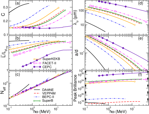
Figures 8 and 9 show the results of calculations performed for silicon(110)- and diamond(110)-based CU using and for the positron beams specified in Table 1. The dependences presented were obtained by maximizing the brilliance of CUR emitted in the fundamental harmonic. It is seen, that within the range of moderate values of the bending amplitude ( varies from several units up to several tens, graphs (e); and 1.92 Å for the diamond and silicon crystals, respectively) it is possible to construct a CU with sufficiently large number of effective periods, , graphs (c). These values correspond to the range of undulator periods m (graphs (d)) which is achievable by different methods of preparation of periodically-bent crystalline structures, see Section 3. It is seen from Figs. 8 and 9 that out of all calculated quantities the peak brilliance , graphs (f), is the most sensitive to the parameters of the positron beam. The variation in the magnitude of is over six orders of magnitude, from up to (compare the DANE and CEPC curves).
Appendix C Beam Demodulation in CU
In a CU, a channeling particle, while moving along the channel centerline, undergoes two other types of motion in the transverse directions with respect to the CU axis . First, there are channeling oscillations along the direction perpendicular to the crystallographic planes. Second, the particle moves along the planes (the direction). To be noted is that different particles have different (i) amplitudes of the channeling oscillations, and (ii) momenta in the plane due to the distribution in the transverse energy of the beam particles as well as the result of multiple scattering from crystal atoms. Therefore, even if the speed of all particles along their trajectories is the same, the difference in or/and in leads to different values of the velocities with which the particles move along the undulator axis. As a result, the beam loses its modulation while propagating through the crystal.
For an unmodulated beam, the CU length is limited mainly by the dechanneling process. A dechanneled particle does not follow the periodic shape of the channel, and, thus, does not contribute to the CUR spectrum. Hence, it is reasonable to estimate on the level of several dechanneling lengths (see panels (b) in Figs. 8 and 9). Longer crystals would attenuate rather then produce the radiation. Since the intensity of CUR is proportional to the undulator length squared, the dechanneling length and the attenuation length are the main restricting factors (see Section B) which must be accounted for.
For a modulated beam, the intensity is sensitive not only to the shape of the trajectory but also to the relative positions of the particles along the undulator axis. If these positions become random because of the beam demodulation, the coherence of CUR is lost even for the channeled particles. Hence, the demodulation becomes the phenomenon which imposes most restrictions on the parameters of a CU.
In Ref. [82] an important quantity, – the demodulation length, was introduced. It represents the characteristic scale of the penetration depth at which a modulated beam of channeling particles becomes demodulated. Within the framework of the approach developed in the cited papers the demodulation length is related to the dechanneling length in a bent channel:
| (11) |
Here is the first root of the Bessel function . The dimensionless parameter is expressed in terms of the emitted radiation frequency , the dechanneling length and Lindhard’s critical angle in the bent channel: (see [92] for the details). The function is related to the real and imaginary parts of the first root (with respect to ) of the equation [92]
| (12) |
where stands for Kummer’s confluent hypergeometric function (see, e.g., [98]).
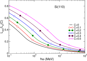
Eqs. (11) and (12) can be analyzed numerically to derive the dependence of the demodulation length on the radiation energy for a particular crystal channel. The result of such analysis is illustrated by Fig. 10 where the dependences of the ratio on the photon energy are presented for the (110) planar channels in diamond and silicon and for several values of the bending parameter as indicated. To be noted, is that for all values of the bending parameter and over broad energy range of the emitted radiation, the demodulation length is noticeably less than the dechanneling one.

To preserve the beam modulation during its channeling in a crystal and, as a result, to maintain the coherence of the radiation the crystal length must be less than the demodulation length:
| (13) |
It follows from (11) that in a periodically bent crystal depends on the crystal type, on the parameters of the channel (its width, strength of the interplanar field), on the bending amplitude and period, on the projectile energy and its type (these are ”hidden” in , , and ) as well as on the emitted photon energy (enters the parameter ). Therefore, Eq. (13) imposes addition restriction on the CU length as compared to the case of the CUR emission by the unmodulated beam.
In Ref. [92] it is also shown that the phase velocity of the modulated beam along the CU channel is modified as compared to the unmodulated one. The modification changes the resonance condition which links the parameters of the undulator and the radiated wavelength (energy). The expression for the fundamental harmonic frequency acquires the following form (compare with Eq. (3)):
| (14) |
where the additional term in the denominator is given by
| (15) |
with being another function related to the real and imaginary parts of the first root of Eq. (12) (details can be found in Refs. [92, 16]). The quantity depends on . Therefore, Eq. (14) represents a transcendent equation which relates to the projectile energy and to the bending amplitude and period.
Analysis of the formulae written above shows that for given values of and all other quantities which characterize the CU and the demodulation process can be expressed in terms of a single independent variable, for example, the bending amplitude . Then, scanning over the values it is possible to determine the whole set of the parameters (these include , , , ) which maximize the peak brilliance of the superradiant emission (see section D).
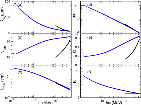
Figure 11 shows the results of calculations of the parameters of the diamond(110)-based CU which maximize the peak brilliance of the radiation of energy emitted by the FACET-II positron beam, see Table 1. The dependences presented correspond to the emission in the fundamental harmonic. The crystal thickness was set to the demodulation length , graph (e). The quantity stands for the number of undulator periods within the demodulation length, . Only the data corresponding to are shown in the panels. The dependences presented refer to the Large-Amplitude regime of the periodic bending, which implies that the amplitude exceeds the interplanar distance .
Noticing that the factor can be written in terms of the undulator parameter , one writes Eq. (14) as a quadratic equation with respect to . Resolving it one finds that is a two-valued function of , which is reflected in graph (f). As a result, all dependences presented contain two branches related to the smaller (black curves) and larger (blue curves) allowed values of .
Appendix D Brilliance of the Superradiant Emission in CU
Powerful superradiant emission by ultra-relativistic particles channeled can be achieved if the probability density of the particles in the beam is (uniformly) modulated in the longitudinal direction with the period equal to integer multiple to the wavelength of the emitted radiation [81].
To prevent the demodulation of the beam as it propagates through the crystal, the crystal length must satisfy condition (13). In a wide range of photon energies, starting with keV, the demodulation length is noticeably less than the dechanneling length . In addition to this, in this energy range the photon attenuation length in silicon and diamond greatly exceeds the dechanneling length of positrons with energies up to several tens of GeV [16]. Therefore, on the spatial scale of the dechanneling and the photon attenuation effects can be disregarded.
In what follows, we carry out quantitative estimates of the characteristics of the superradiant CU radiation (CUR) emitted by a fully modulated positron beam channeled in periodically bent diamond and silicon (110) oriented crystals in the absence of the dechanneling and the photon attenuation. The beam represents a train of bunches each of the length containing particles. The crystal length (along the beam direction) is set to the demodulation length, . The transverse sizes of a crystal are assumed to be larger than those of the beam, i.e. than .
For the sake of clarity, below we consider the emission in the first harmonics of CUR, see Eq. (14)
Final width of the CUR peak introduces a time interval within which two particles separated in space can emit coherent waves. Hence, one can introduce a coherence length [75]
| (16) |
where is the radiation wavelength, and the band-width (BW) with standing for the number of periods within the demodulation length.
The number of the particles from the bunch which emit coherently is calculated as
| (17) |
Their radiated energy is proportional to . The number of such sub-bunches is , therefore, the energy emitted by the whole bunch contains the factor .
Another important quantity to be estimated is the solid angle within which the waves emitted by the particles of the sub-bunch are coherent. This angle can be chosen as the minimum value from the natural emission cone of the first harmonics and the angle which ensures transverse coherence of the emission due to the finite sizes of the bunch. Assuming the elliptic form for the bunch cross section one derives . Therefore, the solid angle is found from
| (18) |
The number of photons emitted by the bunch particles one obtains multiplying the spectral-angular distribution of the energy emitted by a single particle by the factor . The result reads:
| (19) |
where with defined in (15).
The number of photons emitted by the particles of the unmodulated beam in a CU of the same length and number of periods one calculates from Eq. (2) written for by setting , substituting and multiplying the right-hand side by . Comparing the result with Eq. (19) one notices that the enhancement factor due to the coherence effect is .
Another quantity of interest is the flux of photons. Measured in the units of , it is related to as follows:
| (20) |
where is the time flight of the bunch and stands for the peak current.
The peak brilliance, , of the superradiant CUR one obtains substituting from (19) into Eq. (1) in the main text and using there peak current instead of .
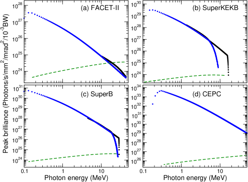
Figure 12 shows peak brilliance of radiation formed in the diamond(110)-based CU as functions of the first harmonic energy. Four graphs correspond to the positron beams (as indicated) the parameters of which are listed Table 1. In each graph, the dashed line refers to the the emission of the spontaneous CUR formed in the undulator with optimal parameters, see Fig. 9. The thick curves present the peak brilliance of the superradiant CUR maximized by the proper choice of the bending amplitude and period (as described in Section C). Two branches of this dependence, seen in graphs (a)-(c), are due to the two-valued character of the dependence of undulator parameter on the radiation frequency . For the CEPC beam, graph (d), this peculiarity manifests itself in the frequency domain beyond 40 MeV, therefore it is not seen in the graph.
References
References
- [1] E. A. Seddon, J. A. Clarke, D. J. Dunning, C. Masciovecchio, C. J. Milne, F. Parmigiani, D. Rugg, J. C. H. Spence, N. R. Thompson, K. Ueda, S. M. Vinko, J. S. Wark, E. Wurth. Short-wavelength free-electron laser sources and science: a review. Rep. Prog. Phys. 80, 115901 (2017).
- [2] A. Doerr. The new XFELs. Nature Meth. 13, 33 (2018).
- [3] Ch. J. Milne, Th. Schietinger, M. Aiba, A. Alarcon, J. Alex, et al. SwissFEL: The Swiss X-ray free electron laser. Appl. Scie. 7, 720 (2017).
- [4] P. Emma, R. Akre, J. Arthur, R. Bionta, C. Bostedt, et al. First lasing and operation of an Ångstrom-wavelength free-electron laser. Nat. Photonics 4, 641 (2010).
- [5] B. W. J. McNeil and N. R. Thompson. X-ray free-electron lasers. Nat. Photonics 4, 814 (2010).
- [6] Ch. Bostedt, S. Boutet, D. M. Fritz, Z. Huang, H. J. Lee, H. T. Lemke, A. Robert, W. F. Schlotter, J. J. Turner, G. J. Williams. Linac coherent light source: The first five years. Rev. Mod. Phys. 88, 015007 (2016).
- [7] M. Yabashi and H. Tanaka. The next ten years of X-ray science. Nat. Photonics 11, 12 (2017).
- [8] V. Ayvazyan, N. Baboi, I. Bohnet, R. Brinkmann, M. Castellano, et al. A new powerful source for coherent VUV radiation: Demonstration of exponential growth and saturation at the TTF free-electron laser. Europ. Phys. J. D 20, 149 (2002).
- [9] M. Krasny. The Gamma Factory proposal for CERN. CERN Proc. 1, 249 (2018). (doi:10.23727/CERN-Proceedings-2018-001.249)
- [10] Xenon beams light path to gamma factory. CERN Courier (13 October 2017). https://cerncourier.com/xenon-beams-light-path-to-gamma-factory/
- [11] K. A. Olive et al. (Particle Data Group). Review of Particle Physics. Chin. Phys. C 38, 090001 (2014).
- [12] A. V. A. V. Korol, Solov’yov and W. Greiner. Coherent radiation of an ultrarelativistic charged particle channeled in a periodically bent crystal. J. Phys. G: Nucl. Part. Phys. 24, L45 (1998).
- [13] A. V. A. V. Korol, Solov’yov and W. Greiner. Photon emission by an ultra-relativistic particle channeling in a periodically bent crystal. Int. J. Mod. Phys. E 8, 49 (1999).
- [14] A. V. A. V. Korol, Solov’yov and W. Greiner. Channeling of positrons through periodically bent crystals: On the feasibility of crystalline undulator and gamma-laser. Int. J. Mod. Phys. E 13, 897 (2004).
- [15] W. Greiner, A. V. Korol, A. Kostyuk and A. V. Solov’yov. Vorrichtung und Verfahren zur Erzeugung electromagnetischer Strahlung, Application for German patent, June 14, Ref.: 10 2010 023 632.2 (2010).
- [16] A. V. A. V. Korol, Solov’yov and W. Greiner. Channeling and Radiation in Periodically Bent Crystals, Second ed., Springer-Verlag, Berlin, Heidelberg, 2014.
- [17] G. B. Sushko, A. V. Korol and A. V. Solov’yov. A small-amplitude crystalline undulator based on 20 GeV electrons and positrons: Simulations. St. Petersburg Polytechnical Uni. J.: Phys. Math. 1, 341 (2015).
- [18] J. Lindhard. Influence of crystal lattice on motion of energetic charged particles. K. Dan. Vidensk. Selsk. Mat. Fys. Medd. 34, 1 (1965).
- [19] L. Bandiera, E. Bagli, G. Germogli, V. Guidi, A. Mazzolari, H. Backe, W. Lauth, A. Berra, D. Lietti, M. Prest, D. De Salvador, E. Vallazza and V. Tikhomirov. Investigation of the electromagnetic radiation emitted by sub-GeV electrons in a bent crystal. Phys. Rev. Lett. 115, 025504 (2015).
- [20] I. A. Solov’yov, A. V. Korol and A. V. Solov’yov. Multiscale Modeling of Complex Molecular Structure and Dynamics with MBN Explorer. Springer International Publishing, Cham, Switzerland (2017).
- [21] U. Uggerhøj. The interaction of relativistic particles with strong crystalline fields. Rev. Mod. Phys. 77, 1131 (2005).
- [22] M. A. Kumakhov. On the theory of electromagnetic radiation of charged particles in a crystal. Phys. Lett. 57A, 17 (1976).
- [23] R. W. Terhune and R. H. Pantell. X-ray and -ray emission from channeled relativistic electrons and positrons. Appl. Phys. Lett. 30, 265 (1977).
- [24] C. A. Brau, B.-K. Choi, J. D. Jarvis, J. W. Lewellen and P. Piot. Channeling Radiation as a Source of Hard X-rays with High Spectral Brilliance. Synchrotron Radiat. News 25, 20 (2012).
- [25] W. Wagner, B. Azadegan, M. Sobiella, J. Steiner, K. Zeil and J. Pawelke. An intense channeling radiation source. Nucl. Instrum. Meth. B 266, 327 (2008).
- [26] M. Tanabashi et al. (Particle Data Group): Review of Particle Physics, Phys. Rev. D 98, 030001 (2018).
- [27] K. Akai, K. Furukawa and H. Koiso. SuperKEKB Collider. Preprint at https://arXiv:1809.01958 (2018).
- [28] The CEPC Study Group. CEPC Conceptual Design Report. Preprint at https://arXiv:1809.00285 (2018).
- [29] E. N. Tsyganov. Fermilab Preprints TM-682: Some aspects of the mechanism of a charged particle penetration through a monocrystal. & TM-684: Estimates of Cooling and bending processes for charged particle penetration through a monocrystal. (Fermilab, Batavia, 1976).
- [30] A. F. Elishev, N. A. Filatova, V. M. Golovatyuk, I. M. Ivanchenko, R. B. Kadyrov et al. Steering of charged particle trajectories by a bent crystal. Phys. Lett. B88, 387 (1979).
- [31] V. M. Biryukov, Yu. A., Chesnokov and V. I. Kotov. Crystal Channeling and its Application at High-Energy Accelerators. (Springer Science & Business Media, 2013).
- [32] W. Scandale, M. Fiorini, V. Guidi, A. Mazzolari, D. Vincenzi, et al. Measurement of the dechanneling length for high-energy negative pions. Phys. Lett. B719, 70 (2013).
- [33] W. Scandale, A. Carnera, G. D. Mea, D. De Salvador, R. Milan et al. Deflection of 400 GeV/c proton beam with bent silicon crystals at the CERN Super Proton Synchrotron. Phys. Rev. ST AB 11, 063501 (2008).
- [34] W. Scandale, A. Vomiero, S. Baricordi, P. Dalpiaz, M. Fiorini et al. Experimental study of the radiation emitted by 180 GeV/c electrons and positrons volume-reflected in a bent crystal. Phys. Rev. A 79, 012903 (2009).
- [35] R. P. Fliller III, A. Drees, D. Gassner, L. Hammons, G. McIntyre, S. Peggs, D. Trbojevic, V. Biryukov, Yu. Chesnokov and V. Terekhov. Results of bent crystal channeling and collimation at the Relativistic Heavy Ion Collider. Phys. Rev. ST AB 9, 013501 (2006).
- [36] A. Mazzolari, E. Bagli, L. Bandiera, V. Guidi, H. Backe, W. Lauth, V. Tikhomirov, A. Berra, D. Lietti, M. Prest, E. Vallazza and D. De Salvador. Steering of a sub-GeV electron beam through planar channeling enhanced by rechanneling. Phys. Rev. Lett. 112, 135503 (2014).
- [37] H. Shen, Q. Zha, F. S. Zhang, G. B., G. B. Sushko, A. V. Korol, and A. V. Solov’yov, Channeling and radiation of 855 MeV electrons and positrons in straight and bent tungsten (1 1 0) crystals. Nucl. Instrum. Meth. B 424, 26 (2018).
- [38] A. Kostyuk. Crystalline undulator with a small amplitude and a short period. Phys. Rev. Lett. 110, 115503 (2013).
- [39] T. N. Wistisen, K. K. Andersen, S. Yilmaz, R. Mikkelsen, J. L. Hansen, U. I. Uggerhøj, W. Lauth and H. Backe Experimental realization of a new type of crystalline undulator. Phys. Rev. Lett. 112, 254801 (2014).
- [40] U. I. Uggerhoj, T. N. Wistisen, J. L. Hansen, W. Lauth and P. Klag. Radiation collimation in a thick crystalline undulator. Eur. J. Phys. D 71, 124 (2017).
- [41] A. V. Korol, V. G. Bezchastnov, G. B. Sushko and A. V. Solov’yov. Simulation of channeling and radiation of 855 MeV electrons and positrons in a small-amplitude short-period bent crystal. Nucl. Instrum. Meth. B 387, 41 (2016).
- [42] U. I. Uggerhøj and T. N. Wistisen. Intense and energetic radiation from crystalline undulators. Nucl. Instrum Meth. B 355, 35 (2015).
- [43] V. G. Bezchastnov, A. V. Korol, and Solov’yov, A. V. Radiation from multi-GeV electrons and positrons in periodically bent silicon crystal. J. Phys. B 47, 195401 (2014).
- [44] H. Backe, D. Krambrich, W. Lauth, B. Buonomo, S. B., Dabagov, G. Mazzitelli, L. Quintieri, J. L. Hansen, U. K. I. Uggerhøj, B. Azadegan, A. Dizdar and W. Wagner. Future aspects of X-ray emission from crystal undulators at channeling of positrons. Nuovo Cimento C 34, 175 (2011).
- [45] V. T. Baranov, S. Bellucci, V. M. Biryukov, G. I. Britvich, V. N. Chepegin et al. Preliminary results on the study of radiation from positrons in a periodically deformed crystal. Nucl. Instrum. Meth. B 252, 32 (2006).
- [46] M. Tabrizi, M., A. V. Korol, A. V. Solov’yov and W. Greiner. Feasibility of an electron-based crystalline undulator. Phys. Rev. Lett. 98, 164801 (2007).
- [47] H. Backe, D. Krambrich, W. Lauth, J. L. Hansen and U. K. I. Uggerhøj. X-ray emission from a crystal undulator: experimental results at channeling of electrons. Nuovo Cimento C 34, 157 (2011).
- [48] H. Backe, D. Krambrich, W. Lauth, K. K. Andersen, J. L. Hansen and U. K. Uggerhøj. Radiation emission at channeling of electrons in a strained layer Si1-xGex undulator crystal. Nucl. Instum. Meth. B 309, 44 (2013).
- [49] A. V. Korol, A. V. Solov’yov and W. Greiner. Total energy losses due to the radiation in an acoustically based undulator: the undulator and the channeling radiation. Int. J. Mod. Phys. E 9, 77 (2000).
- [50] S. Bellucci, S. Bini, V. M. Biryukov, Yu. A. Chesnokov et al. Experimental study for the feasibility of a crystalline undulator. Phys. Rev. Lett. 90, 034801 (2003).
- [51] P. Balling, J. Esberg, K. Kirsebom, D. Q. S. Le, U. I. Uggerhøj, S. H. Connell, J. Härtwig, F. Masiello and A. Rommeveaux. Bending diamonds by femto-second laser ablation. Nucl. Instrum Meth. B 267, 2952 (2009).
- [52] V. Guidi, A. Antonioni, S. Baricordi, F. Logallo, C. Malagù, E. Milan, A. Ronzoni, M. Stefancich, G. Martinelli and A. Vomiero. Tailoring of silicon crystals for relativistic-particle channeling. Nucl. Instrum. Meth. B 234, 40 (2005).
- [53] E. Bagli, L. Bandiera, V. Bellucci, A. Berra, R. Camattari, D. De Salvador, G. Germogli, V. Guidi, L. Lanzoni, D. Lietti, A. Mazzolari, M. Prest, V. V. Tikhomirov and E. Valla. Experimental evidence of planar channeling in a periodically bent crystal. Eur. Phys. J. C 74, 3114 (2014).
- [54] V. Guidi, A. Mazzolari, G. Martinelli, and A. Tralli. Design of a crystalline undulator based on patterning by tensile Si3N4 strips on a Si crystal. Appl. Phys. Lett. 90, 114107 (2007).
- [55] V. Guidi, L. Lanzoni, and A. Mazzolari. Patterning and modeling of mechanically bent silicon plates deformed through coactive stresses. Thin Solid Films 520, 1074 (2011).
- [56] V. Bellucci, R. Camattari, V. Guidi, A. Mazzolari, G. Paterno, G. Mattei, C., Scian and L. Lanzoni. Ion implantation for manufacturing bent and periodically bent crystals. Appl. Phys. Lett. 107, 064102 (2015).
- [57] R. Camattari, G. Paternò, M. Romagnoni, V. Bellucci, A. Mazzolari and V. Guidi. Homogeneous self-standing curved monocrystals, obtained using sandblasting, to be used as manipulators of hard X-rays and charged particle beams. J. Appl. Cryst. 50 (2017) 145-151.
- [58] F. Cristiano, M. Shayesteh, R. Duffy, K. Huet, F. Mazzamuto, Y. Qiu, M. Quillec, H. H. Henrichsen, P. F. Nielsen, D. H. Petersen, A. La Magna, G. Caruso and S. Boninelli. Defect evolution and dopant activation in laser annealed Si and Ge. Mat. Scie. in Semicond. Process. 42 (2016) 188-195
- [59] S. A. Bogacz and J. B. Ketterson. Possibility of obtaining coherent radiation from a solid state undulator. J. Appl. Phys. 60, 177 (1986).
- [60] U. Mikkelsen and E. Uggerhøj. A crystalline undulator based on graded composition strained layers in a superlattice. Nucl. Instum. Meth. B 160, 435 (2000).
- [61] H. Backe, D. Krambrich, W. Lauth, K. K. Andersen, J. L. Hansen and U. I. Uggerhøj. Radiation emission at channeling of electrons in a strained layer Si1-xGex undulator crystal. Nucl. Instum. Meth. B 309, 37 (2013).
- [62] T. N. Tran Thi, J. Morse, D. Caliste, B. Fernandez, D. Eon, J. Härtwig, C. Barbay, C. Mer-Calfati, N. Tranchant, J. C. Arnault, T. A. Lafford and J. Baruchel. Synchrotron Bragg diffraction imaging characterization of synthetic diamond crystals for optical and electronic power device applications. J. Appl. Cryst. 50, 561 (2017).
- [63] B. G. de la Mata, A. Sanz-Hervás, M. G. Dowsett, M. Schwitters and D. Twitchen. Calibration of boron concentration in CVD single crystal diamond combining ultralow energy secondary ions mass spectrometry and high resolution X-ray diffraction. Diamond and Rel. Mat. 16, 809 (2007).
- [64] V. G. Baryshevsky, I. Ya. Dubovskaya and A. O. Grubich. Generation of -quanta by channeled particles in the presence of a variable external field. Phys. Lett. 77A, 61 (1980).
- [65] V. V. Kaplin, S. V. Plotnikov and S. A. Vorobev. Radiation by charged particles in deformed crystals. Sov. Phys. – Tech. Phys. 25, 650 (1980).
- [66] H. Ikezi, Y. R. Lin-Liu and T. Ohkawa. Channeling radiation in periodically distorted crystal. Phys. Rev. B 30, 1567 (1984).
- [67] A. R. Mkrtchyan, R. H. Gasparyan, R. G. Gabrielyan and A. G. Mkrtchyan. Channeled positron radiation in the longitudinal and transverse hypersonic wave field. Phys. Lett. 126A, 528 (1988).
- [68] G. V. Dedkov. Channeling radiation in a crystal undergoing an action of ultrasonic or electromagnetic waves. Phys. Stat. Sol. (b) 184, 535 (1994).
- [69] W. Wagner, B. Azadegan, H. Büttig, L. Sh. Grigoryan, A. R. Mkrtchyan and J. Pawelke. Channeling radiation on quartz stimulated by acoustic waves. Nuovo Cimento C 34, 134 (2011).
- [70] E. Tzianaki, M. Bakarezos, G. B. Tsibidis, Y. Orphanos, P. A. Loukakos, C. Kosmidis, P. Patsalas, M. Tatarakis and N. A. Papadogiannis. High acoustic strains in Si through ultrafast laser excitation of Ti thin-film transducers. Opt. Express 23 (2015) 17191-17204.
- [71] M. Bakarezos, E. Tzianaki, S. Petrakis, G. Tsibidis, P. A. Loukakos, V. Dimitriou, C. Kosmidis, M. Tatarakis and N. A. Papadogiannis. Ultrafast laser pulse chirp effects on laser‐generated nanoacoustic strains in Silicon. Ultrasonics 86 (2018) 14-19.
- [72] L. Federici, G. Giordano, G. Matone, G. Pasquariello, P. Picozza. et al. The LADON photon beam with the ESRF 5 GeV machine. Lett. Nuovo Cimento 27, 339 (1980).
- [73] Haseeb ur Rehman, Jiyoung Lee, and Yonghee Kim. Optimization of the laser-Compton scattering spectrum for the transmutation of high-toxicity and long-living nuclear waste. Ann. Nucl. Energy 105, 150 (2017).
- [74] J. M. Krämer, A. Jochmann, M. Budde, M. Bussmann, J. P. Couperus et al. Making spectral shape measurements in inverse Compton scattering a tool for advanced diagnostic applications. Scie. Reports 8, 139 (2018).
- [75] P. Schmüser, M. Dohlus and J. Rossbach. Ultraviolet and Soft X-Ray Free-Electron Lasers. Springer, Berlin/Heidelberg (2008).
- [76] M. Altarelli and A. Salam. The quest for brilliance: light sources from the third to the fourth generation. Europhysicsnews 35, 47 (2004).
- [77] P. Rullhusen, X. Artru and P. Dhez. Novel Radiation Sources Using Relativistic Electrons. World Scientific, Singapore (1998).
- [78] K.-J. Kim. Characteristics of synchrotron radiation. In: X-ray Data Booklet, pp. 2.1–2.16. Lawrence Berkeley Laboratory, Berkley (2009). (http://xdb.lbl.gov/xdb-new.pdf)
- [79] K.-J. Kim. Brightness, coherence and propagation characteristics of synchrotron radiation. Nucl. Instrum. Meth. A 246, 71 (1986).
- [80] E. G. Bessonov. Theory of parametric free-electron lasers. Sov. J. Quantum Electron. 16, 1056 (1986).
- [81] A. Gover, A. Friedman, C. Emma, N. Sudar, P. Musumeci and C. Pellegrini. Superradiant and stimulated-superradiant emission of bunched electorn beams. Rev. Mod. Phys. 91, 035003 (2019).
- [82] A. Kostyuk, A. V. Korol, A. V. Solov’yov and W. Greiner. Stable propagation of a modulated particle beam in a bent crystal channel. J. Phys. B: At. Mol. Opt. Phys. 43, 151001 (2010).
- [83] I. A. Solov’yov, A. V. Yakubovich, P. V. Nikolaev, I. Volkovets and A. V. Solov’yov. MesoBioNano Explorer - a universal program for multiscale computer simulations of complex molecular structure and dynamics. J. Comp. Chem. 33, 2412 (2012).
- [84] K. W. D. Ledingham, P. McKenna and R. P. Singhal. Applications for nuclear phenomena generated by ultra-intense lasers. Science 300, 1107 (2003).
- [85] K. W. D. Ledingham, R. P. Singhal, P. McKenna and I. Spencer. Laser-induced nuclear physics and applications. Europhys. News 33, 120 (2002).
- [86] B. M. Weon, J. H. Je, Y. Hwu and G. Margaritondo. Decreased surface tension of water by hard-X-ray irradiation. Phys. Rev. Lett. 100, 217403 (2008).
- [87] SLAC Site Office: Preliminary Conceptual Design Report for the FACET-II Project at SLAC National Accelerator Laboratory. Report SLAC-R-1067, SLAC (2015).
- [88] K. Nakamura et al. (Particle Data Group): Review of Particle Physics, J. Phys. G: Nucl. Part. Phys. 37, 075021 (2010).
- [89] M. Banks. Italy cancels €1bn SuperB collider. Physics World (2012) https://physicsworld.com/a/italy-cancels-1bn-superb-collider/
- [90] A. V. Korol, A. V. Solov’yov and W. Greiner. Number of photons and brilliance of the radiation from a crystalline undulator. Proc. of SPIE 5974, 45 (2005).
- [91] T. N. Wistisen, U. I. Uggerhøj, U. Wienands, T. W. Markiewicz, R. J. Noble, B. C. Benson, T. Smith, E. Bagli, L. Bandiera, G. Germogli, V. Guidi, A. Mazzolari, R. Holtzapple and S. Tucker. Channeling, volume reflection, and volume capture study of electrons in a bent silicon crystal. Phys. Rev. Acc. Beams 19, 071001 (2016).
- [92] A. Kostyuk, A. V. Korol, A. V. Solov’yov and W. Greiner. Demodulation of a positron beam in a bent crystal channel. Nucl. Instrum. Meth. B 269, 1482 (2011).
- [93] A. I. Sytov, L. Bandiera, D. De Salvador, A. Mazzolari, E. Bagli, A. Berra, S. Carturan, C. Durighello, G. Germogli, V. Guidi, P. Klag, W. Lauth, G. Maggioni, M. Prest, M. Romagnoni, V. V. Tikhomirov and E. Vallazza. Steering of Sub-GeV electrons by ultrashort Si and Ge bent crystals. Eur. Phys. J. C 77, 901 (2017).
- [94] J. H. Hubbel and S. M. Seltzer. Tables of X-ray mass attenuation coefficients and mass energy-absorption coefficients from 1 keV to 20 MeV for elements Z 1 to 92 and 48 additional substances of dosimetric interest. NISTIR 5632. Web version http://www.nist.gov/pml/data/xraycoef/index.cfm
- [95] H. Backe, W. Lauth and T. N. Tran Thi. Channeling experiments at planar diamond and silicon single crystals with electrons from the Mainz Microtron MAMI, J. Instrum. (JINST) 13, C04022 (2018).
- [96] U. Wienands, T. W. Markiewicz, J. Nelson, R. J. Noble, J. L. Turner, U. I. Uggerhøj, T. N. Wistisen, E. Bagli, L. Bandiera, G. Germogli, V. Guidi, A. Mazzolari, R. Holtzapple, and M. Miller. Observation of deflection of a beam of multi-GeV electrons by a thin crystal. Phys. Rev. Let. 114, 074801 (2015).
- [97] G. B. Sushko, V. G. Bezchastnov, I. A. Solov’yov, A. V. Korol, W. Greiner and A. V. Solov’yov. Simulation of ultra-relativistic electrons and positrons channeling in crystals with MBN Explorer. J. Comp. Phys. 252, 404 (2013).
- [98] M. Abramowitz and I. E. Stegun. Handbook of mathematical functions. Dover, New York (1964)