Innovative Telecommunications Training through Flexible Radio Platforms
Abstract
The ever-changing telecommunication industry is in severe need of a highly-skilled workforce to shape and deploy future generation communication systems. This article presents an innovative telecommunication training that is designed to satisfy this need. The training focuses on hardware layers of the open systems interconnection model. It integrates theory, numerical modeling, and hardware implementation to ensure a complete and long-lasting understanding. The key telecommunication concepts that are covered in the fundamental training phase are detailed along with best teaching practices. In addition, the methods that enrich the learning experience, such as gamified micro-tasks and interactive use of daily telecommunication devices, are featured. The project development case studies that cultivate creative thinking and scientific interest are highlighted. Also, a well-established guideline to compose the teaching environment that emphasizes hands-on experience is provided. Therefore, the presented training can be exemplary to other institutions that share the same mission to educate the distinguished engineers of the future.
Index Terms:
Engineering education, hands-on experience, interactive learning, teaching environment.I Introduction
Telecommunication technologies have been evolving from smoke signals to deep space high-definition video conferences at an accelerating pace [1, 2]. Such a thriving technology requires a vast number of highly skilled engineers. Therefore, a well-designed training is needed to satisfy the ever-changing telecommunication industry’s thirst for resilient professionals. Distinguished telecommunication engineers must have a solid understanding of the fundamental theory, an ability to translate this theoretical knowledge to the numerical implementation, and capability of implementing them in hardware. Also, they must be equipped with independent thinking and creative problem-solving skills to pioneer future telecommunication systems. Furthermore, these prodigious engineers have to express their ideas clearly and function effectively on a team.
This article presents an innovative telecommunications training that is designed to cultivate equipped telecommunication engineers by instilling the following abilities:
-
•
To identify, formulate, and solve telecommunication systems’ problems by applying principles of mathematics, digital signal processing (DSP), electromagnetic (EM) wave propagation, and communication theory.
-
•
To apply these fundamental concepts to design and test spectral/energy-efficient advanced telecommunication systems considering a wide variety of system scenarios, channel conditions, and hardware limitations.
-
•
To present designs and document outcomes taking a diverse audience into account.
The training emphasizes hands-on experience and focuses on hardware layers of the open systems interconnection (OSI) model [3]. At least a senior-level standing in electrical engineering is required for the proposed training. Not only students but also industry professionals who are looking to expand their understanding of telecommunications are targeted. Although there exist several courses considering either a particular technology [4, 5, 6] or a teaching method [7, 8], the proposed training covers various telecommunication technologies and integrates many modern teaching methods such as gamified micro-tasks and novel doubly dispersive channel emulators. The foundations of the suggested training were laid in [9], and the training is rebuilt by including emerging concepts, contemporary teaching methods, and futuristic projects over the last decade.
II Modern Teaching Methodologies
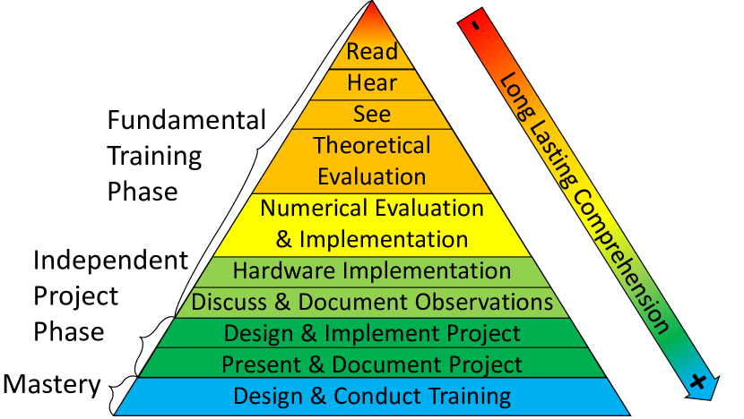
Comprehending certain subjects such as telecommunications is very challenging due to their highly abstract nature. The classical theoretical training prevents observing the immediate relationship between cause and effect. Also, theoretical knowledge without practice is destined to perish. A complete understanding can be achieved by an interactive learning experience [10, 11] as shown in Fig. 1. The proposed telecommunication engineering training is structured to modernize such a well-proven methodology.
A solid design builds on a good understanding of theoretical concepts. However, telecommunication systems exhibit numerous non-linear behaviors that make them difficult to model with closed-form expressions. Therefore, numerical models are widely used to assist in the evaluation and visualization of such complex systems. Trainees can manipulate the system and sub-system parameters independently and grasp their individual effects using various numerical tools. These skills are especially critical in their professional career since troubleshooting problems with such tools are easier than fixing them in the hardware prototyping stage. Nonetheless, the validity of the aforementioned models is limited by the assumptions. Therefore, theoretically and numerically verified designs must also be implemented in hardware and tested under various channel conditions and realistic scenarios. The hardware implementation can be achieved practically using flexible radio platforms. Also, it should be pointed out that the numerical and hardware implementations provide a convenient way for trainees to design telecommunication systems by themselves and assist reinforced learning.
The fundamental concepts of hardware layers are modularized and taught separately to examine each sub-system rigorously. In light of the discussions above, an ideal training should integrate theory, numerical modeling, and hardware implementation to train future telecommunication engineers well. Therefore, each training module starts with a theoretical discussion, followed by numerical analysis, and is completed with hardware implementation in the laboratory. The laboratory experiments feature telecommunication devices that are used daily such as smartphones and FM radio receivers to interest trainees. Furthermore, gamified micro-tasks motivates them and establishes confidence in this challenging field. The details of each module are given in the following section. At the end of each module, trainees are expected to deliver a technical report summarizing their key observations. These reports allow receiving immediate feedback regarding trainees’ progress and help them keep on track throughout the fundamental training phase. Upon successful completion of this phase, trainees are examined, and they proceed to the independent project development phase to demonstrate their vast proficiency on the topic.
III Design of a Telecommunication Engineering Training
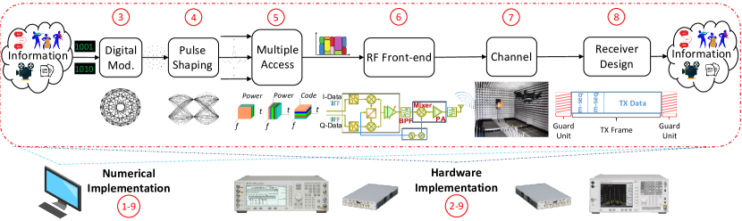
The proposed training teaches telecommunications with an emphasis on physical, data link, and network layers. The training content presents the journey of bits through telecommunication systems as depicted in Fig. 2. An instructor must compose the teaching environment carefully to deliver this content effectively. Once the teaching environment is established, the fundamental training and independent project development phases can be conducted. The total training duration depends on the audience. For example, the training is offered to students in 15 weeks, whereas the training is delivered to industry professionals on various extents. A good rule of thumb would be to allocate of the fundamental training period for the independent project development phase.
III-A The composition of a Telecommunication Teaching Environment
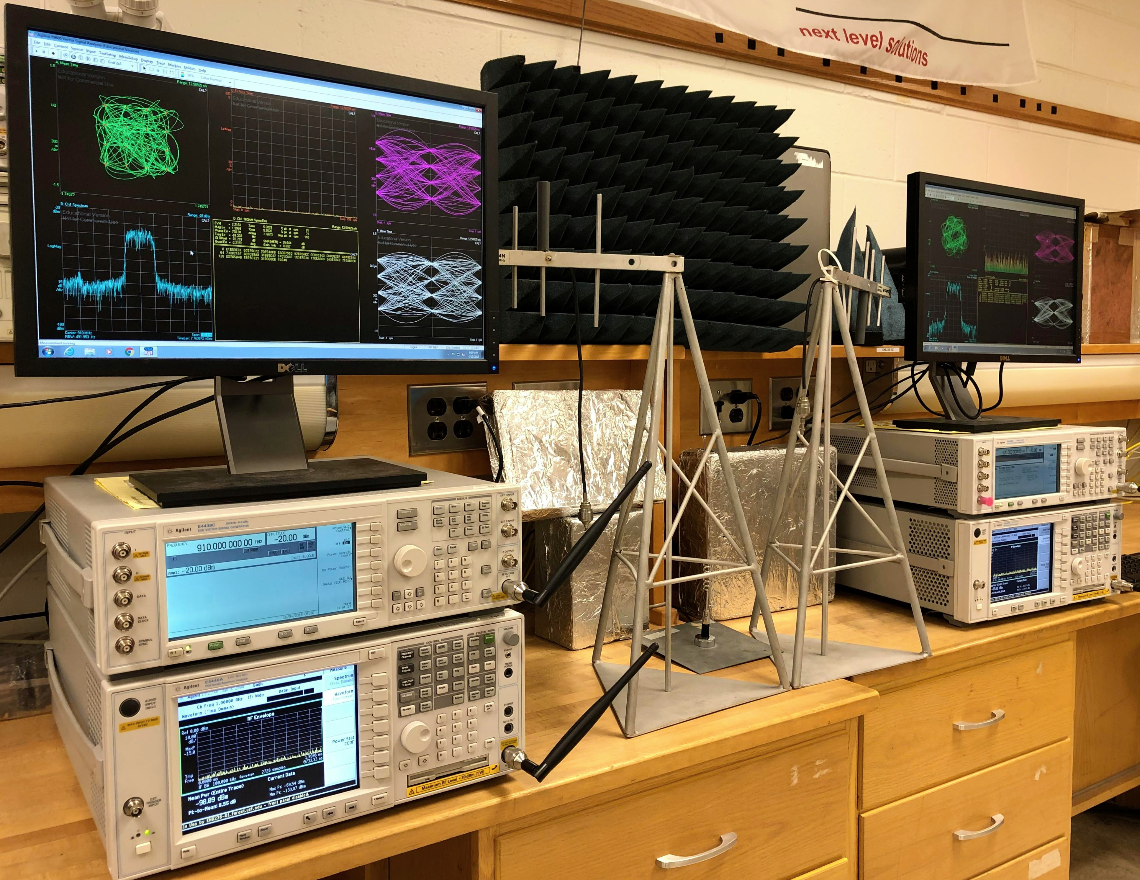
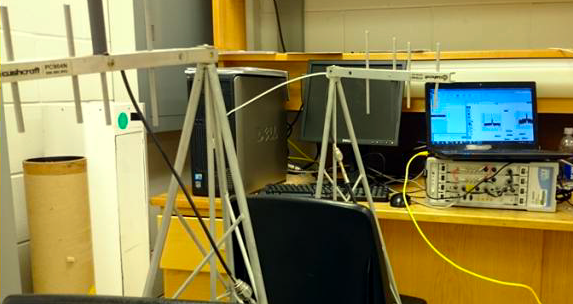
The theoretical content and numerical modeling can be taught either in a conventional computer laboratory or remotely. On the other hand, the hardware implementation requires a flexible radio platform that consists of software-defined radio (SDR) capable transmitter and receivers along with the modular RF front-end and configurable channel emulators. A basic SDR test-bed includes a vector signal generator (VSG), a vector signal analyzer (VSA), and a computer that runs telecommunication system design and analysis tools as well as cables/antennas as shown in Fig. 3. A VSG can generate signals using various digital modulation techniques and baseband pulse shapes. Also, it can multiplex them in various domains such as time, frequency, and code to obtain standard and custom waveforms. These waveforms can either be generated internally using the VSG in standalone operation or externally using the computer, and are conveyed to VSAs. A VSA has the ability to demodulate the standard and custom signals in a standalone mode similar to a VSG. Also, it can convey the in-phase and quadrature (IQ) samples of the received signal to a computer for processing. The interaction between a computer and VSGs/VSAs is an excellent mechanism for teaching, studying, and analyzing the current and upcoming telecommunication systems.
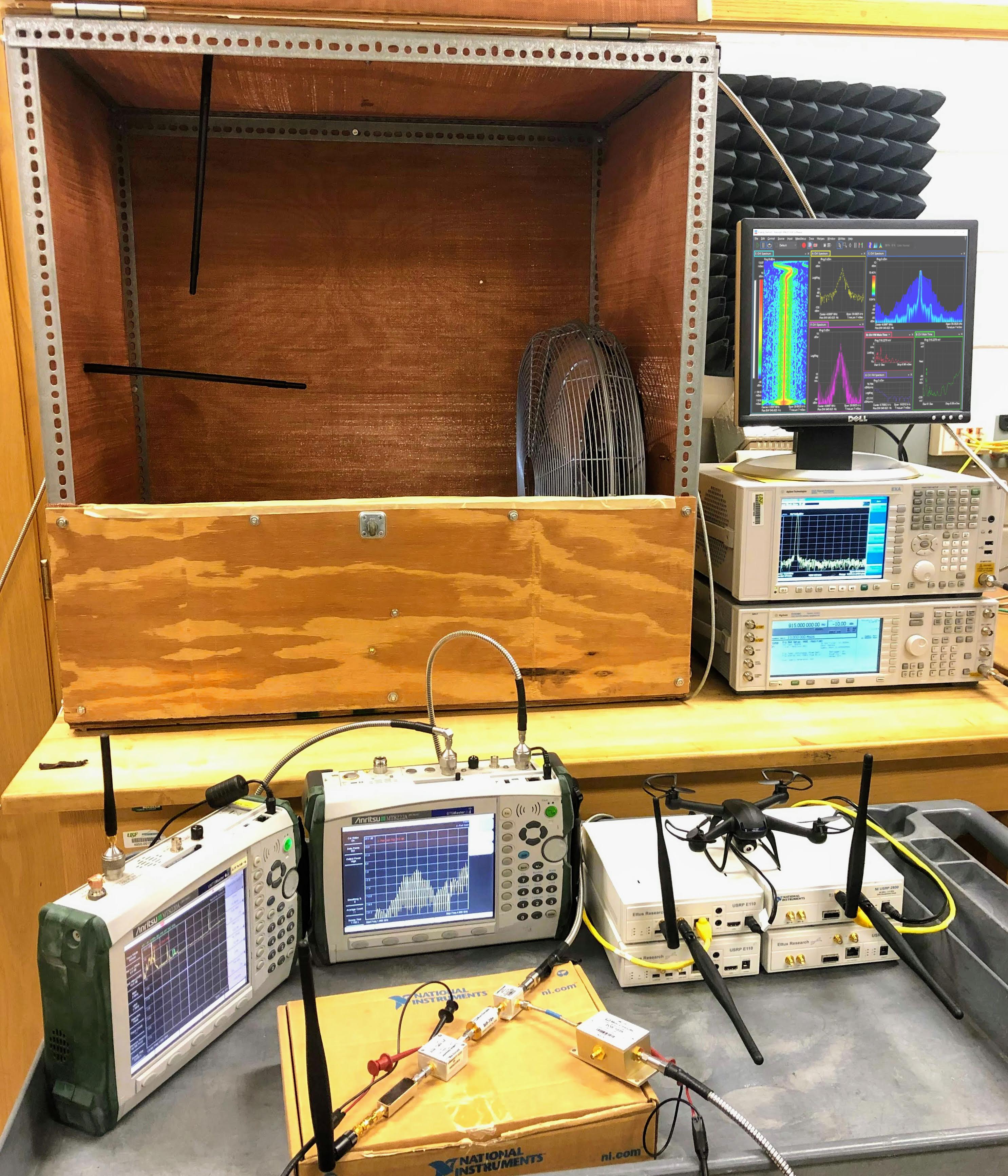
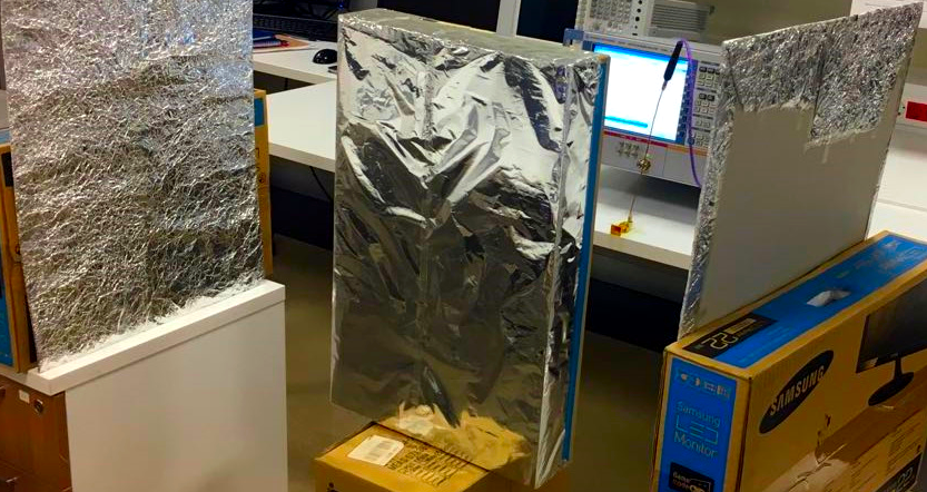
The system design, scenarios, and channel conditions can be enriched further by extending the test-bed with mobile transceivers, modular RF front-end, and channel emulation tools as presented in Fig. 4. IQ modems, digital to analog converters (DACs), analog to digital converters (ADCs), mixers, voltage-controlled oscillators (VCOs), power amplifiers (PAs), band-pass filters (BPFs), cables, and antennas are some of the critical RF front-end components of telecommunication systems. Testing and measuring a telecommunication system using a modular RF front-end provides the ability to analyze the function and effect of each component separately. In addition, mobile transceivers allow emulating various scenarios such as cellular hand-off and positioning. For high accuracy requirements, handheld VSGs and VSAs are preferable, whereas an abundance of low-cost SDR hardware is more convenient for experienced trainees to emulate applications involving networking and interference management. Furthermore, diverse channel conditions can be mimicked via reverberation and anechoic chambers, unmanned aerial vehicles (UAVs), and metal fans [12]. The frequency selectivity of the channel is controlled through the use of chambers, whereas time selectivity is managed using multi-speed fans.
III-B Fundamental Training Phase
Basic telecommunication concepts can be taught in eight modules as numbered in Fig. 2. Also, the final module adapts trainees to contemporary telecommunication systems. A detailed description is provided in the training website111http://wcsp.eng.usf.edu/courses/wcsl.html, and the key components of these modules are summarized as follows:
III-B1 Introduction to the Basic Telecommunication Concepts
In this module, the theoretical aspects of the concepts that will be covered throughout the training are introduced. Also, a transceiver is modeled numerically to present the complete picture of a telecommunication system. First, text messages for each test-bed are encoded to bits, modulated, pulse-shaped, and multiplexed into different bands in the presence of additive white Gaussian noise by the instructor. The waveforms are supplied to trainees with combinations of various RF impairment (i.e., frequency offset, phase noise, and PA nonlinearities) levels and signal to noise ratios (SNRs). Trainees are required to down-convert the signals and develop baseband receiver algorithms to complete the gamified microtask of this module, which is detecting individualized transmitted messages. Also, trainees assess the performance through the observation of bit error rate (BER) and several diagrams such as constellation, IQ polar, and eye. The benefit of this module is twofold. First, trainees get familiar with the identification of telecommunication systems’ problems. Second, trainees become acquainted with utilizing numerical tools to design and analyze telecommunication systems.
III-B2 Introduction to the Basic SDR Test-bed
The primary objective of this module is to familiarize trainees with a basic SDR test-bed. Trainees generate standard single-carrier and multi-carrier waveforms at the VSGs and assess their performances using the built-in functions of the VSAs along with the corresponding computer software. The concepts that are theoretically and numerically covered in the first module are implemented in the hardware. The instructor allocates a different portion of the ISM band to each test-bed, and trainees practice transceiving custom telecommunication signals. Not only the signals that are generated by VSGs but also over the air signals such as FM, Wi-Fi, and PCS are analyzed in this module. Observing the FM radio spectrum interests trainees and relates the taught concepts to daily life. Also, the burst transmission structure in ISM and PCS bands upon Wi-Fi and cellular calls is demonstrated. In the last part of the module, the received signal at VSA is downloaded to a computer, and spectro-temporal characteristics are analyzed using numerical tools. This part is especially important to illustrate the interconnection between the components of a basic SDR test-bed.
III-B3 Digital Modulation
Trainees commence the telecommunication system design by mapping bits to symbols after the overview in the first two modules. The theory part of the module teaches the purpose of digital modulation and its limiting factors such as SNR and peak-to-average power ratio (PAPR). In the numerical and hardware implementation parts, various modulation schemes are demonstrated using built-in functions and characterized in terms of power efficiency, spectral efficiency, and ease of implementation. The analyses start with the throughput comparison of BPSK and higher-order QAM and PSK modulation schemes as a function of SNR to demonstrate the trade-off between spectral and energy efficiency. This trade-off is made clear through the observation of error vector magnitude (EVM), IQ polar diagram, eye diagram, and power CCDF curve. After initial characterization, alternative modulation schemes such as /2-BPSK, /4-DQPSK, OQPSK, and MSK that enhance PAPR to overcome hardware limitations at the expense of implementation complexity are demonstrated and examined. After trainees comprehend the distinguishing characteristics of various digital modulation schemes, the instructor transmits a signal, and trainees attempt to figure out the digital modulation scheme blindly. Trainees understand the motivation behind the existence of various digital modulation schemes and link adaptation to channel conditions in this module.
III-B4 Baseband Pulse Shaping
The objective of this module is to study the impact of baseband pulse shaping filters, which map digitally modulated symbols into waveforms, on telecommunication system performance. The discussions take off with orthogonal raised-cosine (RC) filters. Trainees alter the roll-off parameter that controls the spectro-temporal characteristics, and they observe changes in the spectrum, time envelope, power CCDF curve, IQ polar diagram, and eye diagram. Furthermore, the performance of the RC pulse shaping filter at the transmitter side is compared with using root-raised-cosine (RRC) pulse shaping filter at both transmitter and receiver, and superiority of matched filtering is demonstrated. Also, an RRC pulse-shaped signal is transmitted without matched filtering at the receiver, and the presence of inter-symbol interference is pointed out. Once trainees are accustomed to the non-orthogonality in the filter design, the discussion continues with Gaussian pulse shaping filters that are preferred due to their spectral confinement. The similarity between the bandwidth-time (BT) product of Gaussian pulse shaping filters and the roll-off factor of RC pulse shaping filters are pointed out. GSM signals with different BT products are generated, and their performances are evaluated as similar to RC pulse-shaped signals. After understanding the spectro-temporal characteristics of baseband pulse shaping filters, the instructor transmits signals, and trainees predict the filter parameters. The fundamentals for spectral- and energy-efficient design are taught in this module, and robust filter design against RF front-end impairments and multiple access wireless channel are further elaborated in the following modules.
III-B5 Multiple Accessing
The purpose of this module is to acquaint trainees with resource allocation among multiple users and to manage resulting interference. Previously, the test-beds share the channel in an FDMA manner. In this module, they get familiarized with other multiple accessing schemes such as TDMA and CDMA. Initially, GSM signals with varying relative burst powers for each slot are broadcasted by the instructor. Each slot is assigned to a certain test-bed along with associated relative burst power. Trainees observe the TDMA frame structure and locate their slot. In the following stage, the instructor transmits various DSSS-CDMA signals by assigning different codes to each test-bed. As the number of active codes increases, trainees observe the power CCDF curve and conclude that an increased number of random variables degrades PAPR characteristics. Also, a joint time-frequency analysis is performed on Bluetooth signals from two smartphones using the spectrogram. The smartphones’ distances to a VSA are utilized to identify the hopping structure of each frequency hopping spread spectrum code.
Upon introducing conventional resource allocation techniques, multiple access interference is explained. Adjacent channel interference (ACI) is demonstrated by transmitting equipower RRC pulse-shaped signals in adjacent bands simultaneously without a guard band in between. Although the test-beds can demodulate their signals with slight performance degradation, they cannot demodulate each others’ signals properly due to the near/far effect. In this step, trainees utilize their knowledge from the previous module and adjust the RRC roll-off factor to mitigate ACI. In the next stage, test-beds generate single-carrier signals at the same frequency and emulate a co-channel interference scenario. They observed that their communication performance significantly degrades since there is an insufficient spatial separation between the test-beds. Afterward, one of the test-beds switches to the DSSS scheme, and it is demonstrated that spread spectrum systems are more robust against narrowband interference. This module integrates previously learned concepts and improves multi-dimensional signal analysis skills.
III-B6 RF Front-end
Teaching the functionalities and characteristics of critical RF front-end components is the core objective of this experiment. In the first stage of this module, the instructor informs trainees on IQ modems and familiarize them with various impairments using the internal IQ modulator on VSGs. IQ gain imbalance, quadrature offset, and DC offset are intentionally introduced, and their effect on IQ polar diagram, eye diagram, and EVM are exhibited. Following this stage, quantization effects are demonstrated by connecting an external DAC with various resolutions to VSGs and altering the dynamic range of VSAs. Trainees observe the results of quantization errors such as spectral regrowth, increase in EVM, interpolation issues in eye and IQ polar diagrams. Afterward, the analog signal is conveyed to an upconverter unit that consists of a mixer and a VCO to shift the baseband signal to IF or RF. Trainees compare the stability of low-end standalone VCOs’ output with that of VSGs. The reference signals generated by both VCOs are passed through mixers for upconversion. It is demonstrated that low-end standalone VCOs cannot output stable tones and produce phase noise.
Trainees analyze the effect of nonlinear behavior of mixers and PAs. First, they observe the spectrum while operating the PA in the linear region. Hence, the harmonics generated only by the mixer are presented. Afterward, the transmitted power is gradually increased, and power CCDF curve, EVM, IQ polar diagram, and spectrum are observed. It is demonstrated that increasing the transmit power beyond the hardware limitations does not increase SNR. BPFs are provided to suppress harmonics caused by both components. Furthermore, PAPR is reduced by using digital modulation techniques that omit zero-crossings and utilizing RRC pulse shapes with a higher roll-off factor. Thus, trainees understand both the inconveniences of these devices and techniques to cope with their disadvantages. Also, this module provides them an opportunity for building a complete RF front-end by connecting all the aforementioned components.
III-B7 Propagation Channel
The purpose of this module is to present fundamental EM wave propagation concepts. The channel imposes various effects on EM waves such as distance and frequency-dependent path loss, large scale fading (i.e., shadowing), and small scale fading (i.e., delay spread and Doppler spread). In the first stage, the distance- and frequency-dependent characteristics of the path loss are depicted by measuring the signal with different antenna separations at different frequencies. Trainees sweep the FM band and record the received power levels of various stations. They obtain the transmit power, antenna height, and distance information online. Afterward, a simple statistical path loss model is derived considering the measurements from the stations with the same parameters. Also, shadowing is demonstrated by pointing out the variation around the path loss.
Small scale fading can originate from two phenomena; namely, delay spread and Doppler spread. In the second stage, a reverberation chamber is used to control the delay spread amount in an indoor environment. Trainees alter the transmission bandwidth, and they observe a frequency selective channel when the signal bandwidth exceeds the coherence bandwidth of the channel. It is challenging to demonstrate mobility in an indoor environment. Either the transceiver or the environment must be mobilized. A multi-speed metal fan is utilized to create the variation in time. Trainees place a metal fan in between two antennas and operate it at different speeds while monitoring the spectrogram. Furthermore, a doubly-dispersive channel is emulated by moving the fan inside the reverberation chamber [12, 13]. Finally, trainees apply the concepts that are discussed in the previous modules to design telecommunication systems robust against channel effects. For example, the symbol rate is decreased to elevate immunity to delay spread, whereas it is increased to boost resistance to Doppler spread. Furthermore, the RRC roll-off factor is raised to improve the performance in both spreads with a penalty of degraded spectral localization.
III-B8 Receiver Design
The objective of this module is designing a complete digital baseband receiver. The instructor transmits a BPSK modulated TDMA frame. The frame consists of individualized messages following different repeated m-sequences for each test-bed. Trainees capture the signal and record it for offline processing. They start with the coarse time synchronization step to pinpoint the position of their desired message. Since two m-sequences are appended back to back, their autocorrelation gives a rough estimate of the allocated slot beginning. Upon the coarse time synchronization step, the frequency offset amount is estimated using the constant delay between the consecutive m-sequences. The estimated frequency offset is compensated for the frequency synchronization. Then, fine time synchronization is performed by cross-correlating the local m-sequence copy with the frequency offset compensated signal. Trainees downsample the signal at the best sampling locations using the fine time synchronization information. Afterward, channel estimation must be carried out to compensate for the channel effect. The m-sequence of the received signal is compared with the local m-sequence copy in order to estimate the wireless channel. The phase and amplitude of the received signal are corrected upon estimation. In the final stage, digital demodulation is performed, and estimated bits are mapped to characters to reveal the transmitted information. Trainees are thrilled to be able to demodulate a physical signal similar to their daily devices. This module finalizes the modules that are pointed out in the functional diagram on Fig. 2 and demonstrates a complete picture of a basic single-carrier communication system.
III-B9 OFDM
The main features of OFDM modulation are studied in the last training module. The instructor supplies trainees with a cyclic prefix (CP)-OFDM transmission script along with the VSG and VSA connection libraries. In the first stage, trainees are expected to develop their OFDM baseband receiver algorithms similar to the previous module. Since there is no m-sequence in the frame, CP is used for time and frequency synchronization. Trainees repeat the hardware implementation steps of RF front-end and propagation channel modules for multi-carrier communication after the receiver design. FFT size, number of active subcarriers, CP length, and modulation order are altered in each step, and their effect on the telecommunication system performance is analyzed through power CCDF curve, constellation, and spectrum. Also, they compare the impairments for single-carrier and multi-carrier communication schemes and point out the main differences. This module combines all the concepts that are covered in this training within the perspective of an advanced modulation scheme that is used in current cellular and Wi-Fi systems.
III-C Independent Project Development Phase
Trainees become ready to pursue independent projects upon the completion of the fundamental training phase. Although novelty is not enforced, it is highly encouraged. Considering the last 50+ projects that are completed under the authors’ supervision, the feasible and educational projects are categorically summarized to inspire prospective trainees as follows:
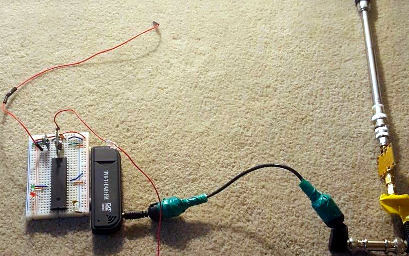
III-C1 Software-defined radio (SDR)
The expertise acquired with the higher-end SDR platforms in the fundamental training phase equips trainees with the ability to build their low-cost SDRs. These projects are especially suitable for embedded system developers seeking to implement the Internet of Things transceivers. Fig. 5a depicts an exemplary PIC driven FSK transmitter with its RF front-end. The budget-limited SDR hardware comes with the price of excessive RF front-end impairments. Trainees must also develop advanced baseband algorithms to mitigate IQ impairments, PA nonlinearities, and low-resolution DAC/ADC quantization issues.
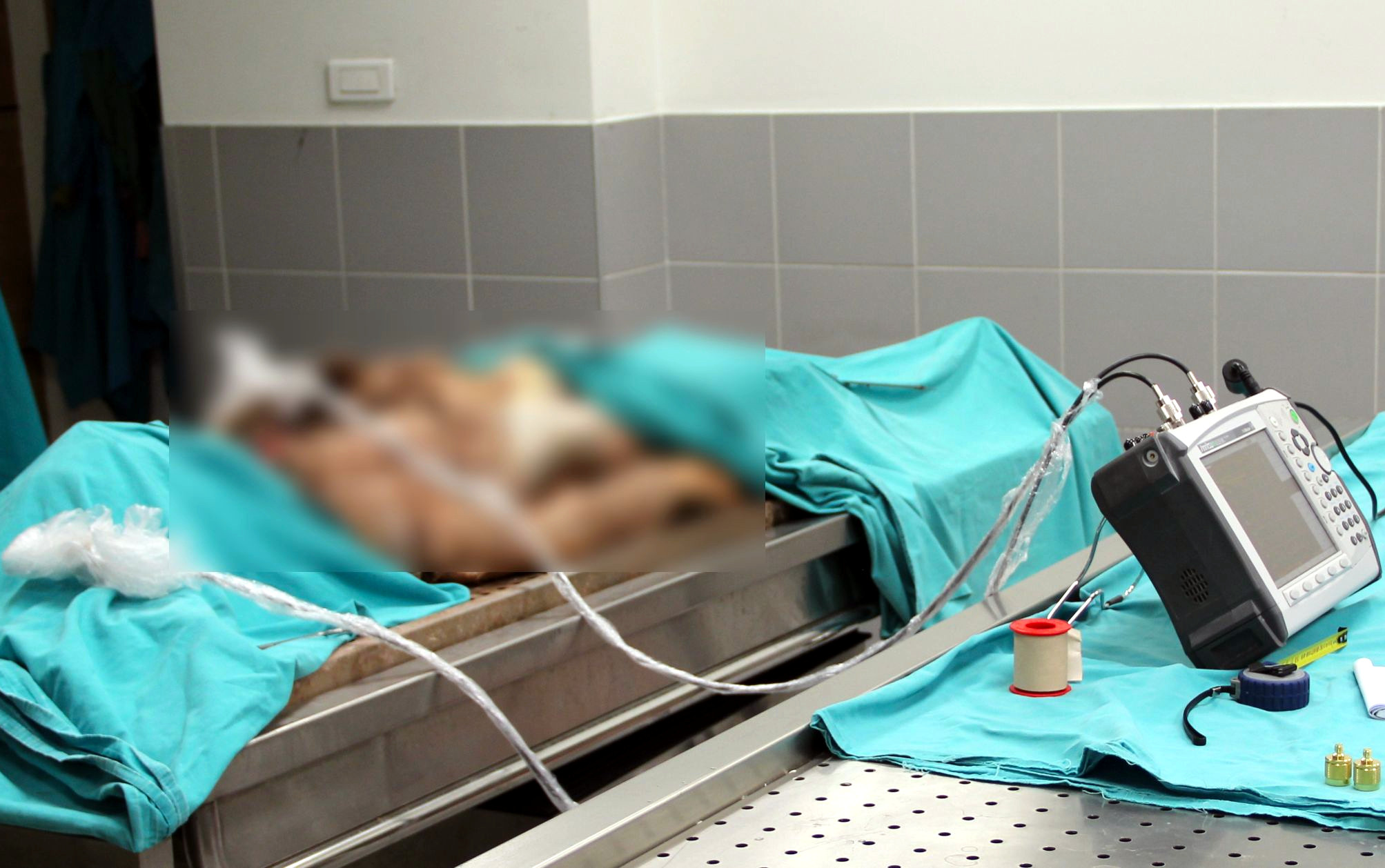
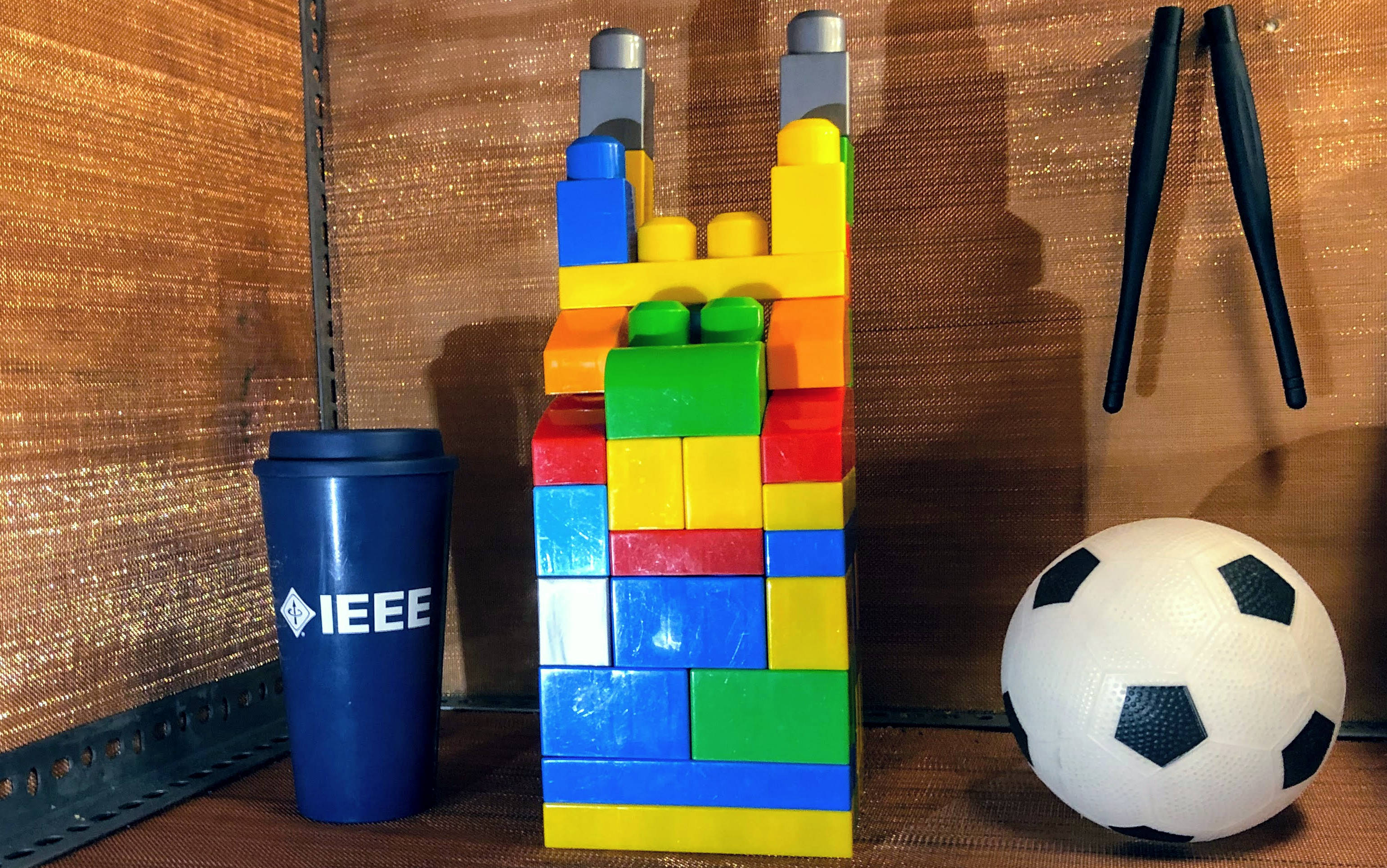
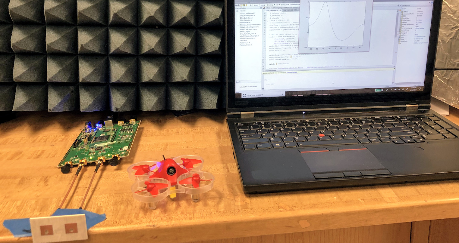
III-C2 Wireless channel
The fundamental training phase provides the ability to comprehend basic features of conventional cellular and WiFi channels. Trainees with strong propagation engineering backgrounds may characterize and model different environments such as the promising in body channel (Fig. 5b [14]). Furthermore, advanced channel features can be extracted to determine line-of-sight/non-line-of-sight conditions or to design an object identifier via machine learning (Fig. 5c). Location services driven by channel properties are also compelling projects. Triangular positioning, channel-based authentication, distance and angle-of-arrival estimation (Fig. 5d) techniques are exemplary candidates. Moreover, the novel doubly-dispersive channel emulators [12, 13] used in the fundamental training phase were originally designed and implemented as trainee projects.
III-C3 Wireless channel counteractions
After obtaining a well-understanding in channel characteristics, trainees can exploit them to improve telecommunication systems further. For example, MIMO systems are designed to take advantage of spatial diversity. Trainees with antenna and RF circuit design experience prefer MIMO front-end design and manufacturing (Fig. 5e), whereas trainees with solid communication theory background favor MIMO power allocation, channel estimation, and compensation projects. Furthermore, the mmW channel, which will be deployed in 5G, can be studied as well. For instance, the mmW blockage issue is dealt with an adaptive antenna beamwidth implementation as shown in Fig. 5f [15].
III-C4 Signal intelligence
Trainees with DSP and communication theory backgrounds may utilize their extensive knowledge on multi-dimensional signal analysis, and communication channel to pursue signal intelligence applications. These applications include non-data aided blind receivers which estimate various parameters such as symbol rate, modulation type, and pulse shaping filter parameters in the presence of RF front-end and channel impairments. Furthermore, trainees can conceal the transmitted signal to prevent eavesdropping using various single- and multi-antenna physical layer security techniques such as artificial noise transmission. Also, trainees may utilize channel-based authentication methods to identify the legitimate transmitter as well.
III-C5 Multiple access and interference management
The fundamental training phase mostly covers the centralized and orthogonal multiple accessing schemes. Alternative schemes such as cognitive radio (CR) and non-orthogonal multiple access (NOMA) attract trainees with data link layer interest and cultivate numerous projects. For example, the spectrum is utilized opportunistically in CR, and trainees avoid interfering the primary user. Furthermore, non-contiguous frequency resources can be aggregated in these projects. NOMA is another spectral-efficient resource utilization scheme and can be realized with multi-user detection, blind source separation, and interference cancellation algorithms. Moreover, trainees may manage self-interference and develop full-duplex communication schemes to improve the capacity of telecommunication systems.
III-C6 Standards
Trainees can improve their expertise in telecommunication systems by partially implementing hardware layers of various standards such as 3G/4G/5G cellular, IEEE 802.11, Bluetooth, and stereo FM. In addition, those interested in network layer may realize vertical handoff mechanisms to switch between different standards in a heterogeneous network scenario. Mobile SDR equipment is essential in these projects. Moreover, trainees can asses new technologies for future standards. For example, various waveforms might be implemented to evaluate their performances in realistic scenarios considering diverse channel conditions, multiple access interference, and RF front-end impairments.
IV Trainee Improvement
The fundamental training phase, which integrates theory, numerical modeling, and hardware implementation, leads to competent telecommunication engineers with a solid education. Trainees who completed the training are distinguished in their further telecommunication education and career. Their academic success was tracked, and their superiority to those who had not completed this training is revealed in both [9, Table V] and Table I. Student final scores in telecommunications-related courses from 2016 to 2019 are analyzed. Seventy students who have taken this training succeed better in the listed courses than 330 students who have not as presented in Table I. Also, [9, Table IV] points out that they feel more confident with telecommunication system design and analysis after the training.
The independent project development phase requires trainees to acquire and apply new knowledge as needed without well-defined instructions and sharpens their analysis and synthesis skills. Also, it promotes teamwork and generates synergistic engineers. Trainees improve their presentation skills by demonstrating their projects effectively to a wide range of audience that includes undergraduate students, graduate students, faculty, and industry professionals. Discussions that take place during presentations and feedback received afterward are reportedly beneficial for professional interviews. The documentation of projects benefits technical writing skills. Furthermore, notable projects are encouraged for publication, and scientific interest among trainees is cultivated.
Finally, the instructors who are assisting trainees throughout their telecommunication education journey also benefit from tutoring, which completes their mastery as pointed out in Fig. 1.
![[Uncaptioned image]](/html/1910.11825/assets/x3.png)
V Conclusions
The industry and academia require well-trained telecommunication engineers. The proposed training is a well-established guideline to educate outstanding engineers and to build a bridge between these two institutions by integrating theoretical proficiency, numerical modeling skills, and hands-on experience. The provided array of skills as well as professional qualities help trainees to succeed in their professional journeys and to design future generation telecommunication systems. Other institutions that are willing to set up a similar training can profit from the experiences shared in this article. Especially, the improvement of trainees confirm the effectiveness and make the proposed training a candidate for the flagship training of telecommunication education.
Acknowledgment
The authors would like to thank former trainees: J. Olivo, A. Menon, M. F. Kucuk, N. Soulandros, and G. Gillespie for their outstanding projects that are presented in Fig. 5. Also, we would like to thank USF professors: R. D. Gitlin, N. Ghani, S. Morgera, and Z. Lu for their courteously supplied academic success statistics that are demonstrated in Table I.
References
- [1] S. Parkvall, E. Dahlman, A. Furuskar, and M. Frenne, “NR: The new 5G radio access technology,” IEEE Communications Standards Magazine, vol. 1, no. 4, pp. 24–30, Dec 2017.
- [2] D. Consonni and M. T. M. Silva, “Signals in communication engineering history,” IEEE Trans. Educ., vol. 53, no. 4, pp. 621–630, Nov 2010.
- [3] Information technology – Open Systems Interconnection – Network service definition, International Organization for Standardization Standard ISO/IEC 8348:2002, Rev. 3, Nov. 2002.
- [4] W. T. Padgett, B. A. Black, and B. A. Ferguson, “Low-frequency wireless communications system-infrared laboratory experiments,” IEEE Trans. Educ., vol. 49, no. 1, pp. 49–57, Feb 2006.
- [5] F. A. Cassara, “Wireless communications laboratory,” IEEE Trans. Educ., vol. 49, no. 1, pp. 132–140, Feb 2006.
- [6] Y. Linn, “An ultra low cost wireless communications laboratory for education and research,” IEEE Trans. Educ., vol. 55, no. 2, pp. 169–179, May 2012.
- [7] H. Aliakbarian, P. J. Soh, S. Farsi, H. Xu, E. H. E. M. J. C. V. Lil, B. K. J. C. Nauwelaers, G. A. E. Vandenbosch, and D. M. M.-P. Schreurs, “Implementation of a project-based telecommunications engineering design course,” IEEE Trans. Educ., vol. 57, no. 1, pp. 25–33, Feb 2014.
- [8] S. M. Berber and K. W. Sowerby, “Visual presentation of abstract theoretical concepts using animations in communication systems courses,” Computer Applications in Engineering Education, vol. 26, no. 1, pp. 49–61, 2018.
- [9] S. Güzelgöz and H. Arslan, “A wireless communications systems laboratory course,” IEEE Trans. Educ., vol. 53, no. 4, pp. 532–541, Nov 2010.
- [10] E. Dale, Audio-visual methods in teaching, 3rd ed. New York: Holt, Rinehart & Winston, 1969.
- [11] N. Hoic-Bozic, V. Mornar, and I. Boticki, “A blended learning approach to course design and implementation,” IEEE Trans. Educ., vol. 52, no. 1, pp. 19–30, Feb 2009.
- [12] S. Güzelgöz, S. Yarkan, and H. Arslan, “Investigation of time selectivity of wireless channels through the use of RVC,” Measurement, vol. 43, no. 10, pp. 1532–1541, 2010.
- [13] A. B. Kihero, M. Karabacak, and H. Arslan, “Emulation techniques for small scale fading aspects by using reverberation chamber,” IEEE Trans. Antennas Propag., vol. 67, no. 2, pp. 1246–1258, Feb 2019.
- [14] A. F. Demir, Q. H. Abbasi, Z. E. Ankarali, A. Alomainy, K. Qaraqe, E. Serpedin, and H. Arslan, “Anatomical region-specific in vivo wireless communication channel characterization,” IEEE J. Biomed. Health Inform., vol. 21, no. 5, pp. 1254–1262, Sept 2017.
- [15] S. Dogan, M. Karabacak, and H. Arslan, “Optimization of antenna beamwidth under blockage impact in millimeter-wave bands,” in Proc. 2018 IEEE 29th Annu. Int. Symp. Personal, Indoor and Mobile Radio Commun., Bologna, IT, Sep. 2018, pp. 1–5.
![[Uncaptioned image]](/html/1910.11825/assets/Bio01_AFD.png) |
Ali Fatih Demir (S’08) received the B.S. degree in electrical engineering from Yıldız Technical University, Istanbul, Turkey, in 2011 and the M.S. degrees in electrical engineering and applied statistics from Syracuse University, Syracuse, NY, USA in 2013. He is currently pursuing the Ph.D. degree as a member of the Wireless Communication and Signal Processing (WCSP) Group in the Department of Electrical Engineering, University of South Florida, Tampa, FL, USA. His current research interests include PHY and MAC aspects of wireless communication systems, in vivo wireless communication systems, and signal processing/machine learning algorithms for brain-computer interfaces. |
![[Uncaptioned image]](/html/1910.11825/assets/Bio02_BP.jpg) |
Berker Peköz (GS’15) received the B.S. degree in electrical and electronics engineering from Middle East Technical University, Ankara, Turkey in 2015, and the M.S.E.E. from University of South Florida, Tampa, FL, USA in 2017. He was a Co-op Intern at the Space Division of Turkish Aerospace Industries, Inc., Ankara, Turkey in 2013, and a Summer Intern at the Laboratory for High Performance DSP & Network Computing Research, New Jersey Institute of Technology, Newark, NJ, USA in 2014. He is currently pursuing the Ph.D. at University of South Florida, Tampa, FL, USA. His research is concerned with standard compliant waveform design and optimization. Mr. Peköz is a member of Tau Beta Pi. |
![[Uncaptioned image]](/html/1910.11825/assets/Bio03_SK.png) |
Selçuk Köse (S’10–M’12) received the B.S. degree in electrical and electronics engineering from Bilkent University, Ankara, Turkey, in 2006, and the M.S. and Ph.D. degrees in electrical engineering from the University of Rochester, Rochester, NY, USA, in 2008 and 2012, respectively. He was an Assistant Professor of Electrical Engineering at the University of South Florida, Tampa, FL, USA. He is currently an Associate Professor of Electrical and Computer Engineering at University of Rochester, Rochester, NY, USA. His current research interests include integrated voltage regulation, 3-D integration, hardware security, and green computing. Dr. Köse was a recipient of the NSF CAREER Award, the Cisco Research Award, the USF College of Engineering Outstanding Junior Researcher Award, and the USF Outstanding Faculty Award. He has served on the Technical Program and Organization Committees of various conferences. He is currently an Associate Editor of the World Scientific Journal of Circuits, Systems, and Computers and the Elsevier Microelectronics Journal. |
![[Uncaptioned image]](/html/1910.11825/assets/Bio04_HA.png) |
Hüseyin Arslan (S’95–M’98–SM’04–F’15) received the B.S. degree in electrical and electronics engineering from Middle East Technical University, Ankara, Turkey in 1992, and the M.S. and Ph.D. degrees in electrical engineering from Southern Methodist University, Dallas, TX, USA in 1994 and 1998, respectively. From January 1998 to August 2002, he was with the research group of Ericsson Inc., Charlotte, NC, USA, where he was involved with several projects related to 2G and 3G wireless communication systems. He is currently a Professor of Electrical Engineering at the University of South Florida, Tampa, FL, USA, and the Dean of the College of Engineering and Natural Sciences at the İstanbul Medipol University, İstanbul, Turkey. His current research interests are on 5G and beyond, waveform design, advanced multiple accessing techniques, physical layer security, beamforming and massive MIMO, cognitive radio, dynamic spectrum access, interference management (avoidance, awareness, and cancellation), co-existence issues on heterogeneous networks, aeronautical (high altitude platform) communications, millimeter-wave communications and in vivo communications. He has served as technical program committee chair, technical program committee member, session and symposium organizer, and workshop chair in several IEEE conferences. He is currently a member of the editorial board for the IEEE Communications Surveys and Tutorials and the Sensors Journal. |