Molecular platform for frequency upconversion at the single-photon level
Abstract
Direct detection of single photons at wavelengths beyond 2 microns under ambient conditions remains an outstanding technological challenge. One promising approach is frequency upconversion into the visible (VIS) or near-infrared (NIR) domain, where single photon detectors are readily available. Here, we propose a nanoscale solution based on a molecular optomechanical platform to up-convert photons from the far and mid-infrared (covering part of the THz gap) into the VIS-NIR domain. We perform a detailed analysis of its outgoing noise spectral density and conversion efficiency with a full quantum model. Our platform consists in doubly resonant nanoantennas focusing both the incoming long-wavelength radiation and the short-wavelength pump laser field into the same active region. There, infrared active vibrational modes are resonantly excited and couple through their Raman polarizability to the pump field. This optomechanical interaction is enhanced by the antenna and leads to the coherent transfer of the incoming low-frequency signal onto the anti-Stokes sideband of the pump laser. Our calculations demonstrate that our scheme is realizable with current technology and that optimized platforms can reach single photon sensitivity in a spectral region where this capability remains unavailable to date.
I Introduction
Many applications in security, material science and healthcare would benefit from the development of new technologies for far and mid-infrared (FIR and MIR, respectively) detection and thermal imaging tonouchi_cutting-edge_2007. Driven by applications in astronomy, novel cryogenic detectors in the FIR range appeared in the past few years ariyoshi_terahertz_2016; bueno_full_2017. However the ability to efficiently manipulate such electromagnetic signals at room temperature is still lacking sizov_terahertz_2018; rogalski_two-dimensional_2019. In particular, single photon detection, which is now routine in the VIS-NIR region (wavelength in vacuum from 400 to 2000 nm), remains impossible or unpractical at longer wavelengths. The development of new detection devices operating without complex cryogenic apparatus, and featuring improved sensitivity, lower noise and reduced footprint, would significantly impact sensing, imaging, spectroscopy and communication technologies.
In this work we propose a new route to achieve low-noise detection of non-coherent radiation between 5-50 THz by leveraging optomechanical transduction with molecules roelli_molecular_2016, whose natural oscillation frequencies are resonant with the incoming field. Our strategy consists in converting the incoming low-frequency signal onto the anti-Stokes sideband of a pump laser in the VIS-NIR domain, where detectors with single photon sensitivity are readily available goltsman_picosecond_2001; hadfield_single-photon_2009. This approach is inspired by the recent realization of coherent frequency conversion using different types of optomechanical cavities tian_optical_2010; dong_optomechanical_2012; hill_coherent_2012; palomaki_coherent_2013; bochmann_nanomechanical_2013; andrews_bidirectional_2014; forsch_microwave--optics_2020 and is conceptually distinct from a recently demonstrated detection scheme assisted by a microfabricated resonator belacel_optomechanical_2017. As an outlook, we propose to leverage constructive interference between signals coming from an array of coherently pumped up-converters in order to increase further the strength of the converted signal over the incoherent thermal noise.
While coherent conversion from the MIR to the VIS-NIR domain has so far been achieved by sum-frequency generation in bulk nonlinear crystals boyd2008nonlinear; karstad_detection_2005; tidemand-lichtenberg_mid-infrared_2016; tseng_upconversion_2018, these schemes operate under several watts of pump power and require phase-matching between the different fields propagating in the crystal. Our scheme, on the contrary, relies solely on the spatial overlap of the two incoming fields. Indeed, we use a nanometer-scale dual antenna that confines both electromagnetic fields into similar sub-wavelength mode volumes. The optomechanical interaction with the vibrational system takes place in the near field, without need to fulfill a phase matching condition. Moreover, thanks to the giant field enhancement provided by plasmonic nanogaps, the required pump power to achieve efficient conversion is dramatically reduced.
The protocol that we introduce leverages the intrinsic ability of specific molecular vibrations to interact both resonantly with MIR-FIR fields and parametrically with VIS-NIR fields, as routinely observed in infrared absorption and Raman spectroscopy, respectively. The wealth of accessible vibrational modes and frequencies herzberg_molecular_1960; colthup_introduction_1990 offers a convenient toolbox to realize efficient frequency upconversion in the technologically appealing region of thermal imaging.
We first introduce the framework describing the interaction between a molecular vibration and two electromagnetic fields, one that is resonant with the vibrational frequency, the other one that is parametrically coupled to it through the molecular polarization. We compute the conversion efficiency and the noise figures of merit of our novel device as a function of the optical pump detuning and power. We illustrate the achievable performance with a device operating at 30 THz (10 m) and find internal conversion efficiencies on the order of a few percent and noise-equivalent power below W/. Finally, we demonstrate how our approach may be used to reach single-photon detection at frequencies down to THz.
II Optical conversion scheme
We start with the description of the two types of interactions leveraged in the conversion process and describe the relevant parameters. For simplicity, we now use the abbreviation IR to denote MIR or FIR fields, depending on the vibrational frequency considered. First we model the resonant absorption process. We assume that the vibrational system is weakly driven, meaning that the average number of excited collective vibrational quanta is much smaller that the total number of molecular oscillators coupled to the incoming field, . At the single-molecule level, this easily satisfied condition corresponds to neglecting transitions beyond the ground and first excited vibrational states. The collective excitation of an ensemble of vibrational modes can thus be treated as an ensemble of two-level systems shalabney_coherent_2015.
The interaction part of the Hamiltonian is correspondingly approximated by :
| (1) |
with the IR field bosonic ladder operators and the raising and lowering operators of the collective two level system described by a transition frequency . is the collective resonant vacuum coupling rate of the vibrational mode for identical molecules, and the mean occupation of the IR antenna mode.
The incoming IR field at frequency is enhanced by a frequency-matched antenna and performs work on the collective transition dipole of the molecular vibration cohen-tannoudji_atom-photon_1992. On resonance the average number of created phonons is (see Appendix C for a detailed derivation)
| (2) |
with the incoming IR photon flux. In this expression is the loss rate of the antenna at the incoming frequency, which is the sum of the external decay rate (by radiative coupling to the far-field modes) and the internal decay rate (by absorption in the metal). is the coupling ratio of the antenna and the total vibrational decay rate, where the intrinsic vibrational linewidth is modified by its coupling to the IR antenna metzger_purcell-enhanced_2019 and the optomechanical interaction with the pump laser, as explained below.

(a)\SetVerticalPole\imagecoffinleft3pt+\CoffinWidth\labelcoffin/2\SetVerticalPole\imagecoffinright\Width-3pt-\CoffinWidth\labelcoffin/2\SetHorizontalPole\imagecoffinup\Height-4pt-\CoffinHeight\labelcoffin/2\SetHorizontalPole\imagecoffindown3pt+\CoffinHeight\labelcoffin/2\JoinCoffins\imagecoffin[left,up]\labelcoffin[vc,hc]\TypesetCoffin\imagecoffin
\SetHorizontalCoffin\imagecoffin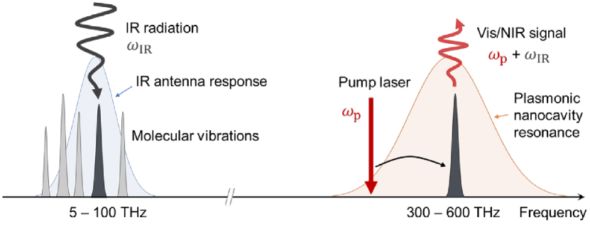 \SetHorizontalCoffin\labelcoffin(b)\SetVerticalPole\imagecoffinleft3pt+\CoffinWidth\labelcoffin/2\SetVerticalPole\imagecoffinright\Width-3pt-\CoffinWidth\labelcoffin/2\SetHorizontalPole\imagecoffinup\Height-4pt-\CoffinHeight\labelcoffin/2\SetHorizontalPole\imagecoffindown3pt+\CoffinHeight\labelcoffin/2\JoinCoffins\imagecoffin[left,up]\labelcoffin[vc,hc]\TypesetCoffin\imagecoffin
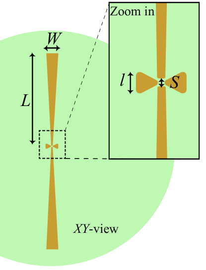
As pictured in Fig. 1, we employ a second antenna resonant at (a frequency in the VIS-NIR domain, which we call “optical” domain from here on for brevity), whose decay rates are defined in the same way as the IR antenna parameters. The optical antenna enhances the parametric optomechanical interaction of the molecular vibration with a pump laser in the optical domain, as described in Ref. roelli_molecular_2016. Concisely the interaction between an optical field and molecular oscillators leads to a dispersive interaction described by the Hamiltonian with the collective optomechanical vacuum coupling rate and the optical pump field bosonic ladder operators (the vibrational phononic operators at frequency ). The number of molecules participating in the optomechanical interaction with the pump laser may be different from the number participating to IR absorption, as elaborated in Sec. III below (cf. also Appendix D Sec. 5,6).
The optical antenna field can be split into an average coherent amplitude and a fluctuating term so that . Expanding to first order in the optomechanical interaction we obtain the linearized interaction
| (3) |
with the mean occupation of the optical antenna mode (see Appendix A).
The spectral density of the output field on the optical port in [photons/(Hzs)] can be evaluated through the calculation of the two-time correlations of the optical output field operators wilson-rae_cavity-assisted_2008; scully_quantum_1997:
| (4) |
Following previous works in optomechanics schliesser2010cavity and their extension to molecular optomechanics schmidt_quantum_2016; schmidt_linking_2017 we can write an analytical expression of the outgoing spectral density at the anti-Stokes sideband (at the Stokes sideband ) with the mean final phonon number of the vibrational mode. Due to the IR and optomechanical interactions the intrinsic vibrational damping rate is modified with the IR antenna-assisted damping rate and the additional damping rate of electromagnetic origin characterized by the imbalance between the optical antenna-assisted transition rates to the ground and excited vibrational states (see Appendix A).
The final phonon number in the vibrational mode, , is given by the expression wilson-rae_cavity-assisted_2008
| (5) |
where is the total phonon number in the absence of optical drive. It is the incoherent sum of the IR-induced vibrational excitation (Eq. 2) and the thermal noise, for a bath temperature . We assume here that the pump laser does not lead to significant Ohmic heating of the system. It is however straightforward to model laser-induced heating by introducing a pump-power-dependent bath temperature .
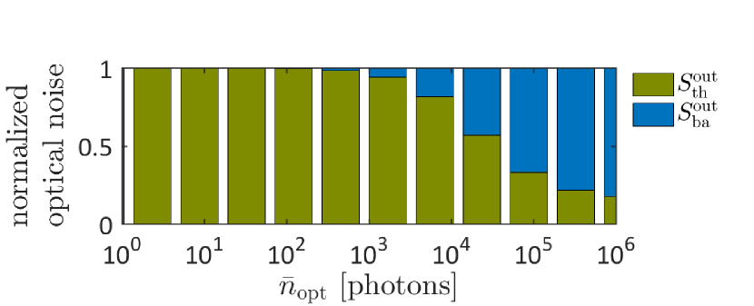
The resulting spectral density in the absence of incoming IR radiation () should be integrated over the device’s operational bandwidth () to obtain its dark-count rate . The dark-count rate arising from the thermal contribution to the first term in Eq. (5) can be reduced by cooling the bath, whereas the second term describes a minimal noise level resulting from phonon creation by spontaneous Stokes scattering of the pump laser, a process equivalent to quantum backaction in cavity optomechanics. Therefore an optimal power that maximizes the signal-to-noise ratio (SNR) exists, akin to the standard quantum limit (SQL) in position measurements.
From these expressions we are also able to describe the conversion efficiency from an incoming rate of IR photons coupled to the antenna into an outgoing rate of optical photons emitted by the antenna into free space, as where is an external conversion efficiency 111In this expression, we did not include the frequency dependence of the photonic density of state in free space, nor the factors related to the specific optical design used to couple light in and out of the structure. with .
The internal conversion efficiency can in turn be divided into a power-dependent part and a part describing the spatial overlap between the IR near field, the optical near field and the molecular ensemble, which we write . To approximate this last term we factorize it into two contributions: the spatial overlap between the IR and optical near fields () and the vectorial overlap between the near-field polarization (typically normal to the antenna surface) and the molecular orientation, which we name ; so that we can write
| (6) |
The evaluation of is detailed in Appendix D (Sec. 5,6). The power and detuning dependence of the optomechanical efficiency term are depicted in Fig. 3 (b) and its exact calculation is given in Appendix A.
III Molecular transducer
The electric dipole moment and polarizability of a vibrational mode can be extracted from experimental data of resonant light absorption and inelastic light scattering, respectively herzberg_molecular_1960; colthup_introduction_1990.
\SetHorizontalCoffin\imagecoffin \SetHorizontalCoffin\labelcoffin(a)\SetVerticalPole\imagecoffinleft3pt+\CoffinWidth\labelcoffin/2\SetVerticalPole\imagecoffinright\Width-3pt-\CoffinWidth\labelcoffin/2\SetHorizontalPole\imagecoffinup\Height-4pt-\CoffinHeight\labelcoffin/2\SetHorizontalPole\imagecoffindown3pt+\CoffinHeight\labelcoffin/2\JoinCoffins\imagecoffin[left,up]\labelcoffin[vc,hc]\TypesetCoffin\imagecoffin
\SetHorizontalCoffin\imagecoffin
\SetHorizontalCoffin\labelcoffin(a)\SetVerticalPole\imagecoffinleft3pt+\CoffinWidth\labelcoffin/2\SetVerticalPole\imagecoffinright\Width-3pt-\CoffinWidth\labelcoffin/2\SetHorizontalPole\imagecoffinup\Height-4pt-\CoffinHeight\labelcoffin/2\SetHorizontalPole\imagecoffindown3pt+\CoffinHeight\labelcoffin/2\JoinCoffins\imagecoffin[left,up]\labelcoffin[vc,hc]\TypesetCoffin\imagecoffin
\SetHorizontalCoffin\imagecoffin \SetHorizontalCoffin\labelcoffin(b)\SetVerticalPole\imagecoffinleft3pt+\CoffinWidth\labelcoffin/2\SetVerticalPole\imagecoffinright\Width-3pt-\CoffinWidth\labelcoffin/2\SetHorizontalPole\imagecoffinup\Height-4pt-\CoffinHeight\labelcoffin/2\SetHorizontalPole\imagecoffindown3pt+\CoffinHeight\labelcoffin/2\JoinCoffins\imagecoffin[left,up]\labelcoffin[vc,hc]\TypesetCoffin\imagecoffin
For vibrational modes lacking centrosymmetry the derivatives of both quantities with respect to the displacement coordinate can be nonvanishing wilson_molecular_1980. We show such a situation in Fig. 2 where we plot the projections of the derivatives of the electric moment and of the polarizability with respect to the molecular coordinate of the mode of thiophenol, which we choose as an example in our calculations. We note that the projection of the tensor onto an axis perpendicular to the principal axis of the electronic moment derivative can be nonvanishing. Several polarization directions for in- and outcoupling of resonant and up-converted fields are thus conceivable.
The calculations leading to the parametric optomechanical vacuum coupling rate between the antenna field and the vibrational mode has been previously described roelli_molecular_2016 and its value is given by with the polarizability tensor, the reduced displacement coordinate of the vibrational mode labeled by , the optical mode volume and the unit polarization vector of the optical antenna mode.
The coupling rate associated with a vibrational mode is linked to an effective transition dipole that can be numerically computed using e.g. density functional theory (DFT; cf. Appendix D). Its value is where the electric field per photon is given by with the mode volume and the unit polarization vector of the IR mode scully_quantum_1997; haroche_exploring_2006.
Since scales with , it can be independent of the mode volume as long as this volume is filled with molecules. On the contrary the interaction of the vibration with the VIS-NIR optical field scales as advocating for a device confining strongly this field, thereby reducing the optical power required to reach an efficient conversion process.
IV Dual plasmonic antenna
Nanoantennas have proven to be instrumental in enhancing the interaction of molecules with off-resonant VIS-NIR optical fields (e.g. for surface-enhanced Raman scattering, SERS) zhu_quantum_2014; benz_single-molecule_2016 and resonant IR fields (e.g. for surface-enhanced infrared absorption, SEIRA) brown_fan-shaped_2015; neubrech_surface-enhanced_2017. We now present the design of a new dual-resonant antenna (see Figs. 1 and 2) and compute the interaction of the local fields at the VIS-NIR and IR resonances with a specific vibrational mode of an ensemble of molecules covering the nanostructure. We assume that molecules are attached with their main axis perpendicular to the metallic surfaces, and extract from DFT calculations the relevant components of the derivatives of the electronic moment and polarizability with respect to the normal mode coordinate. We note that calculations for specific self-assembled monolayer orientations schreiber_structure_2000; love_self-assembled_2005 or randomly oriented molecules can be achieved from the full knowledge of and .
In our design the incoming field (to be up-converted) and the pump laser field are each resonant with a different component of the antennas arranged in a crossed configuration (cf. Appendix E for additional information on the design and values of its parameters). At their intersection, the near-field polarizations of the two fields are collinear (), and we obtain % for the vibrational mode illustrated in Fig. 2, when accounting for the specificities of the corresponding Raman tensor and IR transition dipole. Electromagnetic simulations demonstrate that the two fields, despite differing in frequency by more than one order of magnitude in that particular example, are confined within a very similar volume inside the nanogaps separating the two structures. This results in a spatial overlap of the two main electromagnetic field components within the dual antenna reaching %.
From our numerical calculations we find that the antenna-assisted IR coupling rate for the vibrational mode at wavenumber reaches GHz as is decreased by several orders of magnitude below its diffraction limit (the calculation of and are detailed in Appendix C). As the cavity damping rate remains larger than the collective vacuum IR coupling rate ( — Purcell regime) the antenna-enhanced damping rate for this vibrational mode can be approximated by the expression haroche_exploring_2006 : .
We compute in Appendix D the coupling rate of another vibrational mode that has a larger IR dipole moment: Under optimal molecular orientation and filling conditions, that mode is at the onset of the collective strong coupling regime with the IR antenna mode shalabney_coherent_2015. While future work is needed to properly describe this regime in the context of wavelength conversion, we note that our design offers new perspectives to realize a source of IR photons. Indeed, in the strong coupling regime and under optomechanical parametric amplification roelli_molecular_2016, the optically pumped population is shared between the collective vibrational mode and the corresponding IR antenna mode, resulting in the fast emission of IR radiation.
V Optical noise contributions
 \SetHorizontalCoffin\labelcoffin
(a) \SetVerticalPole\imagecoffinleft3pt+\CoffinWidth\labelcoffin/2\SetVerticalPole\imagecoffinright\Width-3pt-\CoffinWidth\labelcoffin/2\SetHorizontalPole\imagecoffinup\Height-4pt-\CoffinHeight\labelcoffin/2\SetHorizontalPole\imagecoffindown3pt+\CoffinHeight\labelcoffin/2\JoinCoffins\imagecoffin[left,up]\labelcoffin[vc,hc]\TypesetCoffin\imagecoffin
(b) \SetVerticalPole\imagecoffinleft3pt+\CoffinWidth\labelcoffin/2\SetVerticalPole\imagecoffinright\Width-3pt-\CoffinWidth\labelcoffin/2\SetHorizontalPole\imagecoffinup\Height-4pt-\CoffinHeight\labelcoffin/2\SetHorizontalPole\imagecoffindown3pt+\CoffinHeight\labelcoffin/2\JoinCoffins\imagecoffin[left,up]\labelcoffin[vc,hc]\TypesetCoffin\imagecoffin
 \SetHorizontalCoffin\labelcoffin
(c)\SetVerticalPole\imagecoffinleft3pt+\CoffinWidth\labelcoffin/2\SetVerticalPole\imagecoffinright\Width-3pt-\CoffinWidth\labelcoffin/2\SetHorizontalPole\imagecoffinup\Height-4pt-\CoffinHeight\labelcoffin/2\SetHorizontalPole\imagecoffindown3pt+\CoffinHeight\labelcoffin/2\JoinCoffins\imagecoffin[left,up]\labelcoffin[vc,hc]\TypesetCoffin\imagecoffin
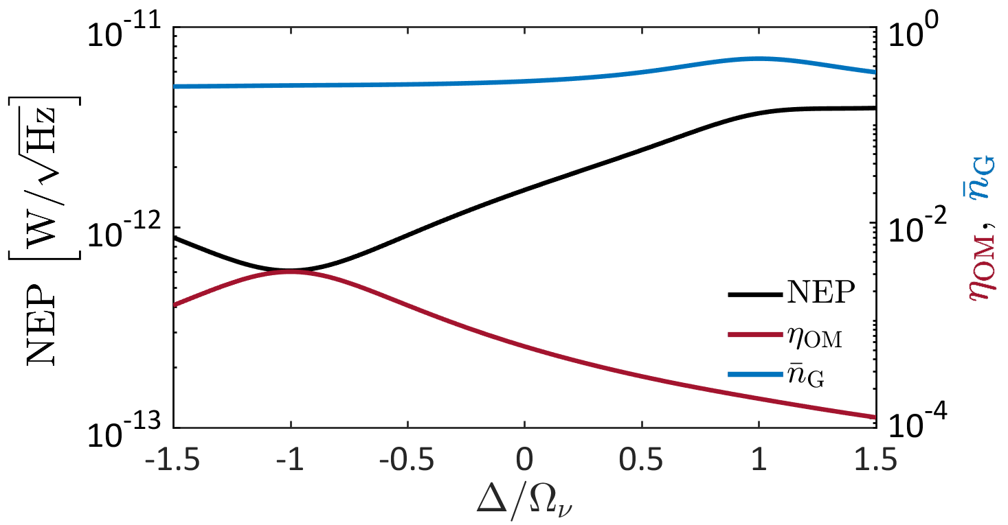
A useful figure of merit to compare the performance of detectors independently of their respective operational bandwidth is the noise-equivalent power, where is the incoming power at which the detector reaches a unity signal-to-noise ratio (SNR). This definition can be translated to a our converter by defining the SNR as . If we assume that the dark noise of a detector in the VIS-NIR range is negligible compared to the up-conversion noise, the NEP of the converter is by extension that of a detector built upon it. We show the computed NEP in Fig. 3 as a function of the optical pump power and laser detuning from the cavity resonance. Remarkably, the NEP reaches values that improve on the state of the art for uncooled commercial devices (Table 1) and compares favorably with more recently demonstrated room-temperature platforms long_room_2017; chen_widely_2017 operating at the higher end of the frequency range achievable with our molecular up-converter.
| Detector type | NEP |
|---|---|
| Golay cell | |
| Pyroelectric | |
| MCT photodiode | |
| Microbolometer | |
| Molecular device |
When operating with a pump laser red-detuned from the optical resonance in the resolved sideband regime we can simplify the interaction of Eq. 3 and obtain
| (7) |
This regime provides maximal efficiency and optimal NEP, as seen in Fig. 3(a). We note that for low-frequency vibrational modes the condition could be achieved with the help of hybrid cavities that feature narrower linewidths doeleman_antennacavity_2016; gurlek_manipulation_2018.
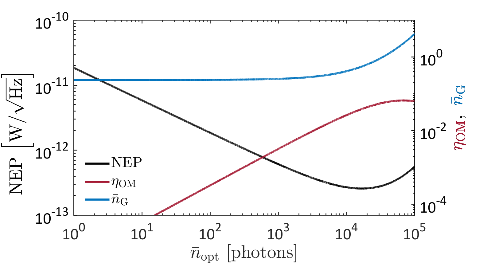
Keeping this optimal detuning, we investigate in Fig. 3(b) how the NEP depends on optical pump power. As the intracavity pump photon number is increased, the efficiency initially grows linearly, while the noise remains constant, limited by the thermally generated anti-Stokes signal. This yields a square-root decrease of NEP with pump power. Interestingly, at high intracavity photon number the contribution of optomechanical quantum backaction to the dark-count rate surpasses the thermal contribution, and the NEP degrades with increasing power. This behavior is reminiscent of the standard quantum limit for displacement detection in optomechanical cavities.
Another unique feature of the up-conversion scheme is its compatibility with single-photon detectors already available in the VIS-NIR range. To assess more precisely the feasibility of operating our device in single-photon counting mode, we introduce the noise-equivalent photon rate, i.e. . This quantity corresponds to the incoming IR photon rate at the input of the device that would generate an output rate of up-converted photons equal to the dark-count rate.
In practice, noisy single-photon detectors are best operated in gated mode. In our approach, this mode is easily realized using a pulsed optical pump laser, with a pulse duration of a few picoseconds that ideally matches the molecular vibrational linewidth; . This mode of operation provides not only better noise rejection and higher intracavity photon numbers (therefore better efficiency), but also ultrafast timing resolution that is not otherwise achievable due to the intrinsic timing jitter of VIS-NIR single-photon counters (typically several tens of picoseconds) hadfield_single-photon_2009. We therefore define the noise-equivalent photon number per gate which translates the noise-equivalent photon rate into an average incoming IR noise photons per time gate.
VI Converter Arrays
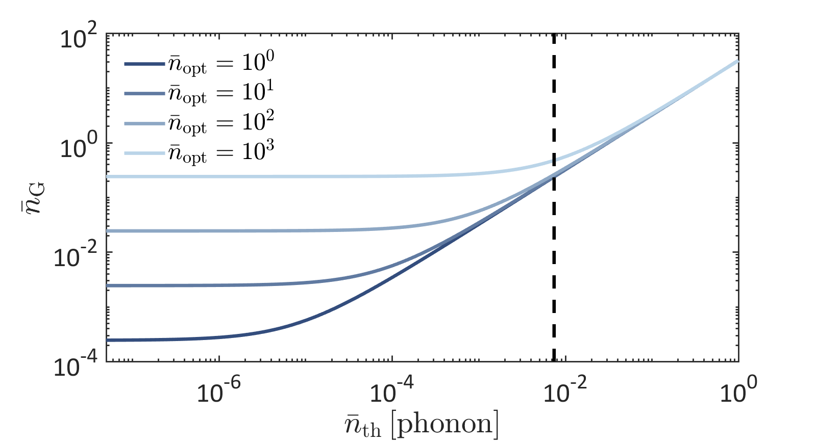
To gain more insight on the limiting factors constraining single-photon operation, we plot as a function of the thermal occupancy of the vibration and of the intracavity pump photon number in Fig. 3(c). This graph shows that moderate cooling of the device to 100∘C below ambient (achieved with thermoelectric cooling systems) would bring the thermal occupancy of this vibrational mode down to allowing to reach a noise as low as , making single-photon counting with picosecond time resolution in the MIR and FIR domains a realistic prospect. For the lower-frequency range (5–20 THz) reducing the temperature of the molecules in a cryogenic environment would be required to allow single-photon operation.
A promising way to further reduce the gated dark-count level consists in designing an array of molecular converters, sufficiently distant from each other so as not to interact by near-field coupling. We assume that the array is illuminated by spatially coherent IR signal and optical pump beam, which is achievable when using a high -number lens due to the sub-wavelength dimensions of the antennas. The key advantage of this scheme is that the anti-Stokes fields of thermal origin from different antennas would not exhibit any mutual phase coherence; they will add up incoherently in the far field. On the contrary, the up-converted (sum-frequency) anti-Stokes fields would be phase coherent and interfere constructively in specific directions, in analogy with a phased emitter array dregely_3d_2011; busschaert_beam_2019. Considering a simple linear array, as demonstrated in Appendix F, this effect would jointly decrease the thermal contribution to the dark-count rate and dilute the intracavity photon number per device, enabling single-photon operation with improved sensitivity.
A configuration with multiple converters within the IR spot
could alternatively be leveraged for on-chip IR multiplexing
schwarz_monolithically_2014; lin_mid-infrared_2018; tittl_imaging-based_2018; yesilkoy_ultrasensitive_2019
with distinct converters responding to distinct IR frequencies by the proper choice of molecular vibrations and antenna design, thereby bypassing the limited detection bandwidth of a single converter.
This sub-wavelength platform benefits from the coherent nature of the conversion process and opens the route to IR spectroscopy, IR hyperspectral imaging and recognition technologies.
VII Conclusion
In summary, we presented a new concept for frequency upconversion from the mid-infrared to the visible domain based on the interaction of both fields with molecular vibrations coupled to a dual-resonant nanoantenna. We considered an incoming long-wavelength infrared radiation that resonantly excites a vibrational mode, which is simultaneously coupled through its Raman polarizability to a coherent pump field at shorter wavelength (visible or near-infrared), resulting in up-conversion of the IR signal onto the anti-Stokes sideband of the pump. Thanks to the recently developed framework of molecular cavity optomechanics, we were able to treat the problem in a full quantum model, and thereby predict the internal quantum efficiency of our device, as well as its outgoing noise spectral density. We showed that the noise added in the conversion process has two main origins: thermal noise and backaction noise (including quantum and dynamical backaction), the latter increasing superlinearly with pump power and eventually becoming dominant. We analyzed the dependence of the noise-equivalent power (NEP)on the intracavity pump photon number and pump-cavity detuning, and predicted that under the optimal condition of red-sideband excitation, the NEP can be as low as few , improving on the state of the art for devices operating at ambient conditions.
We stress that our numerical estimates are based on a realistic nanoantenna design and a common simple molecule (thiophenol). Although the intracavity photon numbers required to reach optimal performance appear to be large, they can be achieved under pulsed excitation albrecht2017. Moreover requirements on the intracavity power would be lowered by further reducing the gap size (down to 1–2 nm) and by chemical engineering of the molecular converter toward higher Raman activity. Our study also shows that by moderately increasing the resonant coupling rate between molecular vibration and IR antenna, the system would enter the IR strong coupling regime, with the formation of vibrational polaritons shalabney_coherent_2015. We leave the study of the conversion process in this new regime for future investigation.
Acknowledgements
The authors thank Wen Chen and the reviewers of the article for valuable comments.
C. G. acknowledges support from the Swiss National Science Foundation
through Grant No. PP00P2-170684.
This work has received funding from the European Union’s Horizon 2020 research and innovation programme with grant agreement No. 732894 (HOT) and No. 829067 (THOR).
P. R. acknowledges support from the Max Planck-EPFL Center for Molecular Nanoscience and Technology.
D. M.-C. thanks Vahid Sandoghdar and acknowledges financial support from the Max Planck Society.
Appendix A Optomechanical framework
A detailed description of the optomechanical framework
can be found elsewhere
schliesser2010cavity; roelli_molecular_2016; schmidt_quantum_2016; schmidt_linking_2017. Here we just remind the readers of the few definitions
and relationships used in the paper.
The average number of intracavity excitations in the VIS-NIR (label ‘opt’) or IR antenna mode is related to the incoming photon flux and incoming power by
| (8) |
When considering the molecular vibrational levels and their parametric coupling to the optical field, the antenna-assisted transition rate to a lower excited level (anti-Stokes transition) is given by
| (9) |
The antenna-assisted transition rate to a higher excited vibrational level (Stokes transition) is given by
| (10) |
The interested reader can find the complete derivation of the outgoing spectral density in Ref. wilson-rae_cavity-assisted_2008. In this manuscript we are interested in the signal arising on the anti-Stokes sideband. Starting from Eq. (4) in the main text and following the same calculation steps we arrive at the final expression
| (11) |
For convenience we label the different components of the outgoing noise spectral density according to the origin of the vibrational population from which they result (cf. Eq. (5) in the main text):
| (12) |
With this notation the total noise quanta in the outgoing optical field is
.
We can then derive the expression for the conversion efficiency defined as
and obtain
| (13) |
This expression comprises the different factors constituting Eq. (6) of the main text.
For a pump field red-detuned from the optical antenna resonance () this expression can be further developed to evidence the dependence of the internal conversion efficiency on IR and optical collective vacuum coupling rates:
| (14) |
Using this conversion efficiency, we have an alternate way to calculate the NEP directly from the dark-count rate and efficiency of the device as hadfield_single-photon_2009. This method gives identical results as the one presented in the main text.
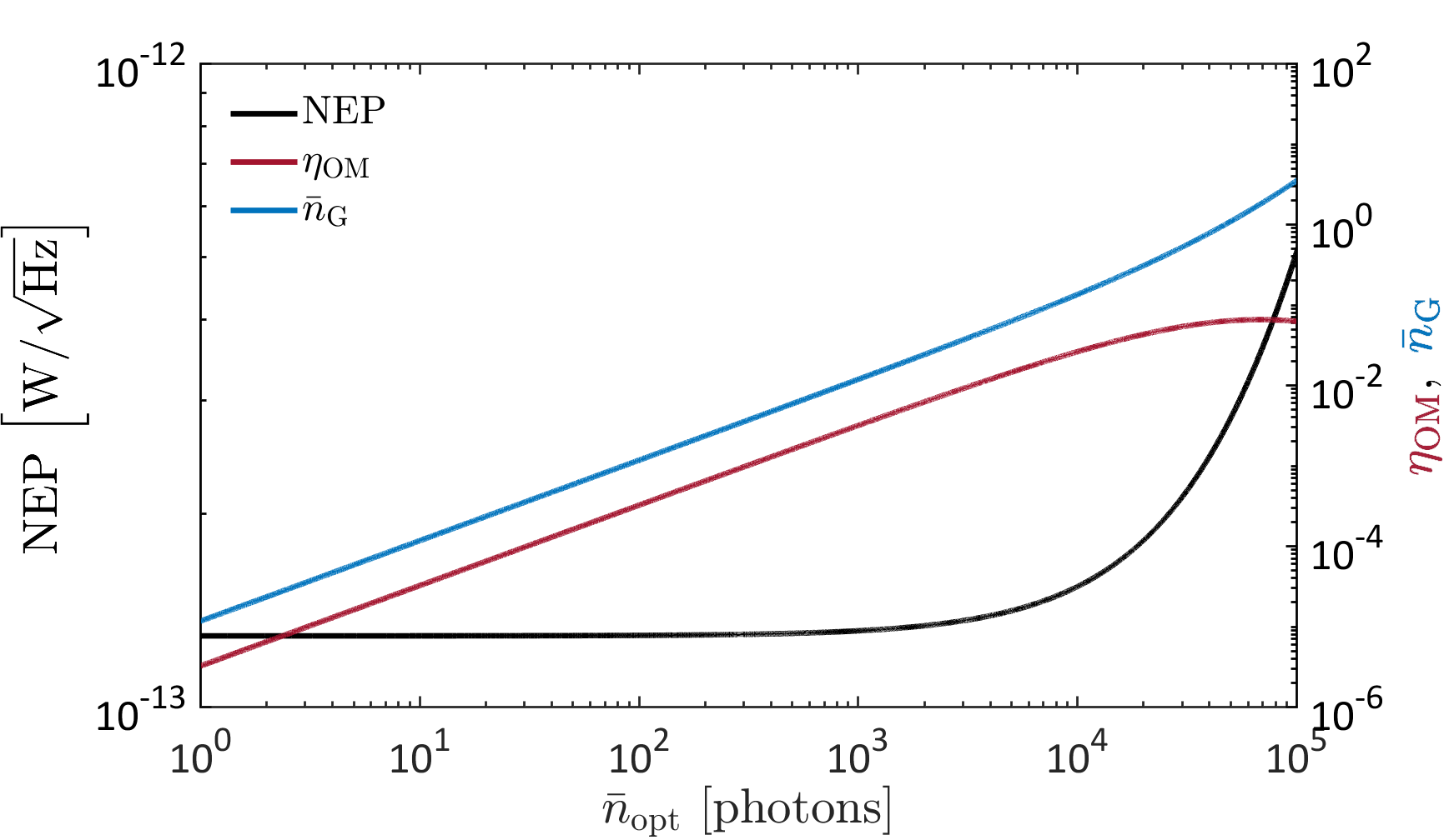
In Fig. 4 we show the computed conversion efficiency and NEP for the case . In this red-detuned configuration our model assumptions remain valid for a large range of optical intracavity photon numbers. At high optical power we observe that the efficiency and the NEP reach an extremal value when the backaction contribution to the outgoing noise equals that of thermal vibrations.
In Fig. 4b,c we also show how these extremal points move when changing the IR absorption cross-section (in b) or Raman activity (in c) of the molecules. As can be expected, improving the Raman activity of the molecules only displaces the curves to the left without modifying the extremal values – meaning that lower optical pump power is required to reach the same NEP and conversion efficiency. In contrast, improving the IR absorption can lead to a lower achievable NEP, in a certain range. For too large IR cross-sections, the vibration starts to enter the strong coupling regime with the IR antenna, and a different treatment would be needed to provide accurate predictions.
(a)\SetVerticalPole\imagecoffinleft3pt+\CoffinWidth\labelcoffin/2\SetVerticalPole\imagecoffinright\Width-3pt-\CoffinWidth\labelcoffin/2\SetHorizontalPole\imagecoffinup\Height-4pt-\CoffinHeight\labelcoffin/2\SetHorizontalPole\imagecoffindown3pt+\CoffinHeight\labelcoffin/2\JoinCoffins\imagecoffin[left,up]\labelcoffin[vc,hc]\TypesetCoffin\imagecoffin
\SetHorizontalCoffin\imagecoffin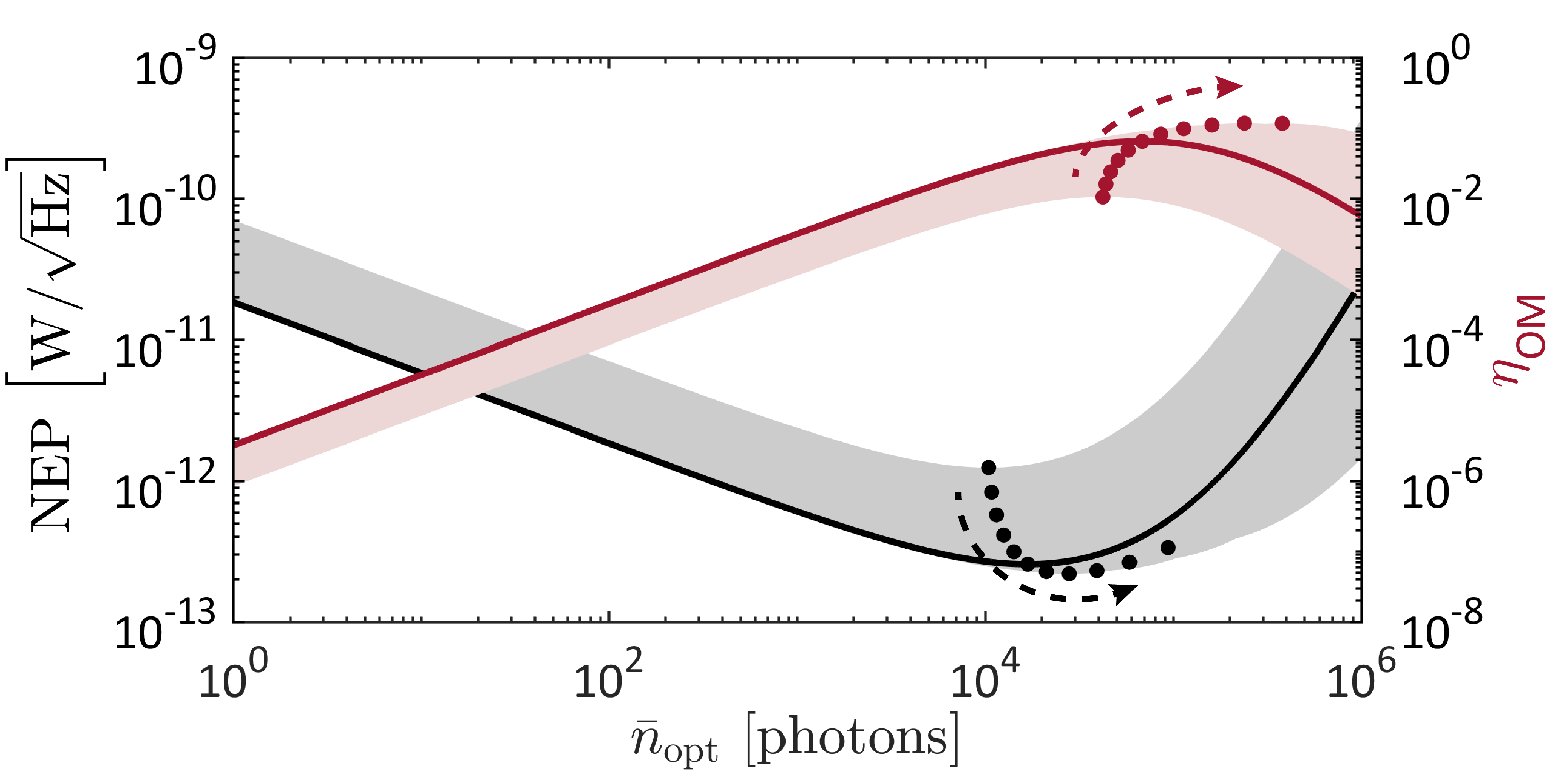 \SetHorizontalCoffin\labelcoffin(b)\SetVerticalPole\imagecoffinleft3pt+\CoffinWidth\labelcoffin/2\SetVerticalPole\imagecoffinright\Width-3pt-\CoffinWidth\labelcoffin/2\SetHorizontalPole\imagecoffinup\Height-4pt-\CoffinHeight\labelcoffin/2\SetHorizontalPole\imagecoffindown3pt+\CoffinHeight\labelcoffin/2\JoinCoffins\imagecoffin[left,up]\labelcoffin[vc,hc]\TypesetCoffin\imagecoffin
\SetHorizontalCoffin\imagecoffin
\SetHorizontalCoffin\labelcoffin(b)\SetVerticalPole\imagecoffinleft3pt+\CoffinWidth\labelcoffin/2\SetVerticalPole\imagecoffinright\Width-3pt-\CoffinWidth\labelcoffin/2\SetHorizontalPole\imagecoffinup\Height-4pt-\CoffinHeight\labelcoffin/2\SetHorizontalPole\imagecoffindown3pt+\CoffinHeight\labelcoffin/2\JoinCoffins\imagecoffin[left,up]\labelcoffin[vc,hc]\TypesetCoffin\imagecoffin
\SetHorizontalCoffin\imagecoffin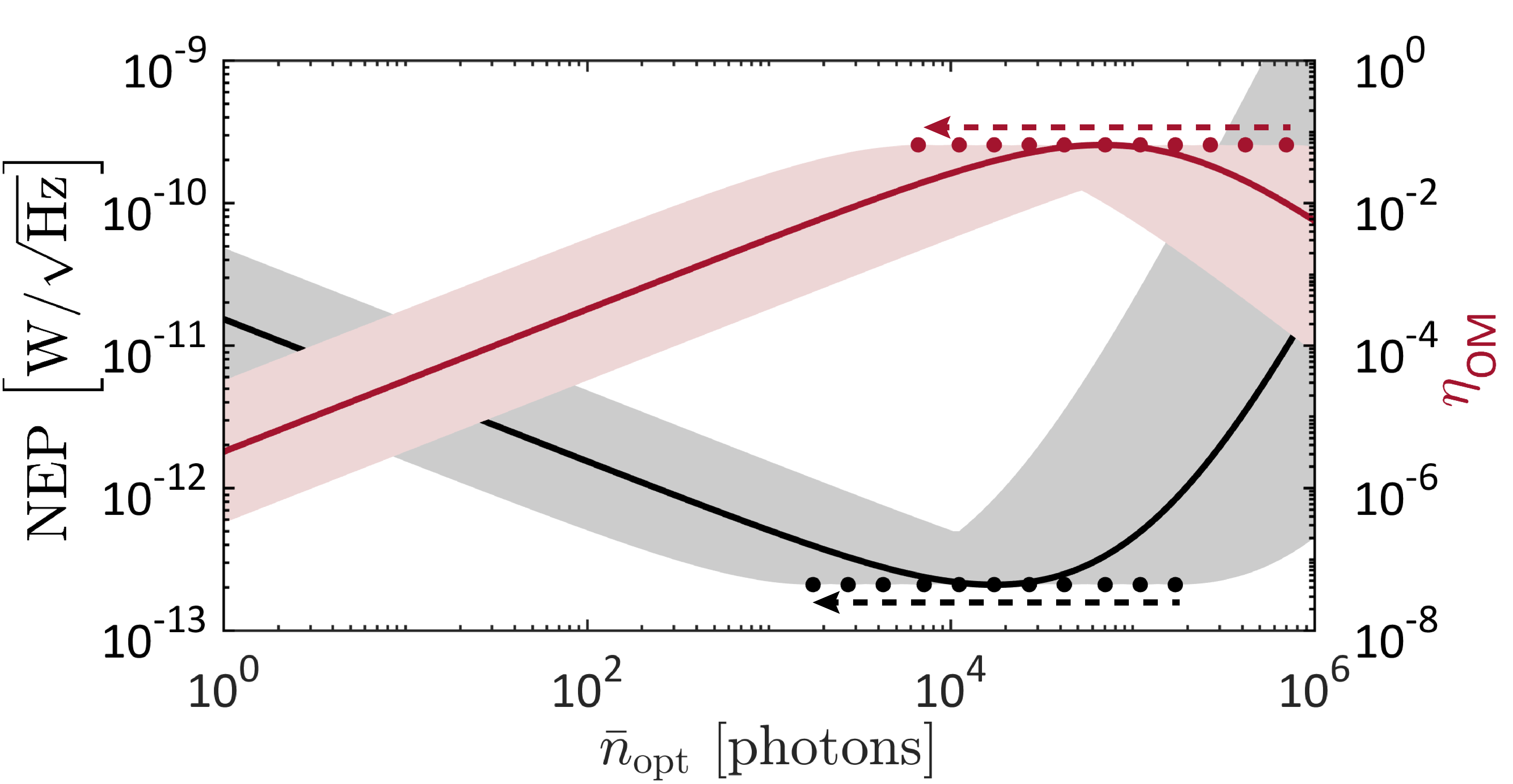 \SetHorizontalCoffin\labelcoffin(c)\SetVerticalPole\imagecoffinleft3pt+\CoffinWidth\labelcoffin/2\SetVerticalPole\imagecoffinright\Width-3pt-\CoffinWidth\labelcoffin/2\SetHorizontalPole\imagecoffinup\Height-4pt-\CoffinHeight\labelcoffin/2\SetHorizontalPole\imagecoffindown3pt+\CoffinHeight\labelcoffin/2\JoinCoffins\imagecoffin[left,up]\labelcoffin[vc,hc]\TypesetCoffin\imagecoffin
Appendix B Zero-temperature limit
The limit of vanishing thermal occupancy of the vibrational mode is relevant for specific applications, and it demonstrates how the backaction noise acting onto the vibration sets a fundamental lower bound on the achievable NEP of the converter. When () the outgoing noise spectral density of eq. (12) can be simplified to
| (15) |
Taking into account eq. (13) for the expression of the external conversion efficiency, the NEP and the at 0 K can be calculated.
In the regime of weak optical pumping, , we obtain a linear scaling of as a function of the intracavity photon number (appearing in the transition rates and ) while the NEP remains constant (cf. Fig. 5). The value of the NEP at this plateau, which corresponds to an intrinsic quantum limit due to measurement backaction, is given by the following expression
| (16) |
Appendix C Absorption of incoming IR radiation by molecular vibration
We describe in the following the coupling between a resonant field and a single molecular oscillator inside a cavity (i.e. antenna). We also derive the expression given in the main text for the number of excited phonons in the steady state. Our treatment is inspired by that of Ref. cohen-tannoudji_atom-photon_1992.
The interaction between an external monochromatic field of frequency and the molecular vibration inside a cavity is given in the dipole approximation by
| (17) |
where with the phase offset between the field and the dipole, an adjustable phase parameter of the driving field. is the vacuum field, with the mode volume and the unit polarization vector of the IR mode.
This interaction can be written in terms of the bosonic ladder operators describing the IR mode inside the cavity and the vibrational phononic operators at frequency . For a weak IR drive the vibrational Hilbert space of each molecule can be reduced to ground and first excited state and described like a two level system (TLS) with creation and annihilation operators scully_quantum_1997. We note that the validity of the TLS description for a collective vibrational mode of oscillators would break down only for a number of excitations of order haroche_exploring_2006.
The dipolar transition is purely off-diagonal in this basis and described as . The field inside the cavity is in turn described by haroche_exploring_2006. In a frame rotating at the frequency of the IR driving field and keeping only the resonant processes () we obtain the interaction Hamiltonian :
| (18) |
with .
Here we choose the additional phase term of the driving field
in order for the coupling to be real positive, without loss of generality.
We follow the dynamics of the TLS in this rotating frame. Introducing the rate which describes the total damping of the vibrational mode as described in the main text, we obtain
| (19a) | ||||
| (19b) | ||||
| (19c) | ||||
| (19d) | ||||
with the detuning between the IR drive
and the vibrational resonance.
These equations are often described with the help of the Bloch vector components:
| (20a) | ||||
| (20b) | ||||
| (20c) | ||||
The components of the Bloch vectors are related to the average dipole value cohen-tannoudji_atom-photon_1992: . We derive the master equations as a function of these components:
| (21a) | ||||
| (21b) | ||||
| (21c) | ||||
The steady-state solutions of these equations are
| (22a) | ||||
| (22b) | ||||
| (22c) | ||||
The average number of photons absorbed per unit time by the vibrational dipole is given by
| (23) |
If the detuning and coupling are much smaller than the vibrational damping rate (), the average number of absorptions over an IR period can be written as
| (24) |
In the steady state the rate of photons absorbed by the vibrational mode equals the phonon damping rate so that the average number of excited phonons is
| (25) |
The condition is satisfied in realistic scenarios since the IR antenna decay rate is typically faster than the vibrational damping rate . We note that the average number of excited phonons can also be simply derived from the steady-state population of the upper TLS state .
Appendix D Simulation of molecular parameters
The infrared absorption intensity of fundamental vibrational transitions can be obtained by DFT calculations wilson_molecular_1980; feugmo_analyzing_2013 of the derivatives of the electric moment components with respect to the normal coordinates representing the vibrational mode of interest. They are usually expressed in [kmmol-1]. For a non-degenerate and harmonic vibrational mode the absorption intensity averaged over all orientations is given by
| (26) |
with the Avogadro number.
D.1 Gaussian calculations
The procedure is well described in the context of Raman calculations in the book of Le Ru & Etchegoin ru_principles_2008. The Gaussian software gives access to the derivatives of the electric dipole with respect to the ith component of the displacement in Cartesian coordinates of the nth atom. These derivatives can then be converted to derivatives with respect to the normal coordinates of a vibrational mode and are given in atomic units, i.e. the electric moment is given in bohr-electron (2.54 D / Cm) and the displacement in bohr (0.529 Å). The quantities can be converted to other systems of units:
| (27) |
and finally linked to the absorption intensity of an incoming field of polarization
| (28) |
| Mode | Coverage | ||||
|---|---|---|---|---|---|
| mode 1002 | 0.52 (0.51) | 2.40 (0.96) | 0.33 (0.14) | monolayer | 0.01 |
| volume | 0.06 | ||||
| mode 1093 | 86.95 (28.52) | 0.85 (0.31) | 0.97 (0.18) | monolayer | 0.17 |
| volume | 0.75 |
D.2 Cross-section
This expression can be linked to the absorption cross-section . If we assume a Lorentzian profile for the transition considered, the on-resonance value of the cross-section is .
Thus, the absorption cross-section can be inferred from DFT calculations:
| (29) |
D.3 Effective dipole moment
Accordingly we can also describe an effective dipole moment to characterize the vibrational transition and link it explicitly to the electronic moment derivatives found in DFT calculations:
| (30) |
D.4 Raman activity of an ensemble of molecules
We refer the interested reader to Refs. ru_principles_2008; roelli_molecular_2016 for detailed descriptions of the Raman activity, its connection with the optomechanical coupling rate and its calculation through DFT. For completeness we reproduce here a few expressions of the tensorial quantity averaged over randomly oriented molecules. To simplify the notation we introduce the Raman tensor and we refer to the scalar as . Taking and averaging over random orientations of the molecules one can obtain
| (31) | ||||
| (32) |
with and . These quantities do not depend on the two orthogonal orientations of the field chosen as polarization basis but only on the intrinsic properties of the molecule. In that situation Raman scattering can be described by a scalar named the magnitude of the Raman tensor and can be derived directly from DFT calculations.
We also introduce the depolarization ratio that evaluates the importance of the cross-polarized component of the Raman-scattered field (with respect to the incoming field) and that is bounded by . In the SERS scenario the outgoing field is solely polarized along the direction of the local cavity field . For randomly oriented molecules the magnitude of the Raman tensor is thus rescaled by a factor dependent on the depolarization ratio:
| (33) |
D.5 Local overlap -
The factor describes the local overlap between the two fields involved in our conversion scheme, on the one hand, and the IR dipole and Raman tensor of the molecular vibration, on the other hand. It is defined in the following way:
| (34) |
with the label designating the direction of the near field at the location of the molecule. To compute (see Table 2) we numerically average over all possible orientations of the molecule, while keeping the IR and optical local field collinear.
D.6 Orientation and number of molecules contributing to the IR/optical process
From the DFT calculations we compute the molecular parameters
for several cases of interest and report their values in Table 2.
Two orientations (main axis of the molecule parallel to both local fields or fully random molecular orientation) are considered.
Two options are also considered for the coverage: one monolayer covering the planar parts of the
metallic nanostructure or a superposition of layers filling the entire volume
where the fields are localized. We use the IR/optical mode volumes
(given below), the molar mass ( kg/mol), volume density ( kg/m3)
or surface density ( m-2) of thiophenol
to estimate the number () of molecules participating in the IR (optical) process.
Appendix E Numerical simulation of the antenna’s optical response
 \SetHorizontalCoffin\labelcoffin
(a)\SetVerticalPole\imagecoffinleft3pt+\CoffinWidth\labelcoffin/2\SetVerticalPole\imagecoffinright\Width-3pt-\CoffinWidth\labelcoffin/2\SetHorizontalPole\imagecoffinup\Height-4pt-\CoffinHeight\labelcoffin/2\SetHorizontalPole\imagecoffindown3pt+\CoffinHeight\labelcoffin/2\JoinCoffins\imagecoffin[left,up]\labelcoffin[vc,hc]\TypesetCoffin\imagecoffin
\SetHorizontalCoffin\imagecoffin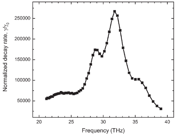 \SetHorizontalCoffin\labelcoffin(b)\SetVerticalPole\imagecoffinleft3pt+\CoffinWidth\labelcoffin/2\SetVerticalPole\imagecoffinright\Width-3pt-\CoffinWidth\labelcoffin/2\SetHorizontalPole\imagecoffinup\Height-4pt-\CoffinHeight\labelcoffin/2\SetHorizontalPole\imagecoffindown3pt+\CoffinHeight\labelcoffin/2\JoinCoffins\imagecoffin[left,up]\labelcoffin[vc,hc]\TypesetCoffin\imagecoffin
\SetHorizontalCoffin\imagecoffin
\SetHorizontalCoffin\labelcoffin(b)\SetVerticalPole\imagecoffinleft3pt+\CoffinWidth\labelcoffin/2\SetVerticalPole\imagecoffinright\Width-3pt-\CoffinWidth\labelcoffin/2\SetHorizontalPole\imagecoffinup\Height-4pt-\CoffinHeight\labelcoffin/2\SetHorizontalPole\imagecoffindown3pt+\CoffinHeight\labelcoffin/2\JoinCoffins\imagecoffin[left,up]\labelcoffin[vc,hc]\TypesetCoffin\imagecoffin
\SetHorizontalCoffin\imagecoffin \SetHorizontalCoffin\labelcoffin (c)\SetVerticalPole\imagecoffinleft3pt+\CoffinWidth\labelcoffin/2\SetVerticalPole\imagecoffinright\Width-3pt-\CoffinWidth\labelcoffin/2\SetHorizontalPole\imagecoffinup\Height-4pt-\CoffinHeight\labelcoffin/2\SetHorizontalPole\imagecoffindown3pt+\CoffinHeight\labelcoffin/2\JoinCoffins\imagecoffin[left,up]\labelcoffin[vc,hc]\TypesetCoffin\imagecoffin
Our dual antenna consists of two gold bowtie structures. We set
the gap between the tips of both antennas ( nm) so that the design
can be fabricated using current nanofabrication techniques such as focused ion beam milling or advanced e-beam lithography.
We select the other structural parameters (Fig. 6) in order to obtain
appropriate resonances both in the mid-IR (length and width ) and in the optical domain (short length ).
In our design the nm high nanostructure lies on top of
a gold substrate. They are separated by an inactive dielectric layer () of m thickness.
This substrate reflects the incoming IR field and creates an interference pattern that improves IR absorption as shown in a previous study
brown_fan-shaped_2015.
E.1 Numerical calculations
We use a 3D FEM software (Comsol Multiphysics) to evaluate our dual-antenna design. A Drude-Lorentz model describes the electromagnetic response of gold fitted from experimental data lide_crc_2006. For the calculation in the optical range a dielectric layer (ITO) with refractive index and thickness nm is added below the antenna sundaramurthy_field_2005.
A dipolar emitter is placed in the center of our structure to evaluate the local density of electromagnetic states inside the antenna. Figure 6 shows the modification of the radiated power as a function of the oscillation frequency of the dipole. Based on these plots, we model the response of the structure to an incoming optical field and to an incoming mid-IR field (around THz) as being each dominated by a single resonance with Lorentzian profile. We thus use a multi-Lorentzian fit to extract the relevant linewidths and total decay rates. Through the Purcell formula schmidt_linking_2017, we could estimate the corresponding effective mode volumes. Additional integrals are computed to determine the losses originating from absorption in the metal and determine the ratio between intrinsic and radiative losses at the resonance frequencies. All parameters are shown in Table 3.
| Parameter | Mid-IR | VIS/NIR |
|---|---|---|
| [THz] | ||
| [m3] |
E.2 Spatial overlap -
The spatial overlap between the two electromagnetic modes is computed numerically from the field distributions of both modes according to
| (35) |
Imperfect overlap can result from polarization and/or confinement mismatch. In our case the dominant mismatch is that between the spatial extents of the two modes. In the regions where both fields are confined their polarization mismatch is on the contrary negligible.
Appendix F Linear array of converters
We discuss the different contributions to the optical noise starting from the expression for , Eq. (5) in the main text. When the equation for the vibrational population splits into three different factors identified as thermal , dynamical backaction and quantum backaction noises , respectively:
| (36) |
For sensing applications it is enlightening to study how the contributions from the different noise terms are affected when considering an array of converters coherently illuminated by the IR field and the pump laser. We describe a linear array of optomechanical converters. For simplicity we consider identical converters separated uniformly with a spacing in order to avoid multiple maxima in the radiation pattern of the array. If all converters are excited in phase, the described configuration is known as the broadside configuration and the maximum radiation is directed normal to the array axis. We assume that the optical pump power is split among the antennas222The diffraction limit for both beams being largely different, we note that multiple converters fit under a focused IR spot. In that case the IR power per converter would not scale down., so that the pump power per antenna is diluted according to and the optomechanical coupling rate scales as , i.e. . In this section, we use the superscripts vs. to designate quantities computed under single-converter operation vs. array operation (both of them refer to single-converter quantities).
Thermal regime :
If the backaction effects are weak at a single-converter level , the power dilution leads to . The expression of the final population (Eq. 36) shows that in this case thermal noise is the main contribution to the total noise.
In the far field, constructive interference among the fields emitted from individual antennas sharpens the pattern of coherent radiation dregely_3d_2011 so that the total IR converted signal in this direction scales as balanis_antenna_2005 which results in along the direction of maximum radiation for a broadside array. On the contrary if the converters are sufficiently spaced to avoid any near-field coupling the thermal emission remains incoherent and quasi-isotropic.
We combine the factors related to the power dilution and to the directivity of the linear array to describe the SNR of the array in the regime dominated by thermal noise:
| (37) |
Zero-temperature limit :
In the case where the thermal population of the vibrational mode is negligible (), corresponding to backaction noise dominating over thermal noise, the incoming power dilution lowers equivalently the converted signal and the output noise per antenna, so that the SNR of a sufficiently large array in this regime is given by :
| (38) |
References
- Tonouchi (2007) Masayoshi Tonouchi, “Cutting-edge terahertz technology,” Nature Photonics 1, 97–105 (2007).
- Ariyoshi et al. (2016) S. Ariyoshi, K. Nakajima, A. Saito, T. Taino, C. Otani, H. Yamada, S. Ohshima, J. Bae, and S. Tanaka, “Terahertz response of NbN-based microwave kinetic inductance detectors with rewound spiral resonator,” Superconductor Science and Technology 29, 035012 (2016).
- Bueno et al. (2017) J. Bueno, O. Yurduseven, S. J. C. Yates, N. Llombart, V. Murugesan, D. J. Thoen, A. M. Baryshev, A. Neto, and J. J. A. Baselmans, “Full characterisation of a background limited antenna coupled KID over an octave of bandwidth for THz radiation,” Applied Physics Letters 110, 233503 (2017).
- Sizov (2018) F. Sizov, “Terahertz radiation detectors: the state-of-the-art,” Semiconductor Science and Technology 33, 123001 (2018).
- Rogalski et al. (2019) A. Rogalski, M. Kopytko, and P. Martyniuk, “Two-dimensional infrared and terahertz detectors: Outlook and status,” Applied Physics Reviews 6, 021316 (2019).
- Roelli et al. (2016) Philippe Roelli, Christophe Galland, Nicolas Piro, and Tobias J. Kippenberg, “Molecular cavity optomechanics as a theory of plasmon-enhanced Raman scattering,” Nature Nanotechnology 11, 164–169 (2016).
- Gol’tsman et al. (2001) G. N. Gol’tsman, O. Okunev, G. Chulkova, A. Lipatov, A. Semenov, K. Smirnov, B. Voronov, A. Dzardanov, C. Williams, and Roman Sobolewski, “Picosecond superconducting single-photon optical detector,” Applied Physics Letters 79, 705–707 (2001).
- Hadfield (2009) Robert H. Hadfield, “Single-photon detectors for optical quantum information applications,” Nature Photonics 3, 696–705 (2009).
- Tian and Wang (2010) L. Tian and Hailin Wang, “Optical wavelength conversion of quantum states with optomechanics,” Physical Review A 82, 053806 (2010).
- Dong et al. (2012) Chunhua Dong, Victor Fiore, Mark C. Kuzyk, and Hailin Wang, “Optomechanical Dark Mode,” Science 338, 1609–1613 (2012).
- Hill et al. (2012) Jeff T. Hill, Amir H. Safavi-Naeini, Jasper Chan, and Oskar Painter, “Coherent optical wavelength conversion via cavity optomechanics,” Nature Communications 3, 1196 (2012).
- Palomaki et al. (2013) T. A. Palomaki, J. W. Harlow, J. D. Teufel, R. W. Simmonds, and K. W. Lehnert, “Coherent state transfer between itinerant microwave fields and a mechanical oscillator,” Nature 495, 210–214 (2013).
- Bochmann et al. (2013) Joerg Bochmann, Amit Vainsencher, David D. Awschalom, and Andrew N. Cleland, “Nanomechanical coupling between microwave and optical photons,” Nature Physics 9, 712–716 (2013).
- Andrews et al. (2014) R. W. Andrews, R. W. Peterson, T. P. Purdy, K. Cicak, R. W. Simmonds, C. A. Regal, and K. W. Lehnert, “Bidirectional and efficient conversion between microwave and optical light,” Nature Physics 10, 321–326 (2014).
- Forsch et al. (2020) Moritz Forsch, Robert Stockill, Andreas Wallucks, Igor Marinkovic, Claus Gärtner, Richard A. Norte, Frank van Otten, Andrea Fiore, Kartik Srinivasan, and Simon Gröblacher, “Microwave-to-optics conversion using a mechanical oscillator in its quantum ground state,” Nature Physics 16, 69–74 (2020).
- Belacel et al. (2017) Cherif Belacel, Yanko Todorov, Stefano Barbieri, Djamal Gacemi, Ivan Favero, and Carlo Sirtori, “Optomechanical terahertz detection with single meta-atom resonator,” Nature Communications 8, 1578 (2017).
- Boyd and Prato (2008) R.W. Boyd and D. Prato, Nonlinear Optics (Elsevier Science, 2008).
- Karstad et al. (2005) Ketil Karstad, André Stefanov, Mark Wegmuller, Hugo Zbinden, Nicolas Gisin, Thierry Aellen, Mattias Beck, and Jérôme Faist, “Detection of mid-IR radiation by sum frequency generation for free space optical communication,” Optics and Lasers in Engineering Optics in Switzerland, 43, 537–544 (2005).
- Tidemand-Lichtenberg et al. (2016) P. Tidemand-Lichtenberg, J. S. Dam, H. V. Andersen, L. Høgstedt, and C. Pedersen, “Mid-infrared upconversion spectroscopy,” JOSA B 33, D28–D35 (2016).
- Tseng et al. (2018) Yu-Pei Tseng, Christian Pedersen, and Peter Tidemand-Lichtenberg, “Upconversion detection of long-wave infrared radiation from a quantum cascade laser,” Optical Materials Express 8, 1313–1321 (2018).
- Herzberg (1960) Gerhard Herzberg, Molecular Spectra and Molecular Structure II. Infrared and Raman Spectra of Polyatomic Molecules (Van Nostrand, 1960).
- Colthup et al. (1990) Norman B. Colthup, Lawrence H. Daly, and Stephen E. Wiberley, Introduction to Infrared and Raman Spectroscopy: 3rd edition (Elsevier Science, 1990).
- Shalabney et al. (2015) A. Shalabney, J. George, J. Hutchison, G. Pupillo, C. Genet, and T. W. Ebbesen, “Coherent coupling of molecular resonators with a microcavity mode,” Nature Communications 6, 5981 (2015).
- Cohen-Tannoudji et al. (1992) Claude Cohen-Tannoudji, Jacques Dupont-Roc, and Gilbert Grynberg, Atom-photon interactions: basic processes and applications (Wiley, 1992).
- Metzger et al. (2019) Bernd Metzger, Eric Muller, Jun Nishida, Benjamin Pollard, Mario Hentschel, and Markus B. Raschke, “Purcell-enhanced spontaneous emission of molecular vibrations,” Physical Review Letters 123 (2019).
- Wilson-Rae et al. (2008) I. Wilson-Rae, N. Nooshi, J. Dobrindt, T. J. Kippenberg, and W. Zwerger, “Cavity-assisted backaction cooling of mechanical resonators,” New Journal of Physics 10, 095007 (2008).
- Scully and Zubairy (1997) Marlan O. Scully and Muhammad S. Zubairy, Quantum Optics (Cambridge University Press, 1997).
- Schliesser and Kippenberg (2010) Albert Schliesser and Tobias J Kippenberg, “Cavity optomechanics with whispering-gallery mode optical micro-resonators,” in Advances In Atomic, Molecular, and Optical Physics, Vol. 58 (Elsevier, 2010) pp. 207–323.
- Schmidt et al. (2016) Mikolaj K. Schmidt, Ruben Esteban, Alejandro Gonzalez-Tudelà, Geza Giedke, and Javier Aizpurua, “Quantum Mechanical Description of Raman Scattering from Molecules in Plasmonic Cavities,” ACS Nano 10, 6291–6298 (2016).
- Schmidt et al. (2017) Mikolaj K. Schmidt, Ruben Esteban, Felix Benz, Jeremy J. Baumberg, and Javier Aizpurua, “Linking classical and molecular optomechanics descriptions of SERS,” Faraday Discussions 205, 31–65 (2017).
- Wilson et al. (1980) Edgar Bright Wilson, J. C. Decius, and Paul C. Cross, Molecular Vibrations: The Theory of Infrared and Raman Vibrational Spectra (Courier Corporation, 1980).
- Haroche and Raimond (1997) Serge Haroche and Jean-Michel Raimond, Exploring the Quantum: Atoms, Cavities, and Photons (Oxford University Press, 1997).
- Zhu and Crozier (2014) Wenqi Zhu and Kenneth B. Crozier, “Quantum mechanical limit to plasmonic enhancement as observed by surface-enhanced raman scattering,” Nature Communications 5, 5228 (2014).
- Benz et al. (2016) Felix Benz, Mikolaj K. Schmidt, Alexander Dreismann, Rohit Chikkaraddy, Yao Zhang, Angela Demetriadou, Cloudy Carnegie, Hamid Ohadi, Bart de Nijs, Ruben Esteban, Javier Aizpurua, and Jeremy J. Baumberg, “Single-molecule optomechanics in “picocavities”,” Science 354, 726–729 (2016).
- Brown et al. (2015) Lisa V. Brown, Xiao Yang, Ke Zhao, Bob Y. Zheng, Peter Nordlander, and Naomi J. Halas, “Fan-Shaped Gold Nanoantennas above Reflective Substrates for Surface-Enhanced Infrared Absorption (SEIRA),” Nano Letters 15, 1272–1280 (2015).
- Neubrech et al. (2017) Frank Neubrech, Christian Huck, Ksenia Weber, Annemarie Pucci, and Harald Giessen, “Surface-Enhanced Infrared Spectroscopy Using Resonant Nanoantennas,” Chemical Reviews 117, 5110–5145 (2017).
- Schreiber (2000) Frank Schreiber, “Structure and growth of self-assembling monolayers,” Progress in Surface Science 65, 151–257 (2000).
- Love et al. (2005) J. Christopher Love, Lara A. Estroff, Jennah K. Kriebel, Ralph G. Nuzzo, and George M. Whitesides, “Self-Assembled Monolayers of Thiolates on Metals as a Form of Nanotechnology,” Chemical Reviews 105, 1103–1170 (2005).
- Long et al. (2017) Mingsheng Long, Anyuan Gao, Peng Wang, Hui Xia, Claudia Ott, Chen Pan, Yajun Fu, Erfu Liu, Xiaoshuang Chen, Wei Lu, Tom Nilges, Jianbin Xu, Xiaomu Wang, Weida Hu, and Feng Miao, “Room temperature high-detectivity mid-infrared photodetectors based on black arsenic phosphorus,” Science Advances 3, e1700589 (2017).
- Chen et al. (2017) Xiaolong Chen, Xiaobo Lu, Bingchen Deng, Ofer Sinai, Yuchuan Shao, Cheng Li, Shaofan Yuan, Vy Tran, Kenji Watanabe, Takashi Taniguchi, Doron Naveh, Li Yang, and Fengnian Xia, “Widely tunable black phosphorus mid-infrared photodetector,” Nature Communications 8, 1–7 (2017).
- Doeleman et al. (2016) Hugo M. Doeleman, Ewold Verhagen, and A. Femius Koenderink, “Antenna–cavity hybrids: Matching polar opposites for purcell enhancements at any linewidth,” ACS Photonics 3, 1943–1951 (2016).
- Gurlek et al. (2018) Burak Gurlek, Vahid Sandoghdar, and Diego Martin-Cano, “Manipulation of quenching in nanoantenna–emitter systems enabled by external detuned cavities: A path to enhance strong-coupling,” ACS Photonics 5, 456–461 (2018).
- Dregely et al. (2011) Daniel Dregely, Richard Taubert, Jens Dorfmuller, Ralf Vogelgesang, Klaus Kern, and Harald Giessen, “3d optical Yagi–Uda nanoantenna array,” Nature Communications 2, 267 (2011).
- Busschaert et al. (2019) Sebastian Busschaert, Nikolaus Flöry, Sotirios Papadopoulos, Markus Parzefall, Sebastian Heeg, and Lukas Novotny, “Beam Steering with a Nonlinear Optical Phased Array Antenna,” Nano Letters 19, 6097–6103 (2019).
- Schwarz et al. (2014) Benedikt Schwarz, Peter Reininger, Daniela Ristanic, Hermann Detz, Aaron Maxwell Andrews, Werner Schrenk, and Gottfried Strasser, “Monolithically integrated mid-infrared lab-on-a-chip using plasmonics and quantum cascade structures,” Nature Communications 5, 4085 (2014).
- Lin et al. (2018) Hongtao Lin, Zhengqian Luo, Tian Gu, Lionel C. Kimerling, Kazumi Wada, Anu Agarwal, and Juejun Hu, “Mid-infrared integrated photonics on silicon: a perspective,” Nanophotonics 7, 393–420 (2018).
- Tittl et al. (2018) Andreas Tittl, Aleksandrs Leitis, Mingkai Liu, Filiz Yesilkoy, Duk-Yong Choi, Dragomir N. Neshev, Yuri S. Kivshar, and Hatice Altug, “Imaging-based molecular barcoding with pixelated dielectric metasurfaces,” Science 360, 1105–1109 (2018).
- Yesilkoy et al. (2019) Filiz Yesilkoy, Eduardo R. Arvelo, Yasaman Jahani, Mingkai Liu, Andreas Tittl, Volkan Cevher, Yuri Kivshar, and Hatice Altug, “Ultrasensitive hyperspectral imaging and biodetection enabled by dielectric metasurfaces,” Nature Photonics , 390–396 (2019).
- Albrecht et al. (2017) Gelon Albrecht, Stefan Kaiser, Harald Giessen, and Mario Hentschel, “Refractory plasmonics without refractory materials,” Nano Letters 17, 6402–6408 (2017).
- Feugmo and Liégeois (2013) Conrard Giresse Tetsassi Feugmo and Vincent Liégeois, “Analyzing the Vibrational Signatures of Thiophenol Adsorbed on Small Gold Clusters by DFT Calculations,” ChemPhysChem 14, 1633–1645 (2013).
- Ru and Etchegoin (2008) Eric Le Ru and Pablo Etchegoin, Principles of Surface-Enhanced Raman Spectroscopy: and Related Plasmonic Effects (Elsevier, 2008).
- Lide (2006) D. R. Lide, ed., CRC Handbook of Chemistry and Physics, 87th ed. (CRC Press, Boca Raton, FL, 2006).
- Sundaramurthy et al. (2005) Arvind Sundaramurthy, K. B. Crozier, G. S. Kino, D. P. Fromm, P. J. Schuck, and W. E. Moerner, “Field enhancement and gap-dependent resonance in a system of two opposing tip-to-tip Au nanotriangles,” Physical Review B 72, 165409 (2005).
- Balanis (2005) Constantine A. Balanis, Antenna Theory: Analysis and Design (Wiley-Interscience, 2005).