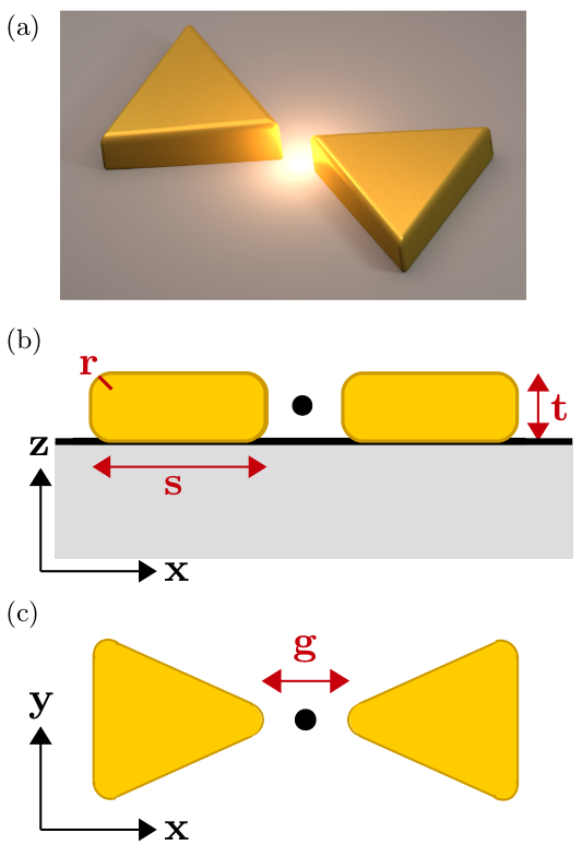
Dissipative modes, Purcell factors and directional beta factors in gold bowtie nanoantenna structures
Abstract
We present a detailed quasinormal mode analysis of gold bowtie nanoantennas, and highlight the unusual role of the substrate and the onset of multi-mode behaviour. In particular, we show and explain why the directional raditiave beta factor is completely dominated by emission into the substrate, and explain how the beta factors and quenching depend on the underlying mode properties. We also quantitatively explain the generalized Purcell factors and explore the role of gap size and substrate in detail. These rich modal features are essential to understand for future applications such as sensing, lasing, and quantum information processing, for example in the design of efficient single photon emitters.
I Introduction
The search for efficient quantum light sources and detectors is a rapidly expanding field in nanophotonics and plasmonics, offering new components in chip-based quantum electrodynamics (QED), with applications in quantum sensing and lasing. Part of the goals in achieving such devices, at the level of a single or a few quantum emitters, is to carefully engineer the light-matter interactions at the locations of the quantum emitters (e.g., a quantum dot, defect, or dye-sensitized molecule) to produce large enhancements in the electric field and thus the total spontaneous emission rate via the Purcell effect Purcell (1946).
It is well-known that plasmonic structures and antennas offer fundamentally different light-matter coupling behavior than dielectric or semiconductor photonics, e.g., they do not suffer from the usual spatial diffraction limits on the effective mode volume and they are intrinsically very fast (offering a broadband response). Consequently, plasmonic structures can enhance light-matter interactions by confining the optical fields to sub-nanoscale mode volumes, with orders of magnitude smaller mode volumes than the diffraction limit (e.g., even “picocavities” have been realized Benz et al. (2016))). Along with ultra-small mode volumes, metallic systems can also produce very high Purcell factors (PFs) – the enhancement of spontaneous emission relative to the homogeneous background – reported in the thousands (to hundreds of thousands) both theoretically Akselrod et al. (2014); Kamandar Dezfouli et al. (2017); Szenes et al. (2018) and experimentally Akselrod et al. (2014); Wei et al. (2016). However, the PF is not the only figure of merit (FOM) for such systems, since one goal in light emission and sensing is to be able to efficiently read-out the emitted photons “on demand”. Often this type of FOM is known as either the quantum efficiency or the radiative -factor (namely the probability that a single photon emitted will be detected in the far field), the latter of which will be used in this paper. These metrics are also essential to develop quantum FOMs for plasmon-based single photon sources Femius Koenderink (2017); Hughes et al. (2019).
Although plasmonic resonators offer high-PF interactions over a large broadband frequency range, which helps with the coupling to quantum emitters such as quantum dots and dye molecules Lyamkina et al. (2016); Chikkaraddy et al. (2016); Luo and Zhao (2019), the lossy nature of the metals creates a particularly difficult challenge for the -factor, as most of the photons can be lost to Ohmic heating or quenching Khurgin (2015); Axelrod et al. (2017). Yet, high beta factors are required to enable on-demand quantum light sources (and to help detection and sensitive Raman experiments), and it is important to understand their properties in a detailed an intuitive way.
Configurations of metallic nano-structures range from flat slab interfaces Zia et al. (2004) to single or ensembles of nanoparticles Fan et al. (2010) to slot waveguides Guo et al. (2008) to more complex geometries Winkler et al. (2017); Kamandar Dezfouli et al. (2017); Baranov et al. (2018), supporting many tunable resonances Seied Ali Tali and Zhou (2019) that are highly sensitive to geometry, size, and environment (e.g., background index of refraction or presence of other molecules). These resonator structures support lossy cavity modes with outgoing boundary conditions (which can be simulated numerically with perfectly matched layers, PMLs) for which the electric field propagates outward to infinity following the Silver-Müller radiation condition Kristensen et al. (2015) (i.e., outgoing/scattered waves must be spherical in the limit of , in the form ). However, since the frequency of the resonance is inherently complex, the spatial mode diverges in space and renders the usual Hermitian normalization conditions invalid since the surface integral of the electric field also diverges at infinity. Thus, the usual normal mode theory cannot be applied to lossy systems. One way to overcome this problem, is to use quasinormal mode (QNM) theory, which allows a rigorous definition of the effective mode volume, while working directly with the QNM complex eigenfrequency and thus loss. The properties of QNMs have been shown to accurately describe a plethora light-matter interactions of cavity systems Kristensen et al. (2012); Bai et al. (2013); Kristensen and Hughes (2014); Kamandar Dezfouli et al. (2017); Axelrod et al. (2017); Dezfouli et al. (2017); Alpeggiani et al. (2017); Lalanne et al. (2018); more importantly, the QNMs allows one to meaningfully talk about cavity FOMs in terms of the underlying mode theory, including coupled modes Vial and Hao (2016); Kristensen et al. (2017).
To achieve small mode volume and high electric field “hotspots,” dimer nanoantenna structures (two metal nanoparticles) are often employed with small gap sizes and various geometrical designs, including but not limited to nanorods Ge and Hughes (2014); Shcherbakov et al. (2015), cubes Wu et al. (2016); Hu et al. (2019), disks Alpeggiani et al. (2016), and nanospheres/shells Liaw et al. (2009). Bowties designs in particular are well exploited Fromm et al. (2004); Kinkhabwala et al. (2009); Suh et al. (2012); Schraml et al. (2014); Chou Chau et al. (2016); Kaniber et al. (2016); Lyamkina et al. (2016); Yan et al. (2018), though their basic cavity mode structure are not well understood. Thus there is an important need to better understand the optical properties of such structures from a cavity mode perspective, especially their radiative emission properties.
In this paper, we calculate and study the underlying QNM properties and directional beta factors for a gold bowtie dimer cavities, shown schematically in Fig. 1. These bowtie geometries are particularly interesting because of their pointed geometry at the gap, which produces a “lightening-rod effect” Liao and Wokaun (1982); Gramotnev et al. (2012), higher sensitivity to changes in geometry (i.e., gap, angle of tip, size, etc.) Fischer and Martin (2008) and polarization, and smaller non-radiative power losses Rogobete et al. (2007).
The rest of the paper is organised as follows: in Sec. II, a brief introduction to QNM theory is provided with all relevant equations used for this study. These modes are computed using COMSOL Multiphysics and an inverse Green function approach in complex frequency space Bai et al. (2013). The spatially dependent PFs are obtained analytically and also checked in terms of full dipole simulations, showing excellent agreement. Section III contains the main results which includes a detailed study of the effect of gap size, dipole position, multi-mode coupling, and substrate index of refraction. The main FOMs we present are the PF and -factor, where the mode volume, quality factor, and directionality of the -factor are also examined for the first four modes of the dimer systems, over a wide bandwidth. The main results show a splitting of the second-order mode from the inclusion of a substrate, as well as a red-shift of all four modes as the index of refraction of the substrate increasesFischer and Martin (2008); Kaniber et al. (2016). Most notably, a clear directionality to the -factor follows an unexpected trend which shows that most of the electromagnetic energy is “pulled” into the substrate, rather than reflected upward into the upper hemisphere half-space, as the substrate index increases. These results are then summarized and discussed by comparing the different modes and features in each design. Lastly, in Sec. IV, we present our conclusions.
II Theory
Quasinormal modes in optics are mode solutions of cavity structures with open-boundary cavities and are direct solutions to the vector Helmholtz equation in the complex frequency domain. Assuming non-magnetic media, the eigenvalue equation for the electric-field QNM is
| (1) |
where are the QNMs, are the complex eigenfrequencies, is the material permittivity (in general, complex), and is the mode number. For the gold dimer, the Drude model of metals is used to describe the permittivity, , where and are the plasma and collision frequencies; for gold, we use 1.26 rad/s (8.2935 eV) and 0.00141 rad/s (0.0093 eV), respectively. The photonic Green function, which is the electric field response to a single dipole emitter can be written in terms of a superposition of all QNMs over all pairs of space points, and Lee et al. (1999); Kristensen et al. (2017),
| (2) |
where is a complex and frequency dependent coupling constant, while the QNMs only depend on spatial position. The above expansion is accurate for spatial location within and near the resonator. In general, QNMs in dispersive media may be inherently non-orthogonal to one another Perrin (2016), but in this work, the coupling of two or more modes are performed under the assumption that the modes can be treated as orthogonal (i.e., non-diagonal elements of the coupling matrix are negligible) Bai et al. (2013); Kamandar Dezfouli et al. (2017). We also check this numerically by comparing with full dipole simulations with no approximations.
The normalization condition for such modes has been the subject of much interest Leung et al. (1994); Sauvan et al. (2013); Ge and Hughes (2014), since the usual normalization used for normal modes (formally, with real eigenfrequencies) is no longer valid. A simple way to obtain normalized modes is to exploit the solution of a scattering problem from a dipole (at ) in complex frequency space, which yield the mode in normalized form from the Green function solution Bai et al. (2013),
| (3) |
where is the dipole moment (related to the dipole current density, ), and the electric field of the mode is defined by the Green function and the dipole, , where the position of the dipole is . Note that in this equation is the frequency for which the electric field is obtained which is very close to the pole frequency; generally, we use .
In this formulation, the electric field as all spatial points in the simulation volume is obtained using a dipole current source; we use COMSOL Multiphysics (RF module), a commercially available frequency dependent solver for Maxwell’s equations COMSOL Inc. . There are several ways for which the pole of the modes can be obtained numerically. In this work, the pole is found by iterating through complex frequencies using a Padé approximation Bai et al. (2013), starting with an initial guess of the pole. For well-conditioned setups in which the mesh and PML settings have been carefully chosen for numerical stability (i.e., so that they do not produce fictitious solutions), and no more than 7-8 iterations are generally needed to converge to the pole frequency of any given mode. This frequency dependent method is not the only way of accurately obtaining the QNM complex poles, and there are also examples that use finite-difference time-domain algorithms (FDTD) Ge and Hughes (2014); Kamandar Dezfouli and Hughes (2018), and other finite-element solvers Lalanne et al. (2019).
The complex mode volume, (a “generalized” mode volume Kristensen et al. (2012)), as well as the quality factor, , are two key FOM for photonic cavities, where . Historally, in cavity physics, the mode volume is usually discussed in the context of normal modes. However, due to the inherent losses built into the QNM, the mode volume is expressed as a complex quantity, defined by:
| (4) |
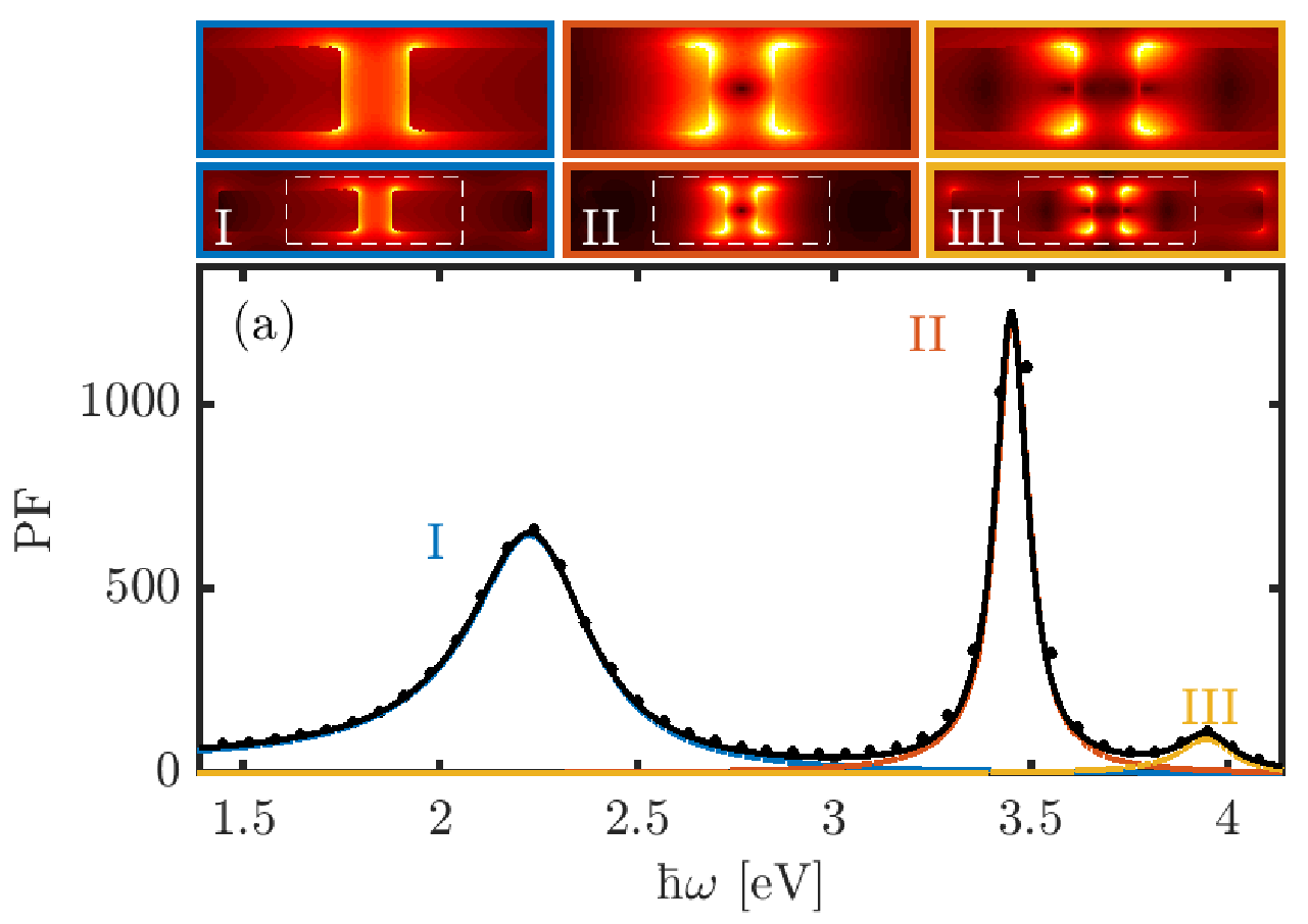
where the effective mode volume (e.g., for use in Purcell’s formula) is defined , and it is also a spatially dependent quantity; and is the background dielectric constant where the dipole is embedded (i.e., or as shown in Fig. 2).
The generalized Purcell factor is given by the ratio of the spontaneous emission rate with the resonator structure relative to the homogeneous medium Kristensen and Hughes (2014):
| (5) | ||||
where is the dipole direction.
It is important to also check the validity of a single or few mode QNM model. To do this, we can also obtain the numerical full-dipofrom a dipole at position , can be numerically obtained by obtaining the surface-integrated Poynting vector, from
| (6) |
where is the Poynting vector along the surface of a small sphere centred around the finite-size dipole ( 1-nm radius) at (shown in green in Fig. 2).
Using a similar approach, we can also obtain the numerical beta factor,
| (7) |
where is the Poynting vector along the surface over the spherical boundary between the system and the first PML, and is the unit vector normal to the integration surface; this allows us to capture the power in and out of the system to obtain meaningful and quantities. For a lossless dielectric system, then the beta factor is unity. Thus it had the interpretation of the probability that a single emitted photon will be emitted radiatively from the entire resonator system.
For the directional dependence of the emission, we adopt a convention for the -factor which splits into two quantities: the normalized radiated power in the + direction and - direction, which are shown in blue and red, respectively, in Fig. 2. These quantities are defined as:
| (8) |
and,
| (9) |
respectively, where () is the surface of the top(bottom) hemisphere of the PML boundary.
III Results
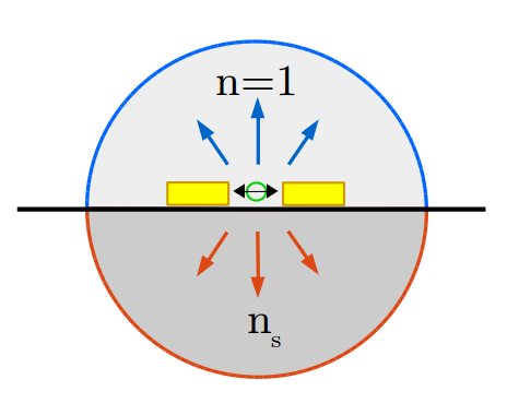
For our numerical calculations, the gold bowtie dimers are chosen to follow typical experimental dimensions reported in the literatureLyamkina et al. (2016); Schraml et al. (2016); Kaniber et al. (2016), including edges and vertices that are rounded. It is important to note that sharp features in metals are also notoriously difficult to model in any finite-mesh solving software, with the potential to create spurious hot-spots in the electric field (numerical artifacts). Thus, all edges and vertices are rounded with a curvature of =3 nm. The other dimensions, labelled in Fig. 1, are set to =90 nm and =35 nm, and the triangles are equilateral. The gap, , is defined as the gap between the un-rounded vertices, so for the geometry of equilateral triangles, the true gap size is larger by 2, such that (i.e. for a gap of 15 nm, the true gap is 21 nm). For clarity, only the true gap will be referred to here.
III.1 No substrate dimers (=1)
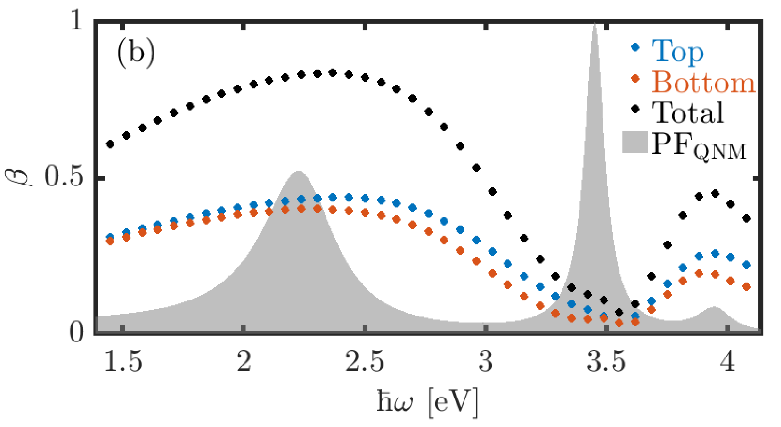
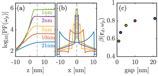
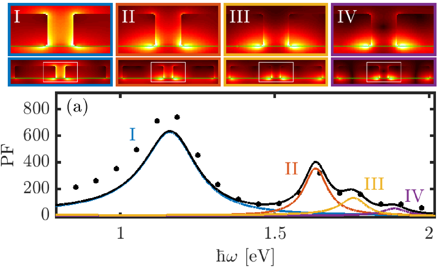
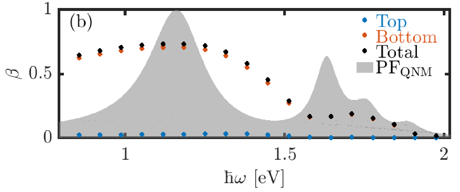
First, the PF and -factor are examined for the simplest case of no substrate (=1) with a dimer gap of 21 nm, shown in Fig. 3. Here, markers indicate the full-dipole values obtained using Eqs. (6)-(9), and the QNM calculations for the first three modes (I-III) are given by solid colored lines [(5)]. To better see the correlation with PF and beta factor, the QNM-calculated PF is shown in arbitrary units for the beta simulation. There are a few notable features on this graph, starting with the excellent agreement between the full-dipole PF and the 3-mode QNM calculation over the entire frequency range shown (spanning around 3 eV). The PF of mode I and II exceed 600 and 1200, respectively. Interestingly, the -factor exceeds 80% and 40% for mode I and III but is greatly suppressed below 15% for mode II, which means that although mode II has the largest PF of the three modes, it is mainly non-propagating to the far-field. Lastly, there is some asymmetry between the upper and lower hemispheres, even though there is no substrate to break the symmetry, but it is expected that the upper hemisphere will have a slightly larger -factor due to the off-center geometry of the COMSOL setup (see Fig. 2) and location of the dipole. The largest absolute difference is approximately 5%.
We also note that the nonraditive modal contribution to the decay can also be obtained directly from the QNM technique, through: Anger et al. (2006)
| (10) |
where is the induced current density within the metal dimer. In this way, where is the total decay rate (radiative + non-radiative, or PF). Note that the Green functions can be obtained directly from Eq. (2). However, this quantity can be difficult to obtain numerically (requiring a complex 3D integration per frequency), and it is easier to just obtain this directly from the dipole simulation. Nevertheless, this expression is useful to explain the general quenching of mode III, since the non-radiative decay is directly proportional to within the metal.
Figure. 4 shows the peak PF of mode I (see Fig. 3) as a function of gap size and position and position, as well as the -factor evaluated at the dipole location (=5 nm and 0 nm). As expected, the PF increases as the dipole location gets closer to the metal boundaries at the cost of the -factor decreasing. The small oscilaltions in the PF, particularly seen for the gap of 1 and 2 nm, are numerical artifacts/fluctuations arising from difficulty interpolating the spatial mesh at such a small scales.
III.2 Dimers on a low-index substrate
In the majority of experimental dimer setups, the dimers are placed on top of a substrate with an index of refraction greater than 1, usually glass or a high-index semiconductor such as GaAs Chen et al. (2012); Schraml et al. (2014); Lyamkina et al. (2016); Kaniber et al. (2016). To study the effects of adding a high-index substrate, the QNMs are examined starting at =1.2, increasing to 1.5 (glass), 2.0, and then finally to 3.5 (e.g., GaAs).
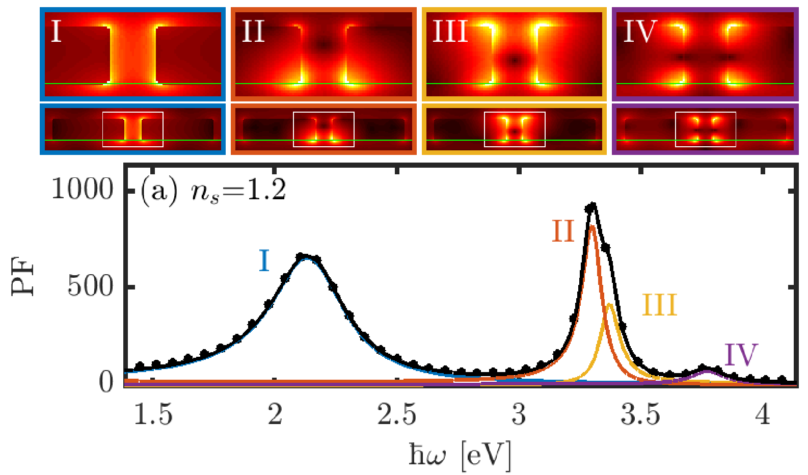
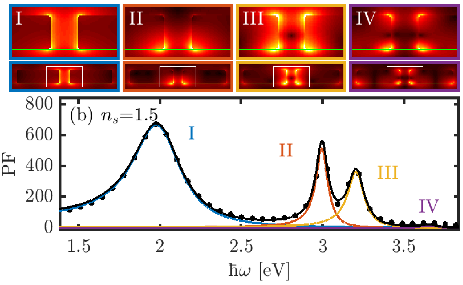
Figure 5 shows the same simulations as in Fig. 3 except we now use = 1.2 and 1.5. Immediately upon breaking the spatial symmetry (in the vertical direction), as seen by the =1.2 results, mode II splits into two distinct modes (now labelled by II and III) but mode I and III (now labelled IV) remain unchanged apart from minor perturbations from symmetry breaking. This splitting is spectrally more dramatic as the index of the substrate increases, and one can see that this also prompts mode I to have the largest PF of the four modes. Also, between mode II and III, only one of them (II) is suppressed in while the other (III) spikes back up, confirming further that these are two distinctly different modes.
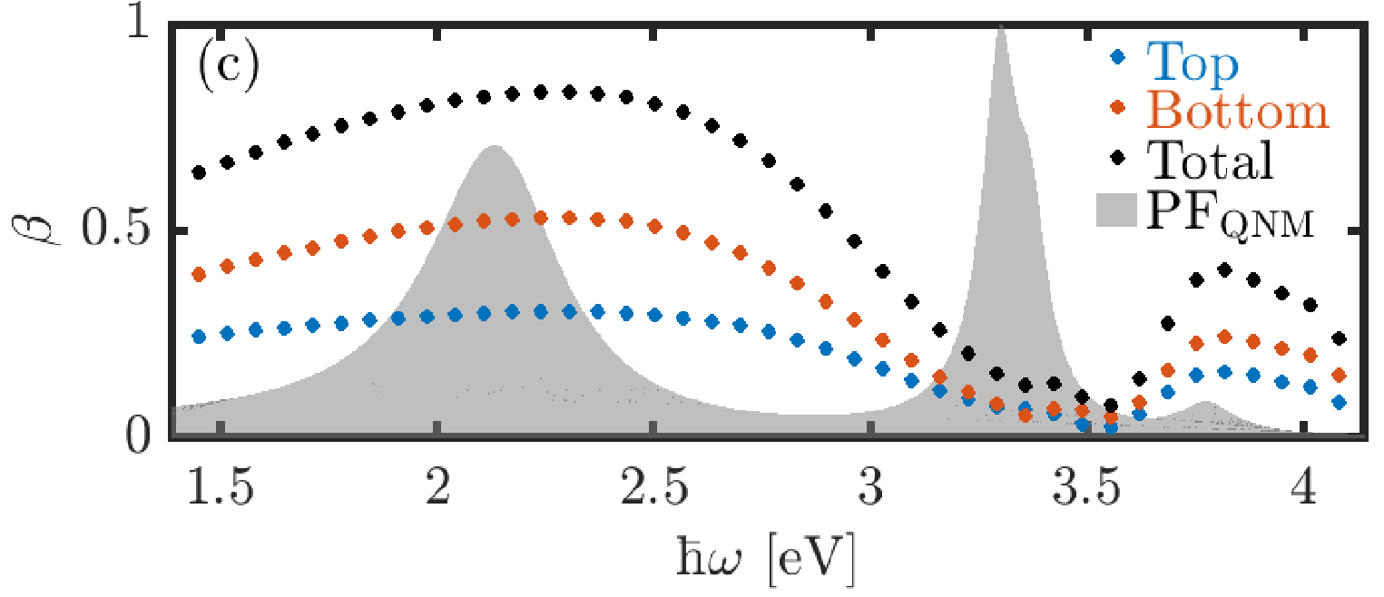
It is also important to note the effect of the substrate on the symmetry of the direction -factor; against intuition with a dipole above a slab of dielectric, which is that the power flow from a dipole should be directed mainly into its own hemisphere in the presence of a substrate (even a semiconductor which is a very poor mirror), it is seen that the opposite trend is present. Namely, as the index of the substrate increases, the power flow into the lower (substrate) hemisphere becomes much larger relative to the upper hemisphere emission. This can be explained by examining the spatial mode profiles of the QNMs. There, the electric field is seemingly “pulled” downward into the substrate, so if the highest points of the field lives below the surface of the substrate, then it is in-fact directed downward. This result is important, as typical experiments would measurement the -factor from the power flow in the reflected (upper) direction, and thus there is a lot of power flow that is potentially missed by not considering the power flow in the downward direction.
III.3 Dimers on a high-index substrate
| Mode | I | II | III | |
|---|---|---|---|---|
| 2.23908 | 3.45248 | 3.95269 | ||
| - 0.18611 | - 0.05084 | - 0.08333 | ||
| 6.0 | 34.0 | 23.7 | ||
| 0.00071 | 0.00209 | 0.01902 | ||
| 646.6 | 1238.3 | 94.8 | ||
| 0.43 | 0.06 | 0.26 | ||
| 0.40 | 0.05 | 0.19 | ||
| Mode | I | II | III | IV |
| 1.16635 | 1.63159 | 1.75944 | 1.88932 | |
| - 0.10463 | - 0.04555 | - 0.05040 | - 0.04623 | |
| 5.6 | 17.9 | 17.5 | 20.4 | |
| 0.00067 | 0.00381 | 0.00988 | 0.02859 | |
| 628.7 | 356.4 | 133.8 | 54.5 | |
| 0.03 | 0.002 | 0.004 | 0.002 | |
| 0.71 | 0.17 | 0.17 | 0.04 | |
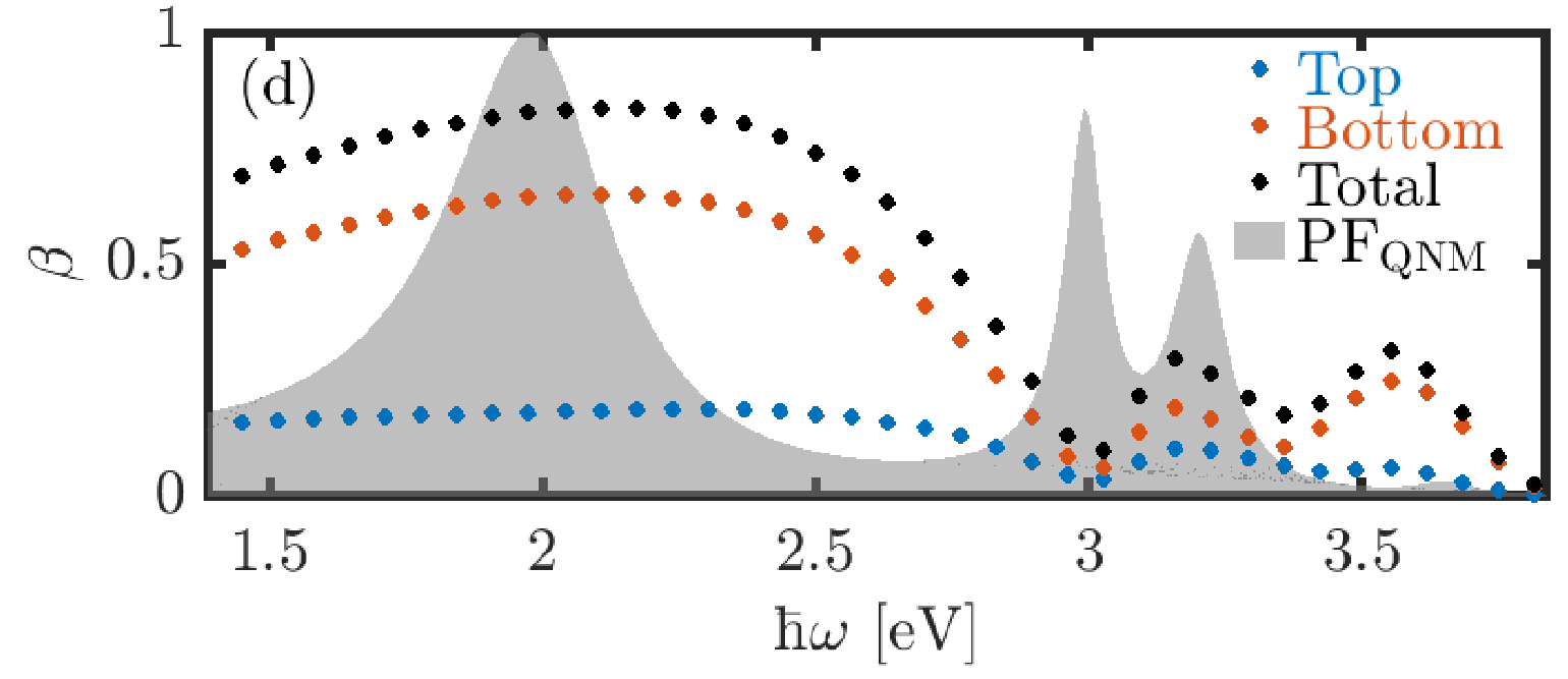
Next, the same analysis is applied to the larger index of =3.5, which is similar to GaAs in the optical regime of the spectrum, as seen in Fig. 6. As expected from the low-index data, there is a significant red-shift of the four modes of interest, and the -factor is now almost completely dominated by emission into the lower hemisphere. Also shown in Fig. 6, are the mode profiles of the and components of the electric field for each of the four modes at their pole frequencies, showing the different symmetries of the different modes. However, we note that the QNM fit to the full-dipole calculations is not as good as in the other data sets, with a larger discrepancy for lower frequencies. This suggests that the quasi-static contributions of the Green function Ge et al. (2014) could be playing a a more important role here, which we discuss in more detail in the next section. Alternatively, there may be some background small modes. Nevetheless, we still obtain a very good QNM fit to all but the lowest mode.
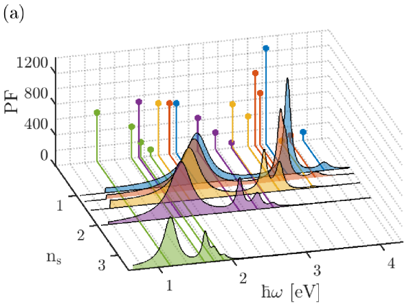
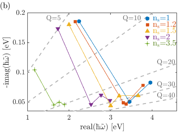
Figure 7 shows a summary of the QNM PFs as a function of the substrate index of refraction, highlighting the peak PFs for each mode at its pole frequency. This illustrates the red-shifting of all modes as well as the splitting of the original mode II into two distinct modes. In addition, Fig. 7 provides a summary of the QNM pole frequencies in complex frequency space. The dashed lines represent constant quality factors, and the lines connecting markers are simply used to guide the eye and group data points for each index of refraction (the modes are, indeed, discrete from each other).
Table 1 summarizes the PF, -factor (upper/lower), pole frequency, quality factor, and effective mode volume for all of the calculated modes for and . The upper -factor for the high-index substrate is approximately 2-5% of that in the lower hemisphere with the lower -factor reaching as high as 0.71 for mode I. Compared to no substrate, which has a peak -factor total of 0.83 split evenly between upper and lower hemispheres, the directional behaviour of is important to consider when measuring the quantity. The mode volumes, quality factors, and PFs for each case are similar in magnitude, however the higher index appears to result in over-all larger mode volumes as well as lower quality factors and lower PFs – especially for the special case of mode II from no substrate, which ‘splits’ into two lower Q modes (II and III) with substrate where the Q of these modes is approximately half that of the original single mode.
III.4 Discussion and Graphical Summary of Mode Contributions for Different Substrates
To compare briefly to other related works in the literature, a 2012 study by Chen et al.Chen et al. (2012) showed that for a single metal nanoparticle on a substrate, the role of the index of the substrate was counter to our results; namely, they calculated that the -factor increased substantially (from 20% to 60%) by increasing from 1.0 to 3.5. In this study, the gap mode is determined by the gap between the metal nanoparticle and the dielectric substrate, rather than the metallic dimer gap in our study. To the best of our knowledge, the effect of the substrate on the -factor (also referred to as quantum efficiency), and more importantly, the directionality of the -factor has not been demonstrated theoretically or experimentally for metallic dimer structures; however, a recent paper by Zhou et. al.Zhang (2019) has demonstrated for a single nanorod (dielectric or metallic), the -factor is directed predominantly into the higher-index medium if placed on a substrate, supporting our results.
In an attempt to increase the upward directionality of the -factor, a 5 nm spacer layer with was included between the GaAs substrate and gold dimer. We found that the total -factor is increased over the whole broadband spectrum, most notably increasing from 20% for modes II-IV to over 50%. The directionality is also slightly increased in the upward direction, but only to less than 10% of the total. Also, the QNMs are substantially blue-shifted due to the effect of the effective-index of the glass and GaAs heterostructure.
Another potential way to enhance the upward -factor is to include a gold reflector below the substrate (e.g., 100 nm below). We also carried out such calculations and the upper (lower) -factor for the first mode is approximately 16% (40%), whereas the original structure produced 3% (71%), resulting in a change in the ratio of upward-to-downward from to . However, that the total -factor decreases over the entire broadband spectrum (from 74% to 56% at mode I and from 6-20% to less than 3% over modes II-IV), and the PF remains approximately the same – note that the modal properties of the resonances were mainly unchanged from those in Fig. 6.
One could also attempt to increase the beta factor by using -enhancing hetero-structures and designs Lee et al. (2011); Zhang (2019); Wiecha et al. (2019) or microlenses Ee et al. (2007), but such designs are outside the scope of this paper, and they would be quite challenging to exploit over such a wide spectral range.
IV Conclusions
We have employed a QNM technique to study the main resonant modes and complex frequencies of a gold bowtie dimer with (without) a substrate. The effects of dimer gap size, dipole position, as well as substrate index of refraction were studied for the PF and -factor with a dipole oriented along the axis of the dimer. As expected, larger PFs were obtained for smaller gaps with losses to the total -factor; however, the total -factor, even for small gaps of 0.5-2 nm, remained above 50-60% which is quite remarkable for an un-optimized design. The -factor was further examined by splitting it into its upper and lower hemisphere contributions. Two unexpected observations were made for the inclusion of the substrate of =1.2: first, the second mode in the system ‘split’ into two distinctly different modes with different electric field profiles, and the poles of these two modes moved further from each other (in complex frequency space) as the index of the substrate increased. Second, the -factor un-intuitively became increasingly directed in the downward (into the substrate) direction as the index increased. This effect can be explained by examining the electric field profiles at the pole, noting how the electric field is ‘pulled’ into the substrate compared to the no-substrate case. These results are not currently discussed in the literature, and could have possibly important consequences for how the photons in such systems are collected for optimal -factor output. Further work includes modelling the structure for optimal properties in PF and -factor, including spacer layers, distributed Bragg mirror substrates, and geometrical factors in the bowtie design.
Acknowledgements.
This work was supported by the Natural Sciences and Engineering Research Council of Canada, the Canadian Foundation for Innovation and Queen’s University.References
- Purcell (1946) E. M. Purcell, “Spontaneous emission probabilities at radio frequencies,” Phys. Rev. 69, 681 (1946).
- Benz et al. (2016) Felix Benz, Mikolaj K. Schmidt, Alexander Dreismann, Rohit Chikkaraddy, Yao Zhang, Angela Demetriadou, Cloudy Carnegie, Hamid Ohadi, Bart de Nijs, Ruben Esteban, Javier Aizpurua, and Jeremy J. Baumberg, “Single-molecule optomechanics in “picocavities”,” Science 354, 726–729 (2016).
- Akselrod et al. (2014) Gleb M. Akselrod, Christos Argyropoulos, Thang B. Hoang, Cristian Ciracì, Chao Fang, Jiani Huang, David R. Smith, and Maiken H. Mikkelsen, “Probing the mechanisms of large Purcell enhancement in plasmonic nanoantennas,” Nature Photonics 8, 835–840 (2014).
- Kamandar Dezfouli et al. (2017) Mohsen Kamandar Dezfouli, Reuven Gordon, and Stephen Hughes, “Modal theory of modified spontaneous emission of a quantum emitter in a hybrid plasmonic photonic-crystal cavity system,” Physical Review A 95, 013846 (2017).
- Szenes et al. (2018) András Szenes, Balázs Bánhelyi, Tibor Csendes, Gábor Szabó, and Mária Csete, “Enhancing Diamond Fluorescence via Optimized Nanorod Dimer Configurations,” Plasmonics 13, 1977–1985 (2018).
- Wei et al. (2016) Wei Wei, Xin Yan, and Xia Zhang, “Ultrahigh Purcell factor in low-threshold nanolaser based on asymmetric hybrid plasmonic cavity,” Scientific Reports 6, 33063 (2016).
- Femius Koenderink (2017) A. Femius Koenderink, “Single-photon nanoantennas,” ACS Photonics 4, 710–722 (2017).
- Hughes et al. (2019) Stephen Hughes, Sebastian Franke, Chris Gustin, Mohsen Kamandar Dezfouli, Andreas Knorr, and Marten Richter, “Theory and limits of on-demand single-photon sources using plasmonic resonators: A quantized quasinormal mode approach,” ACS Photonics 6, 2168–2180 (2019).
- Lyamkina et al. (2016) A. A. Lyamkina, K. Schraml, A. Regler, M. Schalk, A. K. Bakarov, A. I. Toropov, S. P. Moshchenko, and Michael Kaniber, “Monolithically integrated single quantum dots coupled to bowtie nanoantennas,” Opt. Express 24, 28936–28944 (2016).
- Chikkaraddy et al. (2016) Rohit Chikkaraddy, Bart de Nijs, Felix Benz, Steven J. Barrow, Oren A. Scherman, Edina Rosta, Angela Demetriadou, Peter Fox, Ortwin Hess, and Jeremy J. Baumberg, “Single-molecule strong coupling at room temperature in plasmonic nanocavities,” Nature 535, 127–130 (2016).
- Luo and Zhao (2019) Yi Luo and Jing Zhao, “Plasmon-exciton interaction in colloidally fabricated metal nanoparticle-quantum emitter nanostructures,” Nano Research (2019), 10.1007/s12274-019-2390-z.
- Khurgin (2015) Jacob B. Khurgin, “How to deal with the loss in plasmonics and metamaterials,” Nature Nanotechnology 10, 2–6 (2015).
- Axelrod et al. (2017) Simon Axelrod, Mohsen Kamandar Dezfouli, Herman M. K. Wong, Amr S. Helmy, and Stephen Hughes, “Hyperbolic metamaterial nanoresonators make poor single-photon sources,” Physical Review B 95, 155424 (2017).
- Zia et al. (2004) Rashid Zia, Mark D. Selker, Peter B. Catrysse, and Mark L. Brongersma, “Geometries and materials for subwavelength surface plasmon modes,” JOSA A 21, 2442–2446 (2004).
- Fan et al. (2010) Jonathan A. Fan, Chihhui Wu, Kui Bao, Jiming Bao, Rizia Bardhan, Naomi J. Halas, Vinothan N. Manoharan, Peter Nordlander, Gennady Shvets, and Federico Capasso, “Self-Assembled Plasmonic Nanoparticle Clusters,” Science 328, 1135–1138 (2010).
- Guo et al. (2008) Hongcang Guo, Todd P. Meyrath, Thomas Zentgraf, Na Liu, Liwei Fu, Heinz Schweizer, and Harald Giessen, “Optical resonances of bowtie slot antennas and their geometry and material dependence,” Optics Express 16, 7756–7766 (2008).
- Winkler et al. (2017) Robert Winkler, Franz-Philipp Schmidt, Ulrich Haselmann, Jason D. Fowlkes, Brett B. Lewis, Gerald Kothleitner, Philip D. Rack, and Harald Plank, “Direct-Write 3d Nanoprinting of Plasmonic Structures,” ACS Applied Materials & Interfaces 9, 8233–8240 (2017).
- Baranov et al. (2018) Denis G. Baranov, Martin Wersäll, Jorge Cuadra, Tomasz J. Antosiewicz, and Timur Shegai, “Novel nanostructures and materials for strong light–matter interactions,” ACS Photonics 5, 24–42 (2018).
- Seied Ali Tali and Zhou (2019) Safiabadi Seied Ali Tali and Wei Zhou, “Multiresonant plasmonics with spatial mode overlap: overview and outlook,” Nanophotonics 8, 1199–1225 (2019).
- Kristensen et al. (2015) Philip Trøst Kristensen, Rong-Chun Ge, and Stephen Hughes, “Normalization of quasinormal modes in leaky optical cavities and plasmonic resonators,” Physical Review A 92, 053810 (2015).
- Kristensen et al. (2012) P. T. Kristensen, C. P. Van Vlack, and S. Hughes, “Generalized effective mode volume for leaky optical cavities,” Opt. Lett. 37, 1649 (2012).
- Bai et al. (2013) Q. Bai, M. Perrin, C. Sauvan, J.-P. Hugonin, and P. Lalanne, “Efficient and intuitive method for the analysis of light scattering by a resonant nanostructure,” Optics Express 21, 27371–27382 (2013).
- Kristensen and Hughes (2014) Philip Trøst Kristensen and Stephen Hughes, “Modes and Mode Volumes of Leaky Optical Cavities and Plasmonic Nanoresonators,” ACS Photonics 1, 2–10 (2014).
- Dezfouli et al. (2017) Mohsen Kamandar Dezfouli, Christos Tserkezis, N. Asger Mortensen, and Stephen Hughes, “Nonlocal quasinormal modes for arbitrarily shaped three-dimensional plasmonic resonators,” Optica 4, 1503–1509 (2017).
- Alpeggiani et al. (2017) Filippo Alpeggiani, Nikhil Parappurath, Ewold Verhagen, and L. Kuipers, “Quasinormal-mode expansion of the scattering matrix,” Phys. Rev. X 7, 021035 (2017).
- Lalanne et al. (2018) Philippe Lalanne, Wei Yan, Kevin Vynck, Christophe Sauvan, and Jean-Paul Hugonin, “Light Interaction with Photonic and Plasmonic Resonances,” Laser & Photonics Reviews 12, 1700113 (2018).
- Vial and Hao (2016) Benjamin Vial and Yang Hao, “A coupling model for quasi-normal modes of photonic resonators,” Journal of Optics 18, 115004 (2016).
- Kristensen et al. (2017) Philip Trost Kristensen, Jakob Rosenkrantz de Lasson, Mikkel Heuck, Niels Gregersen, and Jesper Mork, “On the theory of coupled modes in optical cavity-waveguide structures,” Journal of Lightwave Technology 35, 4247–4259 (2017).
- Ge and Hughes (2014) Rong-Chun Ge and S. Hughes, “Design of an efficient single photon source from a metallic nanorod dimer: a quasi-normal mode finite-difference time-domain approach,” Opt. Lett. 39, 4235 (2014).
- Shcherbakov et al. (2015) Maxim R. Shcherbakov, Anton T. Le, Natalia Dubrovina, Anatole Lupu, and Andrey A. Fedyanin, “Plasmon ruler with gold nanorod dimers: utilizing the second-order resonance,” Optics Letters 40, 1571–1574 (2015).
- Wu et al. (2016) Lin Wu, Shu Fen Tan, Michel Bosman, Joel K. W. Yang, Christian A. Nijhuis, and Ping Bai, “Charge transfer plasmon resonances across silver–molecule–silver junctions: estimating the terahertz conductance of molecules at near-infrared frequencies,” RSC Advances 6, 70884–70894 (2016).
- Hu et al. (2019) Huatian Hu, Shunping Zhang, and Hongxing Xu, “Closely packed metallic nanocuboid dimer allowing plasmomechanical strong coupling,” Physical Review A 99, 033815 (2019).
- Alpeggiani et al. (2016) F. Alpeggiani, S. D’Agostino, D. Sanvitto, and D. Gerace, “Visible quantum plasmonics from metallic nanodimers,” Scientific Reports 6, 34772 (2016).
- Liaw et al. (2009) Jiunn-Woei Liaw, Jeng-Hong Chen, Chi-San Chen, and Mao-Kuen Kuo, “Purcell effect of nanoshell dimer on single molecule’s fluorescence,” Optics Express 17, 13532 (2009).
- Fromm et al. (2004) David P. Fromm, Arvind Sundaramurthy, P. James Schuck, Gordon Kino, and W. E. Moerner, “Gap-Dependent Optical Coupling of Single “Bowtie” Nanoantennas Resonant in the Visible,” Nano Letters 4, 957–961 (2004).
- Kinkhabwala et al. (2009) Anika Kinkhabwala, Zongfu Yu, Shanhui Fan, Yuri Avlasevich, Klaus Müllen, and W. E. Moerner, “Large single-molecule fluorescence enhancements produced by a bowtie nanoantenna,” Nature Photonics 3, 654–657 (2009).
- Suh et al. (2012) Jae Yong Suh, Chul Hoon Kim, Wei Zhou, Mark D. Huntington, Dick T. Co, Michael R. Wasielewski, and Teri W. Odom, “Plasmonic Bowtie Nanolaser Arrays,” Nano Letters 12, 5769–5774 (2012).
- Schraml et al. (2014) K. Schraml, M. Spiegl, M. Kammerlocher, G. Bracher, J. Bartl, T. Campbell, J. J. Finley, and M. Kaniber, “Optical properties and interparticle coupling of plasmonic bowtie nanoantennas on a semiconducting substrate,” Physical Review B 90, 035435 (2014).
- Chou Chau et al. (2016) Yuan-Fong Chou Chau, Chung-Ting Chou Chao, Jhin-Yu Rao, Hai-Pang Chiang, Chee Ming Lim, Ren Chong Lim, and Nyuk Yoong Voo, “Tunable Optical Performances on a Periodic Array of Plasmonic Bowtie Nanoantennas with Hollow Cavities,” Nanoscale Research Letters 11, 411 (2016).
- Kaniber et al. (2016) M. Kaniber, K. Schraml, A. Regler, J. Bartl, G. Glashagen, F. Flassig, J. Wierzbowski, and J. J. Finley, “Surface plasmon resonance spectroscopy of single bowtie nano-antennas using a differential reflectivity method,” Scientific Reports 6, 23203 (2016).
- Yan et al. (2018) Wei Yan, Rémi Faggiani, and Philippe Lalanne, “Rigorous modal analysis of plasmonic nanoresonators,” Phys. Rev. B 97, 205422 (2018).
- Liao and Wokaun (1982) P. F. Liao and A. Wokaun, “Lightning rod effect in surface enhanced Raman scattering,” The Journal of Chemical Physics 76, 751–752 (1982).
- Gramotnev et al. (2012) Dmitri K. Gramotnev, Anders Pors, Morten Willatzen, and Sergey I. Bozhevolnyi, “Gap-plasmon nanoantennas and bowtie resonators,” Phys. Rev. B 85, 045434 (2012).
- Fischer and Martin (2008) Holger Fischer and Olivier J. F. Martin, “Engineering the optical response of plasmonic nanoantennas,” Optics Express 16, 9144 (2008).
- Rogobete et al. (2007) Lavinia Rogobete, Franziska Kaminski, Mario Agio, and Vahid Sandoghdar, “Design of plasmonic nanoantennae for enhancing spontaneous emission,” Optics Letters 32, 1623–1625 (2007).
- Lee et al. (1999) K. M. Lee, P. T. Leung, and K. M. Pang, “Dyadic formulation of morphology-dependent resonances. I. Completeness relation,” JOSA B 16, 1409–1417 (1999).
- Perrin (2016) Mathias Perrin, “Eigen-energy effects and non-orthogonality in the quasi-normal mode expansion of Maxwell equations,” Optics Express 24, 27137–27151 (2016).
- Leung et al. (1994) P. T. Leung, S. Y. Liu, and K. Young, “Completeness and time-independent perturbation of the quasinormal modes of an absorptive and leaky cavity,” Phys. Rev. A 49, 3982–3989 (1994).
- Sauvan et al. (2013) C. Sauvan, J. P. Hugonin, I. S. Maksymov, and P. Lalanne, “Theory of the spontaneous optical emission of nanosize photonic and plasmon resonators,” Phys. Rev. Lett. 110, 237401 (2013).
- (50) COMSOL Inc., “Comsol multiphysics v 5.3a,” www.comsol.com.
- Kamandar Dezfouli and Hughes (2018) Mohsen Kamandar Dezfouli and Stephen Hughes, “Regularized quasinormal modes for plasmonic resonators and open cavities,” Physical Review B 97, 115302 (2018).
- Lalanne et al. (2019) P. Lalanne, W. Yan, A. Gras, C. Sauvan, J.-P. Hugonin, M. Besbes, G. Demésy, M. D. Truong, B. Gralak, F. Zolla, A. Nicolet, F. Binkowski, L. Zschiedrich, S. Burger, J. Zimmerling, R. Remis, P. Urbach, H. T. Liu, and T. Weiss, “Quasinormal mode solvers for resonators with dispersive materials,” Journal of the Optical Society of America A 36, 686 (2019).
- Schraml et al. (2016) Konrad Schraml, Armin Regler, Johannes Bartl, Glenn Glashagen, Jakob Wierzbowski, Jonathan J. Finley, and Michael Kaniber, “Metamorphic plasmonic nanoantennas for self-enhanced nonlinear light generation,” Optica 3, 1453–1459 (2016).
- Anger et al. (2006) Pascal Anger, Palash Bharadwaj, and Lukas Novotny, “Enhancement and quenching of single-molecule fluorescence,” Phys. Rev. Lett. 96, 113002 (2006).
- Chen et al. (2012) Xue-Wen Chen, Mario Agio, and Vahid Sandoghdar, “Metallodielectric Hybrid Antennas for Ultrastrong Enhancement of Spontaneous Emission,” Physical Review Letters 108, 233001 (2012).
- Ge et al. (2014) Rong Chun Ge, Philip Trøst Kristensen, Jeff F. Young, and Stephen Hughes, “Quasinormal mode approach to modelling light-emission and propagation in nanoplasmonics,” New Journal of Physics 16, 113048 (2014).
- Zhang (2019) J.; Deng Z.-L.; Hu D.; Qin F.; Li X. Zhang, T.; Xu, “Unidirectional enhanced dipolar emission with an individual dielectric nanoantenna,” Nanomaterials 9, 629 (2019).
- Lee et al. (2011) K. G. Lee, X. W. Chen, H. Eghlidi, P. Kukura, R. Lettow, A. Renn, V. Sandoghdar, and S. Götzinger, “A planar dielectric antenna for directional single-photon emission and near-unity collection efficiency,” Nature Photonics 5, 166–169 (2011).
- Wiecha et al. (2019) Peter R. Wiecha, Clément Majorel, Christian Girard, Aurélien Cuche, Vincent Paillard, Otto L. Muskens, and Arnaud Arbouet, “Design of plasmonic directional antennas via evolutionary optimization,” Opt. Express 27, 29069–29081 (2019).
- Ee et al. (2007) Yik-Khoon Ee, Ronald A. Arif, Nelson Tansu, Pisist Kumnorkaew, and James F. Gilchrist, “Enhancement of light extraction efficiency of ingan quantum wells light emitting diodes using sio2/polystyrene microlens arrays,” Applied Physics Letters 91, 221107 (2007).