Scalable and Accurate Modeling of
the Millimeter Wave Channel
Abstract
Communication at millimeter wave (mmWave) frequencies is one of the main novelties introduced in the 5th generation (5G) of cellular networks. The opportunities and challenges associated with such high frequencies have stimulated a number of studies that rely on simulation for the evaluation of the proposed solutions. The accuracy of simulations largely depends on that of the channel model, but popular channel models for mmWaves, such as the Spatial Channel Models (SCMs), have high computational complexity and limit the scalability of the scenarios. This paper profiles the implementation of a widely-used SCM model for mmWave frequencies, and proposes a simplified version of the 3GPP SCM that reduces the computation time by up to 12.5 times while providing essentially the same distributions of several metrics, such as the Signal-to-Interference-plus-Noise Ratio (SINR) in large scale scenarios. We also give insights on the use cases in which using a simplified model can still yield valid results.
Index Terms:
5G, millimeter wave, channel model, 3GPPI Introduction
The 5G of cellular networks is the first to adopt frequencies above 6 GHz to provide access connectivity in mobile scenarios, thanks to the support of carrier frequencies up to 52.6 GHz in 3GPP NR [1], i.e., in the millimeter wave (mmWave) bands. This portion of the spectrum makes it possible to exploit large chunks of untapped bandwidth, enabling multi-gigabit-per-second data rates to the end-users of 5G networks. Additionally, at mmWaves it is possible to pack a large number of antenna elements in a small form factor, and this allows device manufacturers to embed large antenna arrays also in a smartphone or VR headset [2]. The usage of such high frequencies, however, introduces a set of challenges related to the harsh propagation environment, i.e., the high isotropic pathloss and the sensitivity to blockage [3]. In particular, the pathloss is proportional to the square of the carrier frequency and is significantly higher at mmWaves than in the sub-6 GHz band, limiting the coverage area of base stations operating in this band. Additionally, common materials (e.g., bricks and mortar) or the human body block the propagation of millimeter waves, and, consequently, the sudden appearance of an obstacle between the transmitter and the receiver can disrupt the communication or cause wide variations of the available capacity [2].
The peculiarities of the propagation environment at mmWaves have called for the introduction of novel solutions that span multiple layers of the protocol stack, from physical (e.g., with beamforming) to transport and application layers (to make the most out of the massive but erratic capacity available at mmWaves). In recent years, the research activities on mmWaves have addressed a number of these issues, for example by introducing the support of directional communications [4], ultra-dense networks [5] and efficient mobility management strategies [6].
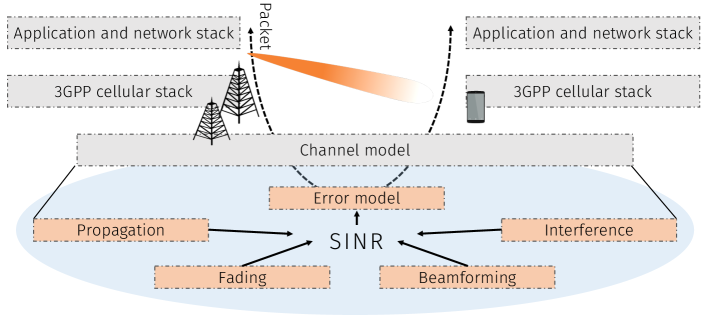
An important role in this research has been played by simulations. Indeed, given the early stage of the technological development at mmWaves, there is limited availability of open testbeds and/or real devices and commercial deployments to perform real-world and large-scale experiments. On the other hand, several open-source or commercial tools have been recently developed to perform link- and system-level simulations [7, 8, 9, 10]. Simulators, however, need to accurately model the mmWave channel, to precisely reproduce the effects that the propagation characteristics in these frequency bands introduce throughout the whole protocol stack. Fig. 1 shows the typical structure of a system-level simulator for mmWave networks: the basic unit is, in general, a packet, whose successful reception at the end device depends on an SINR value and an error model that maps it to a packet error rate. Therefore, a reliable estimation of the SINR, which depends on an accurate channel model, is fundamental in the overall performance evaluation.
However, modeling the mmWave channel is one of the most computationally intensive components of a simulation, given that it generally represents large antenna arrays and behaviors in multiple dimensions (i.e., space, time and frequency) [11]. SCMs, which are popular stochastic models for mmWave frequencies, require the generation of a channel matrix with as many elements as the product of the numbers of transmit and receive antenna elements [8, 12]. Ray tracers involve the computation of tens to hundreds of multipath components [13]. Some studies are based on simpler channel models, with an abstraction of the beamforming gain and Nakagami or Rayleigh fading [14]. However, as we highlight in our previous work [15], there exist accuracy and complexity tradeoffs when switching from an SCM to one of these simpler models.
In this paper, we investigate whether it is possible to simplify the structure of the widely used 3GPP SCM [12] without compromising the accuracy with respect to the original model, used as a baseline. First, we profile the computational complexity of the model and show that the computations with complex values related to the generation of steering vectors are the main factor that affects the time to generate an instance of the SCM channel. We then proceed to simplify these calculations by removing clusters and subpaths (i.e., spatial components of the channel) and comparing the performance of the baseline and simplified models. We show that some metrics (e.g., the distribution of the SINR in a typical 3GPP scenario [12]) are not (or only marginally) affected by this simplification, while the channel generation time reduces by up to 12.5 times. We also highlight the limitations that such a simplification introduces, and give insights on when it may be legitimate to use the simplified version of the model.
The remainder of the paper is organized as follows. In Section II we review the main characteristics of mmWave channel models, with a focus on SCMs. We then profile the complexity of these models in Section III. Section IV reports our method and the results of the simplification. Finally, we provide suggestions for future work in Section V.
II MmWave Channel Models
The accurate modeling of propagation and fading in the mmWave bands has been a topic at the forefront of research in recent years, with multiple measurements and modeling campaigns, such as those described in [16, 17]. The review of mmWave channel models in [18] identifies some basic characteristics of the mmWave propagation, i.e., a higher propagation and penetration loss than at sub-6 GHz, the sparsity in the angular domain, the impact of blockage and the clear distinction between Line-of-Sight (LoS) and Non-Line-of-Sight (NLoS) states, and the reduced impact of small scale fading.
Channel models for mmWaves can be grouped into three broad classes. Quasi-deterministic models [19] are extremely accurate in specific scenarios, but need a detailed model of the environment, and are computationally very demanding. On the other side, models used in analytical studies are based on Nakagami or Rayleigh fading and are usually coupled with a basic sectorized beamforming model [14]. These models simplify the computation of the channel, but are not geometrically related to the scenario, and cannot capture, for example, the spatial dimension of a mmWave channel.
A compromise is usually found using SCMs, a class of stochastic models that extend the WINNER and WINNER-II models [20], can model interactions with beamforming vectors, and have been chosen by the 3GPP for system-level evaluations of 5G networks [21]. In this paper, we focus on the simplification of the 3GPP model for frequencies in the 0.5 to 100 GHz range [12].
An SCM is given by a propagation loss and a fading model. The first characterizes the LoS state of the link (probabilistically or with a precise description of the environment) and the average channel gain, with different equations for the LoS and NLoS conditions [22].
To model fading, the SCM represents the channel with a matrix , with rows and columns, that correspond to the transmit/receive antenna elements. The entry of the matrix is given by the combination of clusters, which model different angular components of the channel between the two transceivers. The power of each cluster is modeled through an exponential power delay profile, which depends on the delay with which each of the different clusters arrives at the receiver. Therefore, the LoS path (if present) is the strongest cluster, associated to the minimum delay, followed by several reflections. Additionally, each cluster can be modeled by the superposition of subpaths111The 3GPP specifications refer to subpaths as rays., which are distributed with certain statistics around the Angle of Arrival (AoA) and Angle of Departure (AoD) of the cluster.
A single realization of the matrix depends on the combination of large scale and fast fading parameters. The first have an impact on the power delay profile, the angular distribution, the relative strength of the LoS component with respect to the NLoS reflections, and the shadowing. Large scale parameters generally depend on the scenario that is being modeled. Fast fading, instead, models small variations in the channel, e.g., the Doppler spread introduced by the user mobility. The actual parameters may vary in different SCMs, and are generally expressed through random distributions that fit data collected in measurement campaigns.
SCMs are popular in the mmWave domain because they have been developed to support beamforming and antenna arrays. The beamforming gain can indeed be obtained by combining the beamforming vectors for the transmitter and the receiver with the channel matrix [23]. However, as we will discuss in the next section, the associated computation is one of the most time-consuming parts of the channel generation.
III Profiling of the 3GPP mmWave Channel Model
In order to proceed with the simplification of the model, an initial analysis is necessary to understand which are the most computationally demanding steps in the channel generation process. To remove the dependency on the implementation as much as possible and decouple the model complexity from the implementation inefficiencies, a 3GPP-compliant [12, 21] network simulator was designed and optimized. With this tool, we verified experimentally that the channel matrix generation takes up to of the simulation time (the remaining overhead is given by the scenario definition, user mobility, beamforming vector computations, statistical computation, among others). Although the performance is implementation-dependent, analyzing how the computation of the different parts contributes to the overall simulation time allows drawing general conclusions.
When antenna arrays are considered, the channel model can no longer be expressed through a time-varying scalar impulse response. Rather, as discussed in Section II, the channel response is enclosed in a matrix that associates each of the elements of the transmitting array, to each of the elements of the receiving array. As channel models generate a number of rays coming from different directions, a way to translate such directionality into the definition of the channel matrix is needed. Considering a narrow-band signal and a small-aperture antenna, the incoming signal seen from the point of view of any given antenna element will be a phase-shifted copy of the original signal. Steering vectors are used to represent this phase shift over all array elements and are thus composed of complex phase shifts. Please note that this concept is valid for clusters incoming (or departing) from any direction and for arbitrary arrays. As mmWave use cases are expected to be mainly focused on arrays with tens or hundreds of antennas, the code has been optimized for such scenarios, partially degrading the performance when a small number of antennas (e.g., one at both transmitter and receiver) is used.
Our profiling highlights that the computations related to steering vectors and their combination are the most time-consuming part of the generation of an instance of the matrix representing the 3GPP channel, as reported in the Computations entry in Fig. 2. For a channel with a single element (i.e., ), the computation takes 79.42% of the time. This percentage increases up to 90.38% for the largest antenna array configuration we consider (i.e., ).222Notice that the dependence between the number of antenna elements and the Computations entries is not linear, as MATLAB introduces optimizations for large matrices. The generation of random variables, such as the cluster powers, the delays, the sub-paths’ angles, the phase shifts, and the AoA/AoD coupling, is instead negligible, particularly when large arrays are considered (0.27% for the configuration). On the contrary, the code overhead, composed of sub-routine calls and all other operations, is significant and does not considerably depend on the array size.
As the Computations entry is related to the generation and combination of the steering vectors, it is proportional to the number of clusters and subpaths that are generated and combined: the richer the channel, the slower this computation. For example, as reported in Fig. 2, a channel with a single entry would take up to ms to perform the computations for a total of ms, while for the largest antenna configuration, yielding the largest channel matrix, computations take ms for a total of ms.
IV Channel Simplification
As shown by the analysis in Section II, reducing the number of clusters and subpaths can be beneficial in terms of simulation time. Nevertheless, changes in the channel model may affect or even compromise its reliability, depending on the application. In this section, we analyze the effects of the simplification on the network statistics obtained from the network simulator described in Section III. The models with the original number of clusters and sub-paths were considered as baselines with which to compare the effects of the simulations, i.e., we do not provide in this paper a direct comparison with ground truth measurements. Thanks to the flexibility of our simulator, it was possible to perform the tests on different configurations of the 3GPP channel model while keeping the same settings for the cellular scenario. For this study, a 3GPP-compliant Urban Macro (UMa) downlink scenario is considered [12]. Similar results can also be obtained for other scenarios.
The 3GPP channel model differentiates among three states of the channel, namely LoS, NLoS, and Outdoor-to-Indoor (O2I). Different channel states correspond to a different number of clusters, whereas the number of sub-paths per cluster is kept fixed for all propagation conditions. As per [12], clusters are present in LoS, in NLoS, and in O2I channel conditions, in short .
We followed two complementary simplification strategies: on one hand, reducing the number of clusters, and on the other hand, reducing the number of sub-paths per cluster. Indeed, it was possible to vary the latter from to , corresponding to a cluster with only the main path and no sub-paths. On the contrary, in [12], the azimuth and elevation angle spreads are specified only for some specific cluster configurations, and cannot be trivially interpolated to extract the parameters for the configurations that are excluded from the model. Therefore, this limits the extension of our simplification to clusters. Specifically, the channel model was complete enough to allow only a maximum reduction down to , , , besides the default one.
Considering the different contributions to the computational complexity discussed in Section III, the speed-up factor should be proportional to the reduction of the overall number of clusters and/or sub-paths. However, several additional aspects need to be taken into account, making the dependence on the number of clusters and sub-paths not necessarily linear. Particularly, decreasing for one channel state will contribute proportionally to the number of users that are in that propagation condition. In the considered scenario, which follows the specifications in [12], of the users, being indoor, are in O2I conditions, making the most significant term to reduce. Moreover, depending on the implementation and on the initial access policy, one may need to consider only the users who are connected to a gNB, adding a further layer of complexity to these considerations. In our simulator, the attachment is purely based on the combination of pathloss and shadow fading, and the channel is computed only for the users that successfully connect to a gNB.
We evaluated the various configurations for different array sizes, two for the UEs and five for the gNBs, to test our approach in multiple settings. Array sizes were chosen following typical values found in the literature, and scenarios with both single- and multi-antenna UEs were tested. In Figs. 3(a) and 3(b), the generation time and speed-up factors with respect to the baseline configuration are shown. The generation time of a single channel matrix was reduced by a factor up to for a single-antenna UE, going from ms to ms. Note that, according to the aforementioned considerations on the channel state distribution, the speed-up factor is not necessarily proportional to the reduction of the number of clusters.
We evaluated the effects of the simplifications on (i) the narrowband SINR, given its relation with channel capacity; (ii) the wideband Signal-to-Interference Ratio (SIR); and (iii) the distribution of the singular values of the channel matrix, to show how spatial multiplexing is affected by our channel simplification. Defining , and as the powers of the received signal, the noise and the interfering signals, respectively, the narrow-band SINR, computed after the optimal SVD-based SISO beamforming, can be expressed as
| (1) |
The wide-band SIR is defined as
| (2) |
where is the receiver’s channel frequency response and are the channel frequency responses from the interfering base stations to the receiver.
For the wideband case, following [24], we consider two metrics that measure the impact of fading on the performance of the system. The Level Crossing Frequency (LCF) is defined as the fraction of Orthogonal Frequency Division Multiplexing (OFDM) subcarriers333In our scenario, we consider a total bandwidth of 100 MHz, with subcarrier spacing equal to 60 kHz, as specified by the 3GPP for calibration at 30 GHz [12]. in which the SIR (as a function of frequency) crosses a given threshold in the upward (or equivalently downward) direction. The Average Fading Bandwidth (AFBW) is defined as the average width (in kHz) of contiguous chunks of the overall bandwidth for which the envelope of stays below a given threshold .
Results show that narrow-band statistics are not affected by the channel simplification (Fig. 4), whereas the wide-band ones are only slightly affected by it. It is interesting to notice how, considering as the baseline, removing clusters almost does not affect the AFBW (Fig. 5) while, on the contrary, the removal of sub-paths does not significantly affect the LCF (Fig. 6). From Fig. 7 it can be noted that the mean ratio of the singular values of the channel matrices, while being the most diverging metric shown, still does not significantly differ from the baseline. The first singular value of the baseline model, however, is 14% smaller than that of the simplified channel. In any case, differences between the baseline and the most simplified channel (i.e., ) only have a minor effect on most metrics while speeding up the simulation by a factor of .
Thus, as shown by these results, reducing the number of clusters and sub-paths to the minimum allowed by the parameters found in [12] does not significantly change the system performance, while obtaining significant reduction of the computations. Unfortunately, it is not possible to push the simplification even further, while following the constraints of the parameters in the 3GPP specifications.
V Future Research Directions
As discussed in Section I, modeling the channel at mmWave frequencies is a task of primary importance for the proper design and validation of communication protocols in wireless networks. However, the profiling of the 3GPP model for mmWaves reported in this paper highlights how complex channels may require a very significant computational overhead. This paper has presented a possible simplification for the 3GPP channel model, which, with respect to the full-fledged 3GPP model, manages to reduce the computational complexity while being accurate for a number of metrics in 3GPP scenarios. Nonetheless, the simplification was constrained by the structure of the 3GPP model itself, as discussed in Sec. IV.
Future research should therefore focus on how it is possible to further improve the computational complexity of mmWave channels, to quickly generate mmWave channel instances even with limited computational resources, without compromising the accuracy. It is thus necessary to close the gap between models that are too coarse, and therefore not necessarily reliable, and those that are too detailed, and therefore impractical at the system level. In particular, the following aspects deserve further investigation.
a) Impact of channel simplifications on higher layers: In Section IV, we evaluated the effects of channel simplifications on link-level metrics, including narrowband SINR, wideband SIR, LCF, and AFBW. We will extend our future analyses to end-to-end performance metrics, including per-user throughput, latency, or application packet reception ratio. Indeed, as discussed in [15], different fading models, as well as channel implementations, have different implications on higher-layer metrics, e.g., network latency, when considering the complex interactions with the full protocol stack (e.g., with the congestion control provided by TCP).
Additional research efforts should therefore be devoted to identifying which level of detail is most adequate (i.e., provides accurate results while minimizing the complexity) considering the performance of end-to-end systems. In this context, system-level simulators, e.g., ns-3 [25], feature a complete TCP/IP stack and thus represent a promising tool to perform accurate simulations.
b) Impact of channel simplifications on directionality: In the mmWave context, multi-antenna systems have emerged as a solution to combat the severe path loss experienced at high frequencies. As we demonstrated in Section IV, minimizing the number of spatial components of the channel has minimal implication on a number of metrics, such as the SINR, and significantly reduces the channel computation time. However, it also reduces the multipath components of the channel, thereby preventing the model from being used for the evaluation of techniques that, in reality, exploit channel sparsity to form multiple simultaneous beams in independent angular directions (e.g., hybrid beamforming).
Channel abstractions should therefore also address the trade-off that arises between making the channel more computationally efficient and accurate while preserving the multipath characteristics of mmWave signals.
c) Simplification of quasi-deterministic channels: Besides SCMs (e.g., the 3GPP channel model in [12]), more accurate channel measurements were formalized in quasi-deterministic ray-tracing models [13, 19]. These models are much more complex than SCMs due to the massive number of operations that have to be performed to compute each instance of the channel. In this regard, more substantial simplifications may need to be introduced in order to make channel models tractable at the system level.
d) Towards more accurate channel modeling: Although existing channel models provide some insights into the propagation characteristics of mmWaves in cellular environments, more research is needed to capture the nuances of the propagation and fading in the mmWave scenario. In particular, future measurement campaigns should capture the following aspects.
-
•
Second order statistics. Due to the lack of temporally and spatially correlated channel measurements in the mmWave band, few and limited studies analyze the channel autocorrelation function. As a consequence, it is currently not possible to develop accurate statistical models for mobility-related and/or multi-connectivity scenarios, thereby preventing researchers from making a clear assessment of how the channel dynamics impact the overall network performance.
-
•
Doppler spread (with directional antennas). It has been shown that directional transmissions affect the power angular profile which in turn affects the Doppler spread. Such an effect has not yet been characterized by currently available channel measurements.
-
•
Propagation characteristics. Ground reflection plays an important role at both small-scale and large-scale levels, especially in vehicular deployments, but is generally neglected. Human body blockage and the effect of mobile terminal rotation have been modeled in detail in many papers, although their effects are often overlooked. Finally, an indication of the absolute number and the corresponding distributions of the multipath components of the channel has yet to encounter general agreement.
-
•
Modeling of dynamic scenarios. The channel parameters are typically derived from measurements in indoor and cellular settings, while measurements in more dynamic scenarios, e.g., in a vehicular context or considering aerial user terminals like drones, are still lacking.
Future research activities should extend the available channel models to account for the aforementioned missing elements, without compromising the computational complexity.
References
- [1] 3GPP, “NR and NG-RAN Overall Description - Rel. 15,” TS 38.300, 2018.
- [2] S. Rangan, T. S. Rappaport, and E. Erkip, “Millimeter-Wave Cellular Wireless Networks: Potentials and Challenges,” Proceedings of the IEEE, vol. 102, no. 3, pp. 366–385, March 2014.
- [3] V. Raghavan, L. Akhoondzadeh-Asl, V. Podshivalov, J. Hulten, M. A. Tassoudji, O. H. Koymen, A. Sampath, and J. Li, “Statistical Blockage Modeling and Robustness of Beamforming in Millimeter-Wave Systems,” IEEE Transactions on Microwave Theory and Techniques, vol. 67, no. 7, pp. 3010–3024, July 2019.
- [4] M. Giordani, M. Polese, A. Roy, D. Castor, and M. Zorzi, “A Tutorial on Beam Management for 3GPP NR at mmWave Frequencies,” IEEE Commun. Surveys Tuts, vol. 21, no. 1, pp. 173–196, First Quarter 2019.
- [5] V. Petrov, D. Solomitckii, A. Samuylov, M. A. Lema, M. Gapeyenko, D. Moltchanov, S. Andreev, V. Naumov, K. Samouylov, M. Dohler, and Y. Koucheryavy, “Dynamic Multi-Connectivity Performance in Ultra-Dense Urban mmWave Deployments,” IEEE J. Sel. Areas Commun., vol. 35, no. 9, pp. 2038–2055, Sep. 2017.
- [6] M. Polese, M. Giordani, M. Mezzavilla, S. Rangan, and M. Zorzi, “Improved Handover Through Dual Connectivity in 5G mmWave Mobile Networks,” IEEE J. Sel. Areas Commun., vol. 35, no. 9, pp. 2069–2084, Sept 2017.
- [7] M. Mezzavilla, M. Zhang, M. Polese, R. Ford, S. Dutta, S. Rangan, and M. Zorzi, “End-to-End Simulation of 5G mmWave Networks,” IEEE Commun. Surveys Tuts, vol. 20, no. 3, pp. 2237–2263, Third Quarter 2018.
- [8] S. Sun, G. R. MacCartney, and T. S. Rappaport, “A novel millimeter-wave channel simulator and applications for 5G wireless communications,” in IEEE International Conference on Communications (ICC), May 2017.
- [9] MathWorks, “MATLAB 5G Toolbox,” 2018. [Online]. Available: https://it.mathworks.com/products/5g.html
- [10] N. Patriciello, S. Lagen, L. Giupponi, and B. Bojovic, “An Improved MAC Layer for the 5G NR ns-3 Module,” in Workshop on ns-3. ACM, 2019, pp. 41–48.
- [11] P. Ferrand, M. Amara, S. Valentin, and M. Guillaud, “Trends and challenges in wireless channel modeling for evolving radio access,” IEEE Commun. Mag., vol. 54, no. 7, pp. 93–99, July 2016.
- [12] 3GPP, “Study on channel model for frequencies from 0.5 to 100 GHz,” 3rd Generation Partnership Project (3GPP), Technical Report (TR) 38.901, Jun 2018, version 15.0.0.
- [13] S. Jaeckel, L. Raschkowski, K. Borner, and L. Thiele, “QuaDRiGa: A 3-D Multi-Cell Channel Model With Time Evolution for Enabling Virtual Field Trials,” IEEE Trans. Antennas Propag., vol. 62, no. 6, pp. 3242–3256, Mar 2014.
- [14] J. G. Andrews, T. Bai, M. N. Kulkarni, A. Alkhateeb, A. K. Gupta, and R. W. Heath, “Modeling and analyzing millimeter wave cellular systems,” IEEE Transactions on Communications, vol. 65, no. 1, pp. 403–430, Jan 2017.
- [15] M. Polese and M. Zorzi, “Impact of Channel Models on the End-to-End Performance of Mmwave Cellular Networks,” in IEEE 19th International Workshop on Signal Processing Advances in Wireless Communications (SPAWC), June 2018.
- [16] T. S. Rappaport, S. Sun, R. Mayzus, H. Zhao, Y. Azar, K. Wang, G. N. Wong, J. K. Schulz, M. Samimi, and F. Gutierrez, “Millimeter wave mobile communications for 5G cellular: It will work!” IEEE access, vol. 1, pp. 335–349, 2013.
- [17] C. Gentile, P. B. Papazian, N. Golmie, K. A. Remley, P. Vouras, J. Senic, J. Wang, D. Caudill, C. Lai, R. Sun, and J. Chuang, “Millimeter-Wave Channel Measurement and Modeling: A NIST Perspective,” IEEE Communications Magazine, vol. 56, no. 12, pp. 30–37, December 2018.
- [18] I. A. Hemadeh, K. Satyanarayana, M. El-Hajjar, and L. Hanzo, “Millimeter-Wave Communications: Physical Channel Models, Design Considerations, Antenna Constructions, and Link-Budget,” IEEE Commun. Surveys Tuts, vol. 20, no. 2, pp. 870–913, Second Quarter 2018.
- [19] C. Gentile, P. B. Papazian, R. Sun, J. Senic, and J. Wang, “Quasi-Deterministic Channel Model Parameters for a Data Center at 60 GHz,” IEEE Antennas and Wireless Propagation Letters, vol. 17, no. 5, pp. 808–812, May 2018.
- [20] IST WINNER II, “D1.1.2 V1.2 WINNER II Channel Models,” 2007.
- [21] 3GPP, “Study on channel model for frequency spectrum above 6 GHz,” 3rd Generation Partnership Project (3GPP), Technical Report (TR) 38.900, Jul 2018, version 15.0.0.
- [22] T. S. Rappaport, Y. Xing, G. R. MacCartney, A. F. Molisch, E. Mellios, and J. Zhang, “Overview of Millimeter Wave Communications for Fifth-Generation (5G) Wireless Networks – With a Focus on Propagation Models,” IEEE Trans. Antennas Propag., vol. 65, no. 12, pp. 6213–6230, Dec 2017.
- [23] M. R. Akdeniz, Y. Liu, M. K. Samimi, S. Sun, S. Rangan, T. S. Rappaport, and E. Erkip, “Millimeter wave channel modeling and cellular capacity evaluation,” IEEE J. Sel. Areas Commun., vol. 32, no. 6, pp. 1164–1179, June 2014.
- [24] ITU, “Multipath propagation and parameterization of its characteristics,” Recommendation ITU-R P.1407-6, 2017.
- [25] T. R. Henderson, M. Lacage, G. F. Riley, C. Dowell, and J. Kopena, “Network simulations with the ns-3 simulator,” SIGCOMM demonstration, vol. 14, no. 14, p. 527, 2008.