Design, operation and performance of the PAON4 prototype transit interferometer
Abstract
PAON4 is an L-band (1250-1500 MHz) small interferometer operating in transit mode deployed at the Nançay observatory in France, designed as a prototype instrument for Intensity Mapping. It features four 5 meter diameter dishes in a compact triangular configuration, with a total geometric collecting area of , and equipped with dual polarization receivers. A total of 36 visibilities are computed from the 8 independent RF signals by the software correlator over the full 250 MHz RF band. The array operates in transit mode, with the dishes pointed toward a fixed declination, while the sky drifts across the instrument. Sky maps for each frequency channel are then reconstructed by combining the time-dependent visibilities from the different baselines observed at different declinations. This paper presents an overview of the PAON4 instrument design and goals, as a prototype for dish arrays to map the Large Scale Structure in radio, using intensity mapping of the atomic hydrogen line. We operated PAON4 over several years and use data from observations in different periods to assess the array performance. We present preliminary analysis of a large fraction of this data and discuss crucial issues for this type of instrument, such as the calibration strategy, instrument response stability, and noise behaviour.
keywords:
cosmology: observations, large-scale structure of Universe; instrumentation: interferometers; methods: observational; techniques: interferometric; radio continuum: general; radio lines: galaxies1 Introduction
Despite the tremendous success of the CDM cosmological model and the wealth of information provided by the analysis of CMB anisotropies (Hinshaw et al., 2013; Planck Collaboration et al., 2016, 2018), SNIa luminosities (Betoule et al., 2014) and optical surveys (see e.g. Salazar-Albornoz et al., 2017; Abbott et al., 2018; DES Collaboration et al., 2018), the nature of Dark Matter and Dark Energy remain elusive (Bull et al., 2016) and a number of fundamental physics questions still need clarification. The Large Scale Structure (LSS) and its Baryon Acoustic Oscillation (BAO) feature are among the most powerful probes to constrain the cosmological model and Dark Energy and Modified gravity models (Amendola et al., 2013). The matter distribution at large scale in the universe is usually mapped through optical photometric and spectroscopic surveys.
The 21 cm line emission/absorption at 1.42 GHz due to the hyperfine transition of neutral atomic hydrogen () is a unique spectral feature in the L/UHF band which can be used to trace matter distribution from the vicinity of the Milky Way at very low redshifts, up to cosmological distances at , and into the Epoch of Reionization (EoR) at redshifts well above 10. Using the 21 cm line to study the dark ages and the EoR has been considered for more than 20 years (see e.g. Furlanetto et al., 2006; Pritchard & Loeb, 2008) and several experiments have been carried out or ongoing to detect the 21 cm signal from the EoR. LOFAR (van Haarlem et al., 2013) , MWA (Tingay et al., 2013) , PAPER (Parsons et al., 2010) , HERA (Pober et al., 2014), NenUFAR (Zarka et al., 2015) are among the main dedicated instruments targeting EoR signal detection.
As noted already more than a decade ago (Abdalla & Rawlings, 2005; Peterson et al., 2006), mapping the 3D distribution of matter using as a tracer is an elegant and complementary approach to optical surveys to constrain cosmological parameters and Dark Energy through the study of LSS and BAO. The early proposals considered the observation of individual galaxies at 21 cm, requiring very large collecting area and sensitivities, which is expected for SKA111SKA organisation: https://www.skatelescope.org/ (Braun et al., 2015).
However, it was soon realized that the study of LSS with the 21 cm emission could be carried out through the Intensity Mapping technique, without the need to resolve individual sources, and with less stringent requirements on instrument sensitivity. To perform such a survey, a wide band instrument with a wide field of view is required, operating in the L/UHF band, from a few hundred MHz to 1400 MHz . A modest angular resolution of a fraction of a degree () is enough to determine the matter power spectrum on the scales most useful for Cosmology (Chang et al., 2008; Ansari et al., 2008; Wyithe et al., 2008; Peterson et al., 2009).
This approach has a major drawback even without considering the instrument noise and Radio Frequency Interference (RFI). The foreground emission in the radio spectrum, around 1 GHz, has brightness temperatures above , and is dominated by the Milky Way synchrotron emission and radio sources. The foregrounds are thus a few thousand times brighter than the cosmological signal which is of the order, or below, . This huge level of foreground emission makes the component separation a challenging task, much more difficult compared to CMB observations. The smooth frequency dependence of the synchrotron emission is the key to solving this daunting task. The problem is similar for experiments looking for the 21 cm signal from the EoR and has been studied by a number of authors (e.g. Wang et al., 2006).
The detectability of the cosmological 21 cm signal at lower redshifts () in the presence of foregrounds has been subsequently studied (e.g. Ansari et al., 2012b; Wolz et al., 2014). The advantages of the m-mode analysis for map making and foreground subtraction, applicable for a transit type interferometer is discussed in Shaw et al. (2014) and extended to the polarization case in Shaw et al. (2015).
The interest in Intensity Mapping (IM) as a tool for cosmological and Dark Energy surveys has grown over the last decade, with broadened science reach (Bull et al., 2015b; Cosmic Visions 21 cm Collaboration et al., 2018). A number of groups have engaged in exploiting existing instruments to carry Intensity Mapping surveys, for example using GBT (Chang et al., 2010; Masui et al., 2013) or plan to do so with SKA and its pathfinders (Bull et al., 2015a), or with single-dish telescopes (Bigot-Sazy et al., 2015) such as FAST (Bigot-Sazy et al., 2016).
Other groups are building specifically designed instruments for such surveys. Most groups plan to use dense interferometric arrays, associated with high throughput digital beam-forming and digital correlators that can fulfil the instrumental requirements for IM surveys. Single dish instruments combined with multi-feed receivers provide an alternative instrumental design. A 7-beam receiver covering the frequency band was envisaged for the GBT (Chang & GBT-HIM Team, 2016) and a feed receiver will be built and placed at the focal plane of an off-axis reflector by the BINGO team (Battye et al., 2013; Wuensche & the BINGO Collaboration, 2018).
Dedicated IM instruments share a number of common features and problems with wide field arrays built or under development to search for the EoR signal, such as LOFAR, MWA, PAPER, HERA, and NenUFAR, although the latter observe at much lower frequencies . Two main options are considered for IM interferometric arrays. Either cylindrical reflectors, oriented north-south, possibly with FFT beam-forming along the cylinder axis, or an array of dishes, with pointing capability in declination. FFT beam-forming is also possible using a regular grid of antenna, including dishes, as mentioned by (Tegmark & Zaldarriaga, 2009). Such a strategy has already been implemented on a modest scale in individual LOFAR stations for the High Band Array, and at around 1 GHz frequencies in EMBRACE (Torchinsky et al., 2016). This was the ultimate goal of the SKA mid frequency array with an early demonstrator called 2-PAD (Armstrong et al., 2009).
In addition to the cosmological 21 cm signal detectors, such dedicated instruments will be powerful machines for time domain radio astronomy. Indeed the large mapping speed of transit interferometers would make them suitable to search for rare transient phenomena, such as Fast Radio Bursts (FRB) or pulsars. FRB’s correspond to bright broadband radio flashes222The FRB catalog: http://frbcat.org , discovered in recent years (Thornton et al., 2013). High values of dispersion measures (DM) suggest an extragalactic origin, confirmed by the host identification for at least one FRB (Chatterjee et al., 2017). Pulsars can be considered as astrophysical clocks, and high precision timing measurements of a large number of millisecond pulsars (MSP) is being carried out in Pulsar Timing Array (PTA) programs (Perera et al., 2019), to search for low frequency gravitational waves. Dedicated searches are also being carried out, such as (Stovall et al., 2014) to increase the MSP population. Wide band transit interferometers could also carry FRB and pulsar searches in parallel to the intensity mapping survey, if equipped with dedicated digital backends.
CHIME (Bandura et al., 2014), which is among the most advanced IM projects, uses an array of cylinders, as pioneered by the Pittsburgh Cylindrical Telescope (PCT) prototype (Bandura, 2011). The HIRAX project (Newburgh et al., 2016) plans to build a large array of 6 m dishes, in South Africa, close to the SKA site, and larger arrays, such as the proposed PUMA are being considered (Bandura et al., 2019).
Development of the PAON4 array and the data analysis procedures is closely linked with Tianlai. Tianlai is an NAOC-led project (Das et al., 2018; Chen, 2012) which is currently operating two pathfinder instruments in a radio quiet site in the Xinjiang province of western China. The first Tianlai instrument is composed of three cylinders, each long and wide, equipped with a total of 96 dual polarization receivers. Following initial evaluation and design work for PAON4, the Tianlai instrument concept was extended by including a second array (Tianlai16D) composed of 16 steerable, 6 meter diameter dishes, in a dense circular configuration. We carried out studies to optimize the PAON4 and Tianlai16D array configurations and evaluate performance (Zhang et al., 2016a, b).
This paper is organized as follows. The PAON4 instrument design and project history is presented in Section 2. Section 3 presents an overview of the electronics chain, the software correlator and the acquisition system. The instrument operation and the survey are described in Section 4, while the data analysis pipeline is discussed in Section 5. Section 6 presents the instrument performance and some preliminary results from the ongoing survey. The paper concludes with an outline of our future plans for PAON4 followed by concluding remarks.
2 PAON4 instrument description
Preliminary design of a small dish interferometer at Nançay began in 2010. The project, subsequently named PAraboles à l’Observatoire de Nançay (PAON - Paraboloids at the Nançay Observatory), was approved in spring 2012 by the partner institutes: LAL-CNRS/IN2P3, Observatoire de Paris, and Irfu/SPP (CEA). The goal is to evaluate specific issues of dense interferometric arrays operating in transit mode. In particular, the project investigates:
-
•
Electromagnetic coupling between neighbouring receivers at close distance and the impact on the correlated noise
-
•
Array stability and the gain and phase calibration using bright sky sources
-
•
Data analysis and sky map reconstruction from time dependent visibilities
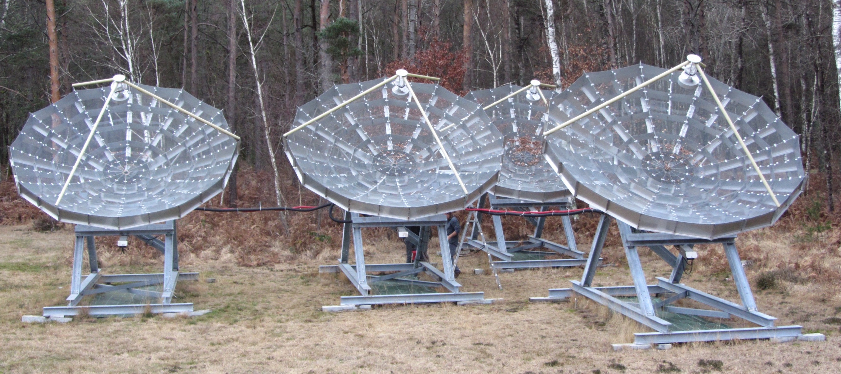
During a short test period from autumn 2012 to summer 2013 two 3 m diameter dishes were used for observation at Nançay. Meanwhile, the PAON4 reflectors were designed and manufactured. The mount and reflectors were assembled on site during the end of spring/summer 2014 and then equipped with the receivers and electronic modules in autumn 2014. First observations were carried out in winter 2015, and the instrument was formally inaugurated in April 2015. The four reflectors are visible in the photograph shown in Figure 1, taken from a point south-west of the array.
2.1 Array configuration
The PAON4 interferometer is composed of four 5 m diameter parabolic reflectors and has a combined geometric collecting area of ( effective area for ). It is hosted at the Nançay radio observatory333Nançay radio observatory, https://www.obs-nancay.fr/, in France, about 200 km south of Paris. The array (central antenna) is located at latitude , and longitude.
The PAON4 compact triangular configuration was selected after comparison of several possibilities. The chosen configuration provides 6 independent baselines, which is the maximum possible with 4 antennas, compared to 4 baselines for a rectangular configuration. Moreover, the beam of the triangular configuration has a much more circular shape than the , and its resolution is also slightly better than a single dish of 14 m diameter (Zhang et al., 2016b). Three dishes are positioned at the three vertices of an equilateral triangle with 12 m sides, while the fourth dish is located close to the center of the triangle. In addition to the four auto-correlations signals (zero length baseline), there are six independent baselines, as shown in the array layout schematic of Figure 2. One baseline (1-2) is aligned with the East-West direction, one baseline (3-4) lies along the North-South direction, and the four other baselines have both EW and NS components.
The receiver on each reflector is made of a cylindrical feed with two probes sensitive to two polarizations. The H-probe is sensitive to the electric field parallel to the EW direction, and the V-probe is sensitive to the field in the meridian plane. There are thus a total of 8 RF signals from the four feeds: Four H-polarization signals and four V-polarization. These are amplified, filtered, and frequency shifted to VHF band before being digitized. The digitized signals are processed in real-time by a a small cluster of acquisition computers which calculate all correlations. Two additional RF signals pass through identical analogue and digital electronic chains before being fed to the acquisition computer. The first one, called RFIMON, carries an RF signal from a a simple dipole antenna and is used to monitor the RFI environment in the PAON4 band. The second RF signal comes from a 50 resistor connected to the input of a LNA, identical to the one which equips the H and V probes. This RF signal, referred to as THERMON, is used to monitor the temperature dependent gain variations of the analogue electronic chain and correct for it. This is discussed further in Section 5. PAON4 also includes a standard temperature probe which is read every few minutes, providing temperature variations of the antenna environment. The mount, reflector and feed design is discussed hereafter, and the electronic chain and the software correlator are described in Section 3

2.2 Reflectors and feed design
The antennas were designed and built at the Observatoire de Paris GEPI laboratory and by industry subcontractors. The design has been chosen in order to fulfil the following requirements:
-
•
build four prototype antennas with 5 m diameter with a parabolic reflector;
-
•
build a robust antenna architecture to be able to sustain historical storm conditions in the region of Nançay (i.e. wind speed of km/h) as well as snow and ice during severe winter conditions;
-
•
permit the dish motor to orient in a broad range of elevation (declination) angles;
-
•
limit as much as possible the cost while ensuring reliable operations for 10 years or more.
Some design parameters are summarized in Table 1 and the whole array is shown in Figure 1.
The mechanical structures of the antennas are standard steel structure elements which underwent anti-corrosion treatment by hot-dip galvanizing, and were prepared (cut, drilled) by numerically controlled machines by the subcontractor. Each parabola is made of 12 petals for logistic reasons. Each petal is made of a laser-cut stainless steel sheet with a carefully hand-installed reflector mesh. About 600 hours were required to install the mesh at the GEPI laboratory. The surface deviations of the mesh were kept as low as possible, and they were measured after mounting at a level of /70 r.m.s.. This design is well adapted for a project on the scale of PAON4, but for a larger array a more automated process would be required since non-negligible manpower on site was required for the mounting of the 48 petals.
Asynchronous motors with reduction gears and non-reversible trapezoidal screws are used for the declination axis pointing. The rotation of the motor is selected by embedded software, and takes into account the stop phase duration for better pointing precision. The position of the parabola is controlled by an accelerometer which is installed in a sealed control command box and is therefore fully protected against the weather conditions, unlike the position encoders. In addition to performing pointing measurements, the accelerometer can monitor any small angular displacement of the antennas such as those due to possible ground instabilities. A running mean of 2000 samples is performed in order to measure the position of each parabola. The pointing of the antennas is controlled by scripts or by an embedded web server accessible through the internet. A precision of has been measured on site.
The PAON4 antennas are installed near the EMBRACE prototype (Torchinsky et al., 2016), and could therefore be easily connected to the electric mains and Ethernet network. At this place, the ground is particularly loose and in order to avoid having to build expensive and fixed concrete foundations, the antenna structures are slightly flexible with respect to horizontal stability, and are equipped with four legs in a statically undetermined configuration. In addition, the rotation axis bearings include kneecaps.
| Dish | |
| Diameter reflector | 5 m |
| f/D | 0.4 |
| L x W x H | 6 m x 5 m x 5.4 m |
| roughness(design) | at 21 cm |
| zenith angle | N to S |
| Total weight | 2200 kg |
| Feed & choke & probes | |
| Diameter “choke” | 360 mm |
| Height “choke” | 80 mm |
| Distance from entrance | 10 mm |
| Thickness | 1.5 mm |
| Diam. internal “feed” | 158 mm |
| (0.8 mm) | |
| Thickness | 4.5 mm |
| Height (total) | 377 mm |
| Probes | 2 (linear) |
| Probe (Diam./Length) | 6.2 mm/50.2 mm |
| Conic part of the probe | 2.5 mm |
| Distance probe-end cap | 79.2 mm |
| Base | N std. Radiall R 161 404 |
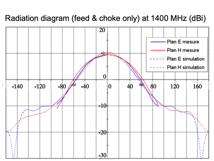
| Gain (meas./simu) | 9.5 dB/10.34 dB |
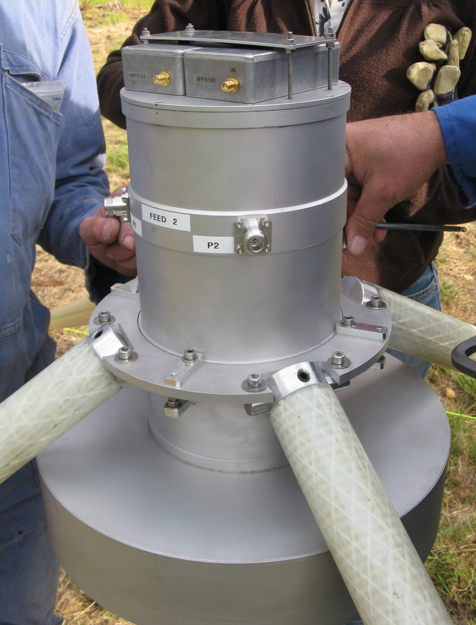
The feed design was adapted to the dish diameter, taking into account the needs of two orthogonal linear polarizations and the total bandwidth MHz. It uses a classical circular wave guide with a choke. The geometric parameters are listed in Table 1 and shown in the sketch of Figure 3 (left panel). The guide has a diameter of 158 mm and a length of 377 mm machined inside a aluminium guide 4.5 mm thick. The cut-off frequencies are 1110 MHz for the TE11 mode and 1460 MHz for the TM01 mode making the feed system single moded throughout the bandwidth except in the upper 40 MHz. The guide wavelength is mm at MHz. The machining guarantees a circular tolerance of (0.8 mm) for a cross-polarization isolation of dB. This feed is suitable for the PAON4 bandwidth but could not be easily adapted to a larger bandwidth. The probes are made with brass rods of relatively large diameter to have the possibility of larger bandwidth in the future. The conic shape of the rod minimizes the impedance mismatch with the base. The exact locations of the probes inside the circular guide have been optimized by simulation and verified by measurement a posteriori. The choke design has also been optimized by simulation to reduce side lobes as much as possible.
Figure 3 (right panel) shows the manufactured feed. The feed is maintained at the focal location by three fibreglass hollow bars to optimize the electromagnetic transparency of the supports while ensuring robustness during high wind conditions. The radiation diagram of the feed alone has been simulated and then measured with good agreement, as shown in Figure 4.
3 Electronic and acquisition system
PAON4 is equipped with the analogue and digital electronic modules developed in the BAORadio project which began in 2007, mostly as digital components for a 21 cm Intensity Mapping survey (Ansari et al., 2012a). The ADC boards are based on FPGA technology. Each is capable of digitising 4 RF signals at 500 MHz sampling rate, and performing an FFT in real time with 61 kHz frequency resolution (Charlet et al., 2011).
An analogue RF amplification, filtering, local oscillator, and mixer were designed and realized for testing the digital components boards with the PCT (Pittsburgh Cylindrical Reflectors). The LNA was specifically designed and made for PAON4. The electronic chain, and in particular the analogue components, were designed primarily for testing purposes and the performance does not equal the current state-of-the-art.
The BAORadio electronics and the associated data acquisition software were used several times on the PCT at Pittsburgh (Bandura, 2011). In 2010, 32 signals were processed from the PCT feeds, including the computation of the full set of 512 correlations, over a reduced band of . The same system was also used on the FAN project (Deschamps et al., 2013) and successfully deployed at the NRT (Nançay Radio Telescope) for the HICluster program, searching for in nearby clusters (Ansari et al., 2016).
3.1 Analogue and digital electronic
An overall schematic view of the PAON4 analogue electronics chain is shown in Figure 5.
The amplifier circuit consists of two LNA’s interconnected through a low pass filter. The amplifiers are installed at the feed. They are connected to the probes through cables. An Avago/Broadcom MGA633 GaAs MMIC ultra low noise amplifier is followed by a Qorvo SPF5122 LNA, and a low pass filter is inserted between the two LNAs to lower the power at the input of the second one. The total gain is and the noise factor , leading to a noise temperature of for the the first stage amplifier (). An cable connects the feed amplifiers to the second stage amplifier on the antenna. This stage consists of two SPF5122 LNA and provides an additional gain of , which is connected to the frequency shifter in the main analogue electronics cabinet on the central antenna with a second cable. After an RF filter, the signal is amplified before down conversion. An ADF4360–5 PLL and VCO frequency synthesizer delivers a signal to a JMS–11X frequency mixer. The signal is down converted to the VHF band. Additional VHF amplification is performed and a low pass filter ( at ) eliminates the high frequency part of the signal. The RF card output is connected to the ADC board in the EMBRACE (Torchinsky et al., 2016) container by two cables. A first cable brings the signal to the feedthrough panel at the container wall, followed by a cable from the feedthrough panel to the PAON4 digital electronics.

Each BAORadio ADC board includes two (ADC+FPGA) blocks sharing common control electronics. Each block handles two analogue inputs which are sampled at 500 Msample/s with 8-bit dynamic range. Each block transmits data through high speed optical links to dedicated PCIExpress reception boards in the acquisition computers. The eight PAON4 RF signals (4 H-pol + 4 V-pol) are thus digitised by two ADC boards, and data is transmitted via 4 optical fibres to the acquisition computers located a few hundred meters away. A third ADC board handles the RFIMON and THERMON channels, which are treated separately by the acquisition computer and do not go through the correlator. The ADC boards are configured and controlled through USB links and they receive a common master clock and trigger signals through dedicated connectors. Two different versions of the firmware can be loaded on the ADC board FPGA’s. The first one, called the RAW firmware is used to digitise signal and transmit waveforms to the acquisition computers. The RAW firmware can handle a maximum of 48k samples corresponding to long digitization frames. The second firmware, called the FFT firmware, performs waveform sampling, Fourier transform (FFT), clipping, and then transmits the Fourier coefficients (2 byte complex numbers) for 8k sample digitization frames corresponding to in time and 4096 Fourier coefficients with 61 kHz frequency resolution. Each digitization frame is time-tagged with the 125 MHz FPGA clocks and the digitization frames on different FPGA’s are synchronised by the external trigger signal. The BAORadio ADC boards can cope with a maximum trigger rate of , corresponding to on-sky time. However, the current acquisition computer system and software correlator can only cope with a trigger rate of , corresponding to on-sky time. We carried out observations with the FFT firmware in September and November 2016 (see Table 2), but the results discussed in this paper are mostly based on data taken with the RAW firmware. The digital data stream, either waveform or Fourier components are transferred over optical fibres to the software correlator-acquisition computer cluster located away, in the Nançay computer building.
3.2 Data acquisition and software correlator
The data acquisition system is composed of a cluster of computers located in a dedicated room in Nançay. They are interconnected through a private 10 Gbit/s Ethernet network. Communication to the outside world is done through the external 1 Gbit/s Ethernet network. An additional computer connected through the Nançay private network is located in the EMBRACE container. It is also on another dedicated network and controls a number of subsystems including power supplies, local oscillator (LO), as well as the thermometer readout. The same computer handles the control of the ADC boards through USB communication with the pointing controllers of the 4 antennas.
The acquisition/software correlator system itself is composed of 6 computing nodes and an additional machine acting as the acquisition controller and supervisor. The computing nodes are arranged in two layers: 4 of them form the first layer (front-end machines) which receive data from the two ADC boards, through four optical links. The two nodes forming the second layer perform the correlation computations. Figure 6 shows a schematic view of the system configuration. The acquisition and processing of the two ancillary RFIMON and THERMON signals is done by an independent computer running the same software.
The front-end machines perform FFT on the received data streams, except when the FFT firmware is used, and then divide the frequency bands into a number of sub-bands corresponding to the number of computing nodes in the correlator layer. Each front-end machine receives the data corresponding to two RF signals, currently arranged as a pair of polarization signals, H-H or V-V. Fourier components for each sub-band is sent to the corresponding compute node in the correlator layer which has two nodes, each computing 36 correlations for 2048 frequency channels over 125 MHz band which is half of the full ADC board Nyquist sampling limit of 250 MHz. The 36 computed correlations correspond to the following pairs:
-
•
8 auto-correlations, 4 corresponding to the H signals, and 4 to the V signals.
-
•
12 correlations corresponding to the cross correlations between the same polarization signals. There are 6 H-H and 6 V-V cross-correlations between H-polar and V-polar signals from the 4 feeds.
-
•
16 correlations corresponding to H-V cross-correlations between the H-polarization signal from one feed and the V-polarization signal from the second feed.
The total data rate ingested by the front-end machines at on-sky time corresponds to , with a factor 4 higher rate exchanged between the two layers, as the FFT computation is carried with 4-byte floating point numbers. Correlations are taken typically at a sampling rate of one or a few seconds. Most data discussed here was taken with a correlation sampling rate of 3 or 6 seconds. Computed correlations (also called “visibilities”) are saved into permanent storage (disk) every few seconds, and a number of visibility matrices, defined again by input parameters are grouped into a single file. A typical 24 hours observation run with 3 second visibility sampling rate produces around 70 GB of data, split into size files.
The data acquisition and correlator software, TAcq, was developed for the BAORadio project starting from 2007 and has been enhanced over the years. It is a flexible, high performance C++ software package, which uses the SOPHYA444 SOPHYA C++ class library : http://www.sophya.org/ class library for standard numerical algorithms and I/O. The flexibility and various operation modes allows TAcq to be used at different stages of the project, from final tests of the electronic system boards, to the routine operation of the interferometer, as well as during commissioning.
The TAcq package defines a simple and very efficient multi-threaded architecture, where different threads communicate through a central memory manager hub. The number of running threads is also dynamically determined through the parameters which are tuned to a given hardware configuration. A description of the software architecture, the different classes and system operation modes are beyond the scope of this paper and will be discussed in a separate, forthcoming publication.
In practice, a main program called mfacq with different operation modes, controlled by an extended set of parameters handles the acquisition and correlation computation tasks. The control node spawns one mfacq process in each of the compute nodes, the four front-end nodes and the two nodes in the correlator layer for PAON4, and provides each process their specific set of parameters. The complete system operates in streaming mode, with data packets exchanged between mfacq processes through the network layer. The time synchronization for visibility computation is ensured by the hardware time tags which are propagated through the data packet streaming protocol.

4 Operations and observations
After the completion of its construction (mid 2015), the PAON4 observations served several aims in successive periods, with few minor hardware or software changes. Observations carried out in 2015 were mostly dedicated to hardware debugging, from finding faulty cables and electronic modules to identifying some RFI sources. For example, an Ethernet switch was initially installed in the central antenna electronic cabinet, to ensure the readout of a temperature sensor, and was generating RFI. We also spent some time measuring correlated noise, both on the instrument and in the lab, in 2015 and 2016. Correlated noise measurements in the lab showed that the main source was by coupling through the power supply. The overall system was subsequently improved with better shielding, more careful ground wiring, and an improved power supply system. The correlated noise level was reduced by a factor 10 in this process. Gain variations and some randomly occurring perturbations were observed. Clarifying their sources and curing or correcting these effects consumed significant time and effort in 2017 and early 2018, as discussed in Section 5.
In May 2016, the 4V channel was terminated by connecting its front-end LNA to a 50 resistor. This was done as a diagnostic for understanding the source of perturbations (see Section 5.1) and gain variations (see Section 5.2). The 4V channel was reconnected antenna and the additional THERMON signal was added to the system in July 2018, after the identification of the perturbation source. In 2015 and 2016, we were operating PAON4 with the FFT firmware loaded on the ADC boards. The ADC boards were then sending FFT coefficients to the software correlator. We switched to the RAW firmware in February 2017, in order to investigate some problems with the FFT firmware, including possible saturation by satellite signals because of the limited dynamic range of the FFT firmware. We also added two front-end nodes to handle FFT computation by the acquisition/correlator software.
|
|
Data taking is automatic once all acquisition parameters are set, and can be remotely initiated and monitored. After each acquisition run, data are transferred to the IN2P3 computing center for analysis and archival. An SSH connection to the acquisition cluster is used for launching the data taking. It sets up the antenna and configures the digitization boards, and checks or modifies the acquisition parameters such as the visibility sampling rate, the observation ID, and the data set path on the master control node. The acquisition is started or scheduled to begin at a later time.
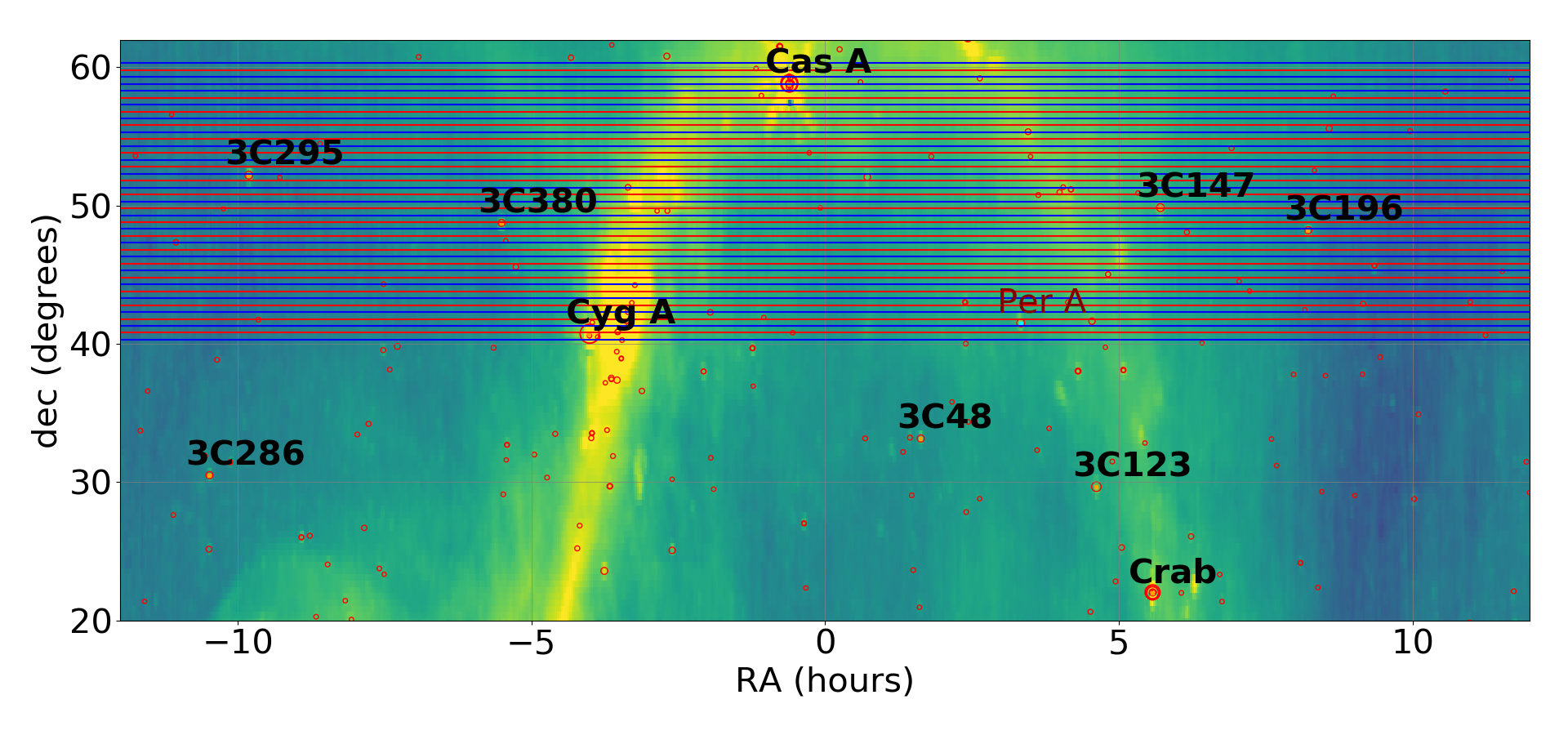
PAON4 instrument has been designed to survey a significant fraction of the northern sky, 3000-5000 , with full right ascension coverage, through a set of 24 hour constant declination scans. In fall 2016, we carried three mini surveys, observing declination ranges around the Cygnus A and Cassiopeia A bright radio sources with the FFT firmware. Details can be found in Table 2 and a more in-depth analysis can be found in (Huang, 2019). As mentioned above, observations from beginning 2017 until mid 2018 were motivated by the necessity to identify the source of perturbations. We started the first extended PAON4 survey in July 2018, covering about 20 degrees in declination, between the declinations of Cas A and Cyg A. More than forty 24-hour constant declination scans with 0.5 degree step were done from July to December 2018. The observations were split into two interleaved independent sets, labelled Scan_2018_A and Scan_2018_B. In each set, scans are separated by 1 degree step and the scans in B are shifted by 0.5 degrees with respect to the corresponding A scan. The scan pattern for Scan_2018 (A & B) data sets is shown in Figure 7. A number of additional problems have been identified by analysis of the Scan_2018 data, in particular imperfect packet synchronization by the ADC boards in some cases. The 2019 observation strategy was then targeted to further investigate these problems and to precisely characterise the instrument (pointing, lobe …) through long duration (LD), uninterrupted observations over several days. Table 2 summarises the characteristics of the different PAON4 data sets.
| DataSet | Period | declination (deg) | Nb.Scans | Duration | comment |
|---|---|---|---|---|---|
| CygA-Sep16 | Fall 2016 | 37…44 | 10 | 2 weeks | FFT firmware |
| CasA-Sep16 | Fall 2016 | 56…60 | 5 | 2 weeks | FFT firmware |
| CygA-Nov16 | Fall 2016 | 35…46 | 11 | 2 weeks | FFT firmware |
| Scan_2018 A | Summer 2018 | 40…60 | 20 | months | |
| Scan_2018 B | Fall 2018 | 40…60 | 20 | months | |
| LD_1 | January 2019 | 25, 30, 42, 58 | 4 | days | CasA, CygA, M1, VirA |
| LD_2 | April/May 2019 | 12…24 | 7 | 2 weeks | M1, Sun … |
| LD_3 | June,July 2019 | 35 | 1 | 10 days | CygA, stability checks |
| LD_4 | July 2019 | 12 , 22, 58 | 3 | weeks | CasA, M1, VirA |
5 Data processing
The data processing pipeline is composed of a set of C++ programs and python scripts which perform the tasks listed below. The visibility files are the input of the processing pipeline. They contain matrices, one matrix per visibility sampling time, where is the number of visibilities, and , the number of frequency channels, which are respectively and for PAON4. Most of the data analyzed here has a visibility sampling rate of 3 s or 6 s. The pipeline includes the following components:
-
1.
data quality monitoring and noise characterization.
-
2.
Determination and correction for time dependent electronic gain variations as well as frequency dependent gain .
-
3.
Production of time-frequency binned (TFM) or right ascension-frequency binned (RAFM) maps for the different visibilities.
-
4.
Phase and gain calibration using known sky sources, and determination of instrument parameters such as system temperature and beam response.
-
5.
RFI flagging and cleaning, mostly performed on TFM maps.
-
6.
Production of fully cleaned and calibrated time-frequency binned. (TFM) or ascension-frequency binned (RAFM) maps for the different visibilities which are then used by the subsequent analysis stages, in particular by the map making.
-
7.
Map making through different methods, including m-mode decomposition (see e.g. Zhang et al., 2016b)
The mathematical formalism for radio interferometer measurement equations and the calibration methods have been studied by many authors, including polarimetry issues (e.g. Hamaker et al., 1996; Sault et al., 1996; Smirnov, 2011). The numerical optimization problem has also been studied (e.g. Salvini & Wijnholds, 2014; Smirnov & Tasse, 2015) as well as their application to the calibration of large arrays such as LOFAR, MWA or HERA (Kazemi et al., 2011; van Weeren et al., 2016; Byrne et al., 2019). However, specificities of mid frequency arrays operating in transit mode have not yet been fully investigated.
In this paper, we focus on the first four stages of the pipeline, listed above. The discussion of subsequent stages and the maps produced from PAON4 observations is beyond the scope of this paper, and will be the subject of forthcoming publications.
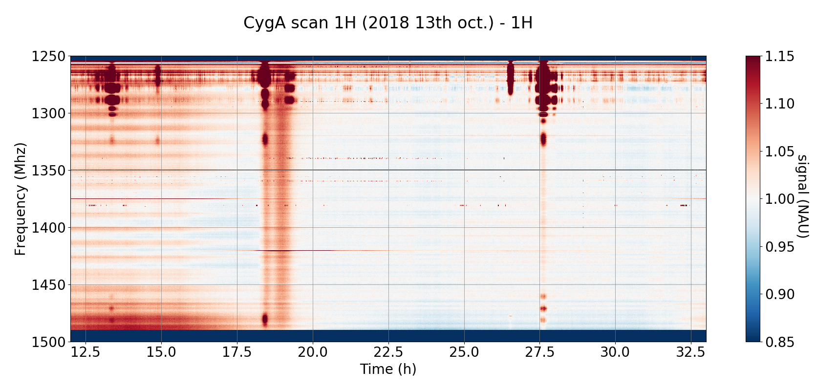
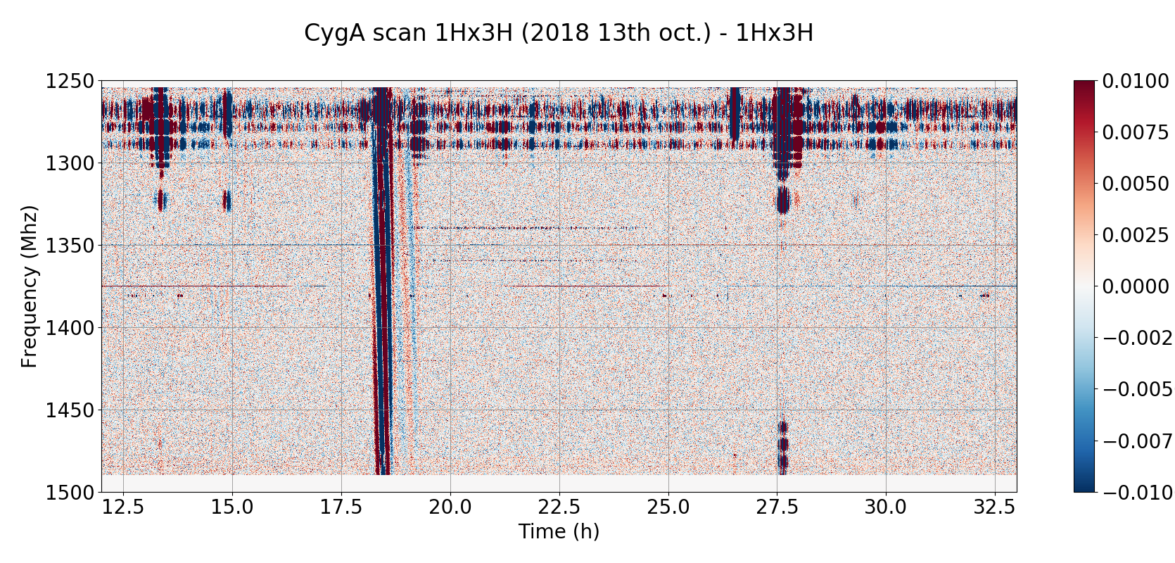
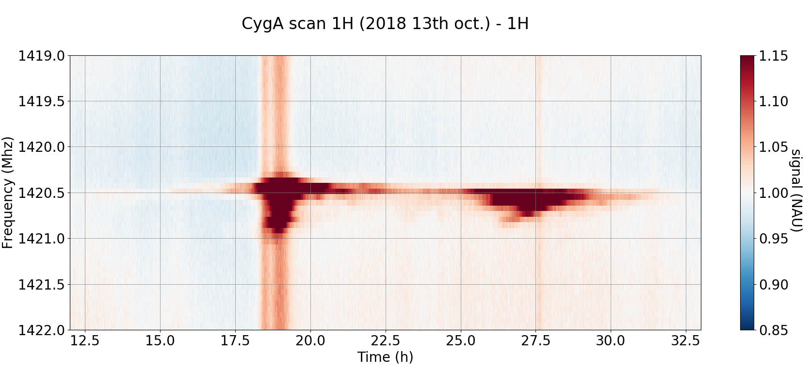
Typical time frequency maps (TFM) spanning 24 hours, obtained after a basic processing of PAON4 visibility data are shown in Figure 8. These maps were obtained from data taken on 2018 October 13, with antennas pointed toward the Cyg A declination at . The left panel shows the auto-correlation signal from the 1H channel. The strong pollution of the lower part of the frequency band, below by RFI, mostly from satellites, is clearly visible. The transit of bright sources, here Cyg A and the galactic plane, can be seen on the autocorrelation map. The galactic 21 cm emission around 1420 MHz is also visible, with the zoom around this frequency in the lower panel showing the galactic frequency dependent emission pattern. The right panel shows the cross-correlation signal from the (1Hx3H) feed pair. In addition to gain correction, an average frequency template corresponding to the correlated noise has been subtracted from the cross-correlation time-frequency map. The transit of the bright source is clearly visible with high signal to noise. Satellites are also visible in the lower frequency range.
 |
 |
5.1 External perturbations
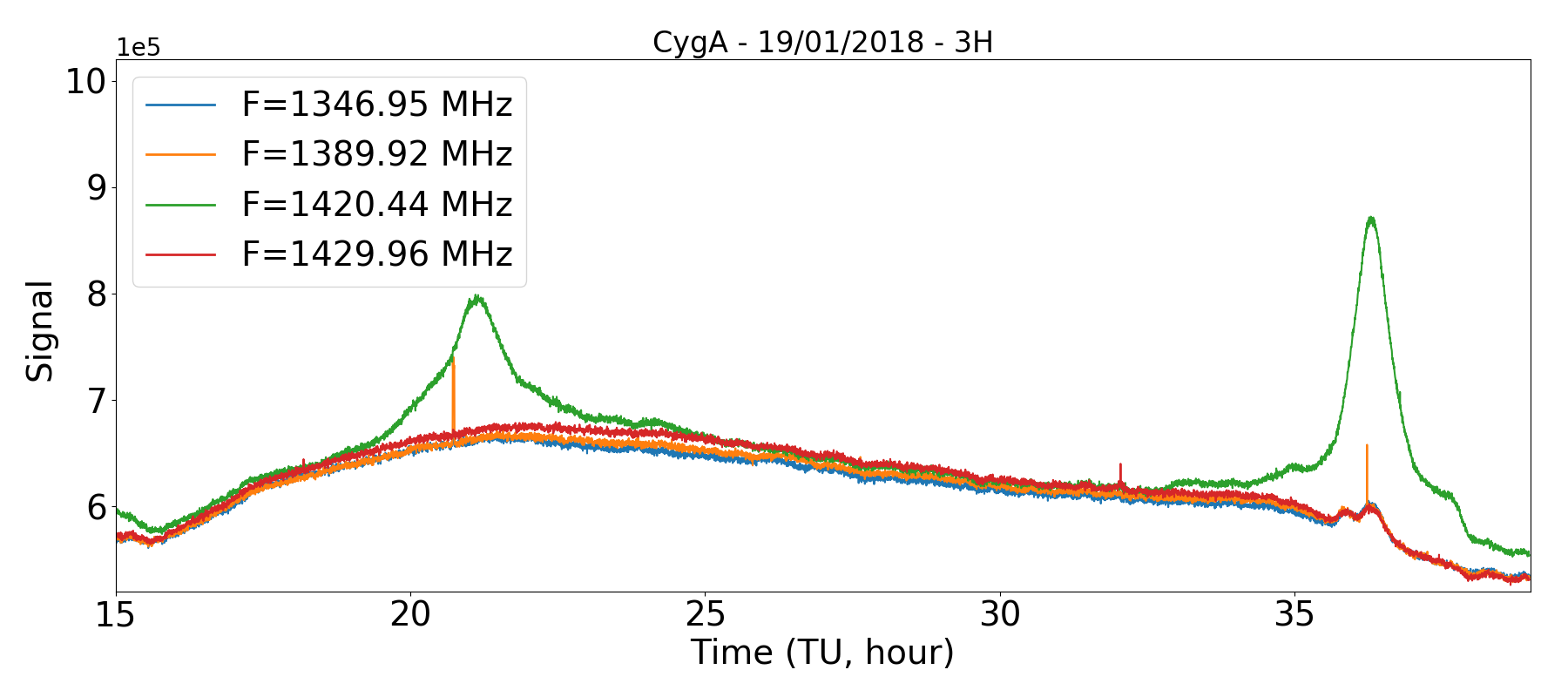
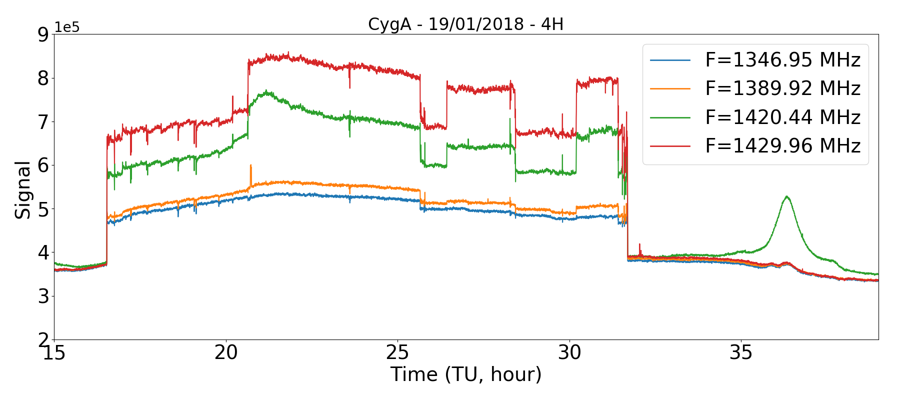
Before July 2018, PAON4 data were perturbed by a persistent artefact. Finding its origin occupied a major fraction of PAON4 observing time in 2017 as well as during the first semester of 2018. Sudden changes in the signal level were observed on a few of PAON4 signals. Figure 9 shows the variations of signal levels at four frequencies, for the 3H signal on the left, with normal behaviour, and the 4H signal on the right, exhibiting sudden level changes or jumps, at all four frequencies. On the normal 3H autocorrelation signal, one may observe a slowly varying trend, which is due to temperature induced gain variations, following day-night temperature changes. The transit of Cygnus A, at about 36 h (i.e. 12:00 UT), is visible on all frequencies except at 1420.44 MHz where 21 cm galactic emission dominates. In contrast with this normal behaviour, the perturbed 4H signal exhibits erratic variations, starting from a sharp rise at about 17 h and ending after a sharp fall at about 32 h (8:00 UT next day), with several intermediate positive or negative steps, at all frequencies. These perturbations were already seen on early PAON4 data, in 2015, but were more frequent during the 2017-2018 year. Investigating this effect during that year, we noted that:
-
-
The perturbation occurrence rate was % (i.e. 8 days out of 10)
-
-
Only one antenna was affected at a time
-
-
The most affected antenna was antenna 4, with a rate of about 80%. However, in 2015, whenever the effect was observed it affected only antenna 3
-
-
In the rare occurrences where one of the another antennas was affected, both polarizations were affected by similar (but not identical) perturbations, in exactly the same time interval. In the case of antenna 4, one of the two polarization probes on the feed, the 4V channel, was terminated from mid 2016 to mid 2018 by a resistor connected to the LNA input. No significant perturbation was ever observed on this terminated channel.
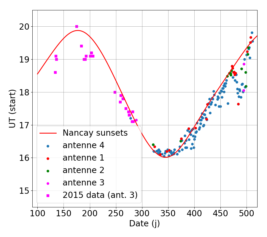
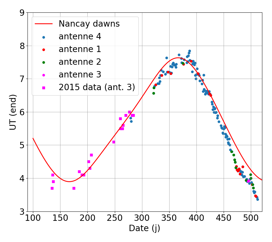
This last fact, combined with other checks through electronic modules and cable permutations showed that the perturbation had an external origin. Accumulating more data during the year brought another intriguing piece of evidence, displayed in Figure 10. The start and end times of the perturbation seemed to correlate quite well with the hour of the dawn and sunset in Nançay, although with some dispersion. After a long investigation campaign, we finally spotted in May 2018 a small bird spending its nights in the shielded environment of the chokes surrounding our feed. We concluded that the thermal radiation produced by the bird was the source of an additional signal during the night. We placed anti-bird nets around the chokes end of May 2018 which cured the problem.
 |
 |
5.2 Spectral response and time dependent gain
The PAON4 channel response varies both with time and frequency. We use in our analysis a simplified gain correction model by considering these two effects independently of each other, giving .
As a result of the combination of the various stages of frequency filtering, and signal transmission cables, the frequency response is complex (Figure 11). The gain shape is primarily determined by the LNA and pre-amplifier spectral response, but in the current design of the DAQ, the 50 m coax cables between the central dish and the digitization boards located in the EMBRACE container are responsible for the dramatic gain decrease above 1300 MHz. For each channel, the gain also shows wiggles that are attributed to standing waves in the 9 m cable between the LNA and the pre-amplifier and the 10 m cables between the pre-amplifier and the local oscillator electronics. The characteristics of these standing waves are time variable. The peak-to-peak wave separation, of the order of 12.5 MHz, is inversely proportional to the cable length which motivated the shortening of cables as much as possible. The R&D program began at this time with the aim of performing the analogue to digital conversion as close as possible to the LNA on the feed. This R&D program will result in the installation of new electronic boards called IDROGEN (see Section 7).


As mentioned above in Section 5.1, and shown in Figure 9 (right hand side), the raw PAON4 auto-correlation signals in each channel show a systematic drift in time with a day-night pattern. This is caused by the gain variations due to ambient temperature variations experienced by the analogue electronics chain. The analogue electronics are located outside without any environmental control system. The temperature stability of the PAON4 electronics chain was measured in the lab. There is 4 dB () gain variation for temperature varying between and . In the PAON4 setup, a range is expected, and with the sun shine effect, the daily amplitude of the temperature variation could easily reach and exceed leading to gain variations. The analogue electronics were not designed to be deployed without a temperature-controlled environment and this is an issue which will be improved in the next generation electronics design (see Section 7).
Using data taken in 2017 and 2018 with the resistor terminated 4V channel, we demonstrated that time variation of the signal of each channel, outside bright sky source transits times, was tightly correlated with the terminated channel. A gain variation model based on this correlation was then created and the terminated channel signal used to compute and correct for the time varying gain term of all other channels. The effect of gain variations decreased from to using this simple scheme. The 4V channel was reconnected in July 2018, and an additional resistor terminated channel, THERMON, was added to PAON4. This is now used to correct for gain variations. The gain corrected visibilities are expressed in NAU (Normalized Arbitrary Unit), with auto-correlation levels close to unity outside bright sources or sky transits.
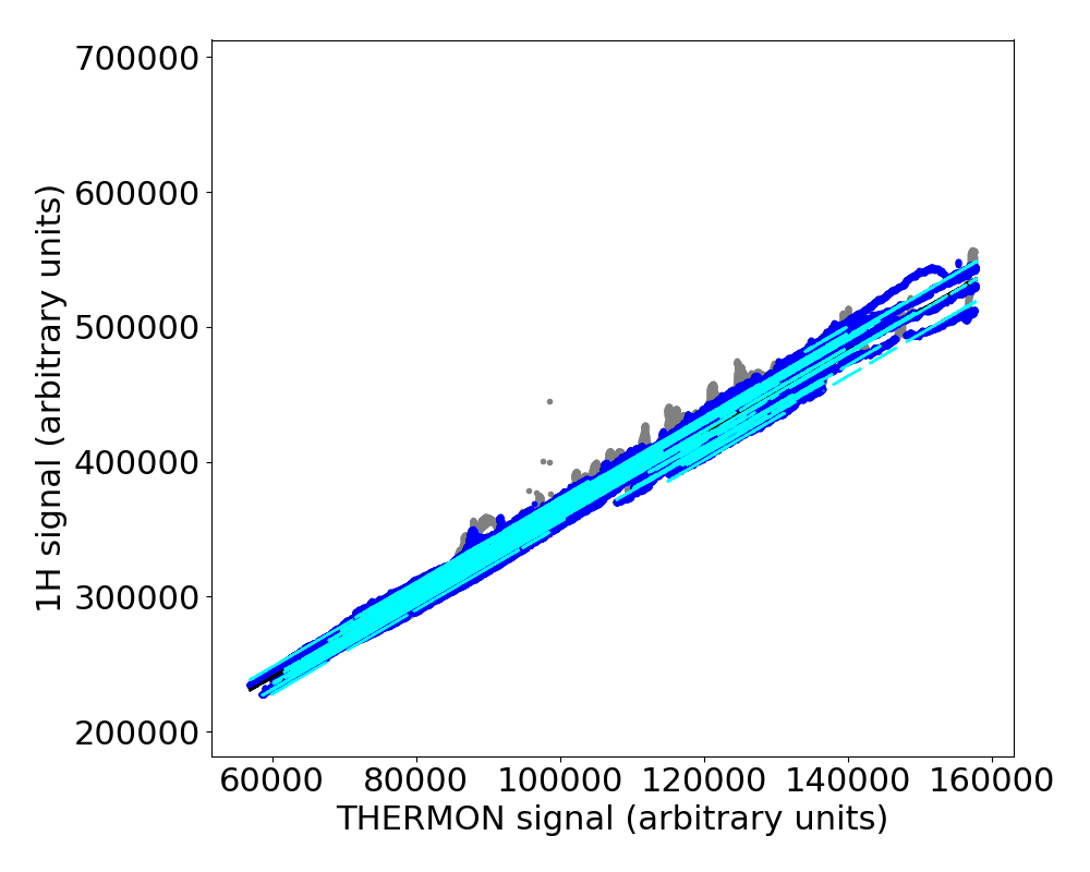
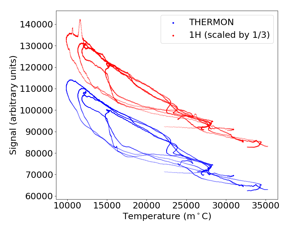
We determined for each channel the parameter of a linear correlation with the median of the signal (after satellite and source removal) and the THERMON signal (in the same time frame). We show in Figure 12 examples of this reconstruction for the 1H channel when analyzing data from the Scan_2018 A and B part simultaneously. A unique slope was fitted with different intercepts for each observation run. Once correcting for the linear variations, outlined in cyan, the signal variation amplitudes are reduced from to . The THERMON and the antenna channels are both correlated with a direct temperature measurement. This correlation has a large dispersion and shows hysteresis as a result of the different mechanical structures and the positioning of the temperature sensor (on top of the EMBRACE hut). Figure 12 shows that the THERMON signal provides a better template for correcting the temperature-induced signal variations than a direct temperature measurement. Evidence of a residual hysteresis may be seen on the left panel, which could be explained by the thermo-mechanical differences between the LNA’s on the feeds and the lighter THERMON set-up, leading to faster temperature variations for the latter.
 |
 |
5.3 On sky calibration
Point sources on sky are used to determine the instrumental phases, as well as the antenna beam and overall radiometric calibration. The PAON4 survey strategy includes regular observation of bright sky sources, such as Cassiopeia A (Cas A) and Cygnus A (Cyg A), every few days to obtain gain and phase calibration parameters which are then used for the subsequent scans and to update the instrument model.
The primary calibration source is Cas A which can be considered a point source for PAON4. A simple model is used to represent expected auto-correlation and cross correlation signals from Cas A, and we fit instrumental phases, amplitudes, as well as beam shape parameters. Also fitted is the effect on the auto- and cross-polarizations for H and V due to changing the pointing direction along the East-West direction. For each polarization, H or V, independently from each other, the parameters are adjusted on the set of 4 auto-correlations and 6 cross-correlations signals, for each binned frequency channel. The cross-correlations between two orthogonal probes HV are not included, ignoring source polarization. After fitting the auto-correlations which notably fix the beam shape parameters, the 6 cross-correlations signals are used to determine relative phases between the feed on antenna 1 taken as reference and the 3 other feeds (i.e with ). There are degeneracies between the instrumental phases and the relative phases induced by the array geometry, which is fixed at this stage. We have refined PAON4 antenna positions, determined from geometrical measurements during PAON4 deployment, using satellite transits as described below.
The lower part of PAON4 band, below is heavily polluted by satellite emissions, dominated by positioning satellites from the GPS (US), Galileo (EU) and Beidou (China) constellations. In particular, PAON4 sees a strong signal from Galileo E6 band, centred at , as well as from Beidou in the same band. Although GPS do not have direct emission in PAON4 band (), we do see the GPS L2 signal centred around , at the symmetric frequency of , with respect to the LO frequency at . These satellite signals are used for determining PAON4 geometry, beam shape, and instrumental phases. Several satellite tracks are usually present in our daily (24 hour) observations. We developed an additional software module included in our pipeline which uses satellite tracks computed using the SGP4555https://www.danrw.com/sgp4/ library from NORAD666https://www.norad.mil TLEs (Two Line Elements) available from CELESTrak777http://www.celestrak.com/NORAD/elements, as well as tracks of celestial objects at different frequencies, separately for each polarization. The module performs the following operations:
-
1.
Determine the pointing directions, as well as parametrised beam shape for each PAON4 antenna, using auto-correlation signals and the satellite tracks. It should be noted that the satellite signals are very strong. Galileo satellites are a few hundred times brighter than Cas A.
-
2.
Using the parameters determined above, the phases are determined for each baseline separately. It is also possible to determine the phases from a combined fit over the six baselines and multiple frequencies using a linear frequency dependent phase model .
-
3.
The derived instrumental phase variations as a function of pointing directions are used to refine PAON4 antenna positions along the vertical direction () and the North-South direction, as discussed in Section 6. The positions along the East-West direction changes the fringe rate and a combined fit, using visibility data from different declinations and many sources is used to obtain precise array geometry.
-
4.
Among the fitted parameters are the source amplitudes. The source amplitudes for Cas A and Cyg A are used to determine PAON4 radiometric calibration factors (Kelvin/NAU), to convert gain corrected visibilities to temperature. Instrument gain stability is also discussed in Section 6.
6 Instrument performance
The analysis presented here is based on data taken in fall 2016, fall 2018, and winter and spring 2019. The precision of calibration parameters, stability, and overall instrument performance are discussed here.
6.1 System temperature and radiometric calibration stability
The transit of Cas A, Cyg A, and satellites are used to determine the antenna temperature of the 8 polarizations (H and V for each antenna). Two procedures are used. The first one, (a), uses satellite tracks and Cas A and Cyg A transits and are applied to data from the 2019 long duration observations. The dish diameter in this procedure is determined from the autocorrelation signals using satellite transits, while the bright source maximum amplitude is obtained by fitting the cross-correlation signal between two signals of the same polarization (ie. H-H or V-V cross-correlation only). In the second procedure, (b), the auto-correlation signals during the Cas A transit are used to derive the maximum signal amplitude and the effective dish diameter for a given dish and polarization. This second procedure is applied to the Cas A transits during the (A,B) periods (Table 2). A Gaussian beam approximation is used in the procedures. Time-frequency maps produced after the gain correction lead to gain corrected autocorrelation signal levels very close to 1 NAU, except during source or satellite transits.
The fit coefficients are converted into radiometric calibration coefficients in units of and in units of . This is done using the Cas A and Cyg A spectral flux reported in Perley & Butler (2017). Cas A has an intensity of Jy and Jy at 1440 MHz and 1396 MHz respectively. Cyg A has an intensity of Jy at 1396 MHz. The radiometric calibration coefficient in normalized units NAU is related to temperature in Kelvin using the source intensity according to
| (1) |
| Polar. | |||
|---|---|---|---|
| (a) | (a) | (b) | |
| 1H | 116 | 147 | 144 |
| 2H | 127 | 129 | 133 |
| 3H | 130 | 122 | 138 |
| 4H | 161 | 152 | 185 |
| 1V | 113 | 100 | 103 |
| 2V | 108 | 92 | 100 |
| 3V | 103 | 111 | 98 |
| 4V | 143 | 151 | 180 |
With no strong sources in the field, signal levels are around 1 NAU. The value of the calibration coefficient is then equal to the system temperature reported in Table 3. We have used two procedures applied to different data sets to determine effective dish diameters and radiometric calibration.
Procedure (a) operates at 1396 MHz to determine the system temperature. It uses the satellite tracks at 1278.75 MHz to fit the effective dish diameters and pointing parameters with the assumption that they do not vary too much over the bandwidth. The radiometric calibration is then determined from fitting the 12 cross-correlation maximum intensities during bright source transits. This procedure is applied to Cas A and Cyg A transits separately, during a single, although long period of observation.
Procedure (b) is applied independently to visibilities at different frequencies, with results at 1440 MHz reported in Table 3. It fits at once the maximum intensity, the effective diameter, and the azimuth misalignment of the dishes using the 8 auto-correlations during the 8 Cas A transits, with observations scattered over several months. With method (b) we note that the effective diameter exhibits sinusoidal variations around as a function of frequency due to standing waves between the reflector and the feed. These variations represent a phase shift between the H and V polarizations.
Table 3 summarizes the different values of the antenna temperatures. We estimate a relative uncertainty of 10% mainly due to the maximum intensity and the effective diameter errors. The stability level is better than 10% based on measurements performed over several months.
The results show a tendency for dish number 4 to be more noisy which may be due to the fact that this dish is the closest to the surrounding trees. The H-polarization feeds are about 20% noisier than the V-polarization feeds (, ). The origin of this difference between H and V feeds is not yet understood.
The total noise temperature is . Electronic noise contributes (see section 3.1). Inefficiency of the mesh reflector adds noise since it permits some ground thermal emission through. Further studies will be done to clarify the source of additional noise contributions.
6.2 Noise characterization
Given the ratio between the noise level and the expected cosmological 21 cm signal, which is essentially stochastic, characterizing the noise and the way fluctuations decrease with integration time is a central question for IM instruments. Interferometry has the intrinsic advantage of being rather immune to variations of individual receiver noise levels. However, correlated noise would limit the theoretical sensitivity expected from a combination of visibility signals with long integration time. Moreover, interferometric arrays designed for IM surveys are closely packed, which increases the concern for the correlated noise between receivers due to electromagnetic coupling between feeds. We have studied the noise behaviour of our complete electronic chain, including the digitizer boards in laboratory, and identified some coupling sources, responsible for correlated noise, such as the coupling through the power supplies.
For more than a year up to July 2018, data were taken with a terminated 4V signal, where the input of the amplifier on the 4V feed was connected to a resistor (see Section 5). These data were used to help identify the sources of various perturbations, including the one subsequently identified as being due to a bird. They were also used to study the correlated noise, comparing visibilities involving the 4V signal with other signal pairs.
Our conclusions, from a preliminary study of the correlated noise, are summarized below.
We analyzed data from the January 2018 observations and computed time frequency maps with frequency resolution and 12 minute time bins, corresponding to an effective per pixel integration time of . Dispersions on the visibility signals (real/imaginary parts) were then computed over clean sections of the TFM maps, covering hours in time and , excluding bright regions of the sky. A noise reduction factor is expected. The r.m.s. values quoted below assume that the signals have been normalized to get auto-correlation levels equal to unity (for fields without bright sources).
-
•
The noise level observed for signal pairs involving the terminated 4V signal (1V-4V , 1H-4V …) are compatible with the levels expected given the integration time and frequency bandwidth, leading to . The correlated noise contribution can be considered negligible, at least for the integration times of the current analysis.
-
•
For the same polarization signal pairs between two different dishes, such as (1H-3H) or (1V-3V), the observed noise level is higher compared to the expected level, assuming Gaussian uncorrelated noise. We measure dispersions up to 4-5 times higher, .
-
•
For two cross polarization probes located in the same feed/dish such as (1H-1V) or (3H-3V), the dispersion level increases to more than .
The observed extra noise observed on the same polarization probes in two different feeds, or two probes within the same feed shows up as frequency dependent patterns, quite stable in time over a few hours. In can be interpreted as noise generated in the analogue electronic chain, cross fed through electromagnetic couplings between feeds on two different dishes, or between probes in the same feed, and then amplified in a way analogous to the Larsen effect. Fortunately, it can be efficiently subtracted due to its stability in time. Further studies are needed to determine the noise floor due to this correlated noise.
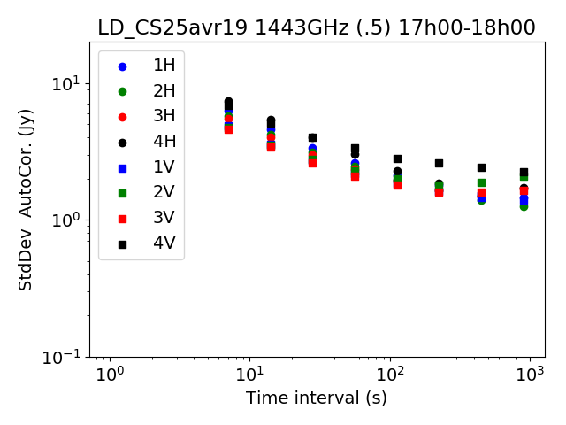
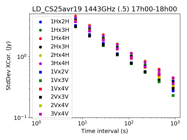
We have also analyzed how the noise level decreases with the integration time. Here, time frequency maps with different effective per pixel integration times are computed, with a fixed frequency bin width , from April-May 2019 data. Maps with different averaging time window sizes, equal to (1,2,4,8,16,32,64,128) in units of visibility sampling time are built and then used to compute signal dispersions (in the absence of bright source transits or RFI). Data from spring 2019 was taken with a visibility sampling time of 6 s leading to a maximum visibility averaging time of 768 s. PAON4 was operated with on sky efficiency so the maximum effective integration time is slightly above one minute.
Figure 13 shows the evolution of dispersion levels computed as the r.m.s. of the different time-frequency maps, excluding bright sources, satellites and RFI. The correlated noise is subtracted from the cross-correlation time-frequency maps, using the frequency template obtained by the time averaged signal, computed separately for each cross-correlation. The left panel shows the evolution of the dispersion with the integration time, for the 8 PAON4 autocorrelation signals. The r.m.s. decreases with the integration time, following a trend. A noise floor or saturation starts to appear at long integration times, more or less strongly dependent on the data set and the auto-correlation signal. However, it should be kept in mind that the r.m.s of the autocorrelations signals is sensitive to gain variations with time, as well to the variation of the diffuse sky brightness. The presence of this apparent noise floor for the autocorrelation signals does not imply that the underlying noise is not white. The right panel shows the evolution of the r.m.s. values computed on the cross-correlation visibilities (real part) for the 12 H-H and V-V correlations. Here, the r.m.s. values are compatible with the expected levels, and decrease with integration time following the expected white noise law , without significant contribution from correlated noise, once the average level at each frequency has been subtracted.
 |
 |
6.3 Phase calibration and array geometry
As mentioned in Section 5.3, Galileo satellites are used to perform phase calibration and determine instrumental phases for a large fraction of PAON4 observations carried out in fall 2018, winter and spring 2019. Instrumental phase values are determined for each constant declination scan. Figure 14 shows the antenna-2 phase values, determined at for 17 scans and the H-polarization feeds, as a function of the common, nominal antenna direction in the meridian plane, referred to as the zenith angle . This angle corresponds to the angle between the antenna axis and the local vertical, or the difference between the observed declination and the instrument latitude. Negative zenith angles correspond to the antenna tilted toward the south. One can see that the phase varies over more than , with a smooth variation as a function of the zenith angle. The variation is well explained by a shift in theoretical antenna position, along the north-south and vertical directions. The fitted best model, taking into account the baseline shift, is shown as the red curve. The fit result shows that the two feed heights differ by about for this (1H-2H) baseline, while the north-south component of this baseline should be corrected by . Using the 6 baselines, we determined the corrections to the array geometry, using the zenith dependency of the instrumental phases. We obtain a precision of using these 17 scans. A shift in the east-west baseline component would not show as a zenith angle phase dependency, but rather as a change in the fringe rate. We have not yet determined baseline corrections along the east-west direction using the fringe rates, but higher precision is expected for the determination of the east-west baseline corrections. The instrumental phases do not change by more than despite the fact that the observations were done over a period spanning more than 8 months. Similar phase stability is observed for the other baselines.

6.4 Comparison of observed and expected signals
 |
 |
 |
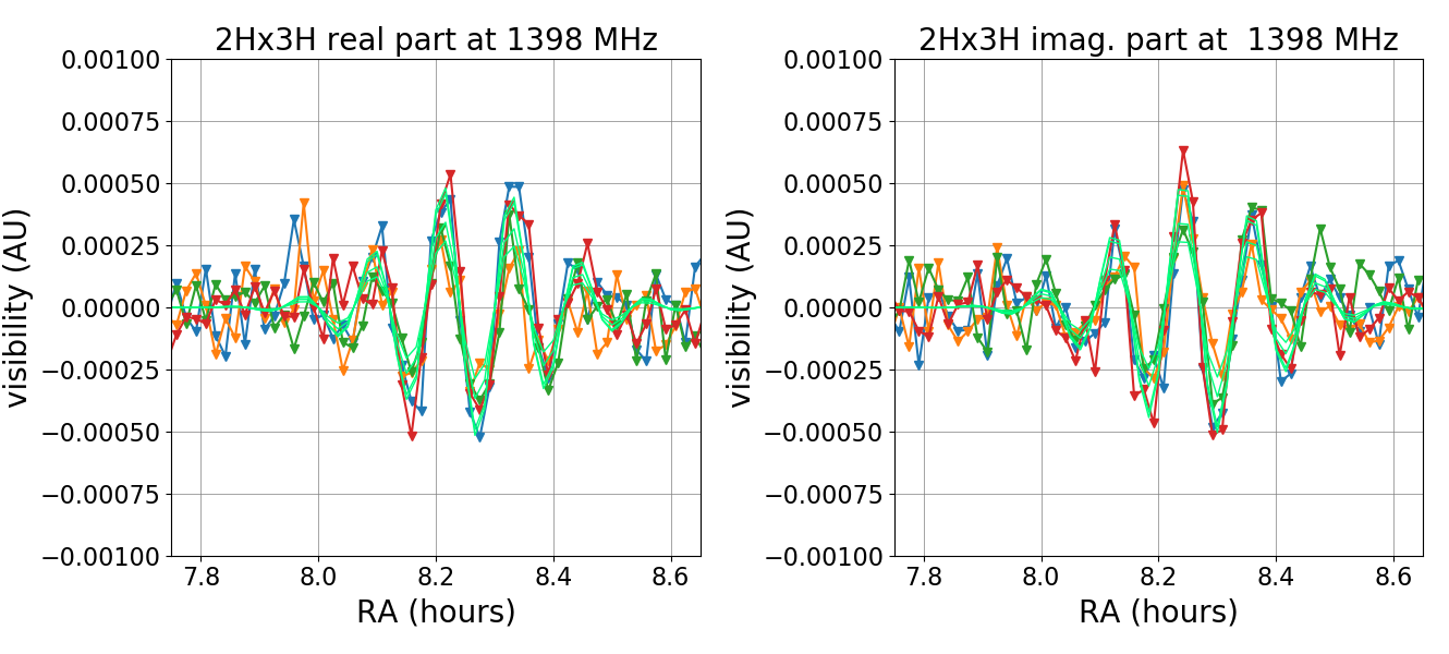 |
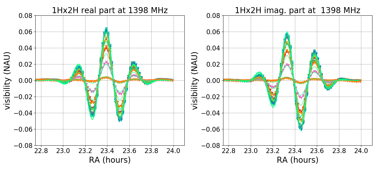
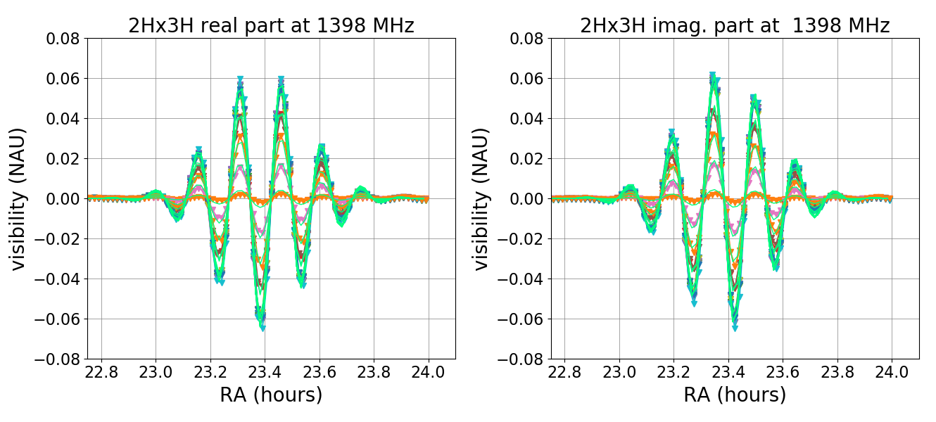
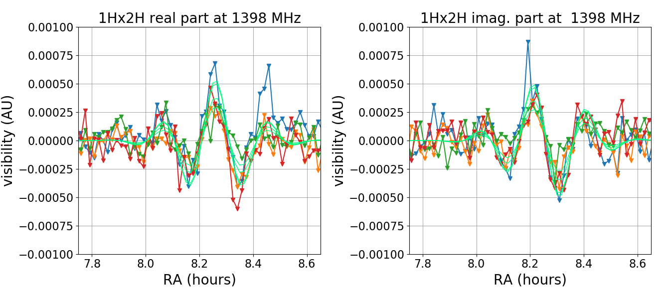
Figure 15 shows a comparison of observed and expected visibilities for a few scans close to two bright sky sources, Cas A (1700 Jy) and 3C196 (15 Jy) for the cross-correlation of two pairs of feeds, 1H-2H and 2H-3H. We gathered data from scans at several declinations around the source, represented in different colors. The visibility amplitude decreases for scans at more distant declinations with respect to the source declination. This effect is clearly visible Cas A, but also for 3C196. The expected signal was rescaled using a single conversion coefficient per feed, used for both sources, computed by adjusting the amplitudes of the expected Cas A on-source scan of July 17th, 2018. This simplified computation of expected signals does not take into account pointing uncertainties, whereas a shift is suggested by our satellite fits. Nor does it take into account the non-Gaussian secondary lobes in the beam pattern. The full signal level for Cas A is expected to be about , and for 3C196, while the noise level is about given the time and frequency binning used here.
Figure 16 shows a region of the reconstructed map at 1400 MHz using PAON4 observations from November 16th to December, 1st 2016. A map making applying the m-mode decomposition in harmonic space from transit visibility code, is used (Huang, 2019). A sky map covering the full 24 hour right ascension, and the declination range is computed from 11 24-hour constant declination scans around the Cyg A declination. The extracted map covers in declination and in right ascension around the nearby radio galaxy Cyg A. The emission from Cyg A, the Milky Way synchrotron emission, as well as from the Cygnus X star forming region, is clearly visible.

7 Future prospects
Time-variable systematics in the frequency response led us to develop a new generation of sampling and signal processing board, IDROGEN/NEBuLA, to perform digitisation as close to the feeds as possible (see Section 5.2). The IDROGEN board is designed to equip interferometers with several hundred feeds, scattered over a few hundred meters. Clock synchronisation is managed by the implementation of the White Rabbit888https://white-rabbit.web.cern.ch technology. A first version of this new board, called NEBuLA (NumEriseur a Bande Large pour l’Astronomie) was designed and produced in 2016-2017. The second version, called IDROGEN, is developed as part of the CNRS/IN2P3 DAQGEN project. This project began in 2017 with the goal of developing generic modules for rapid acquisition systems for particle and astro-particle projects.
IDROGEN boards will be located in the electronic boxes on each antenna, sampling the RF signals, relieving the need for frequency shifting, and transmitting the digital streams over optical fibres all the way to the computer cluster a few hundred meters away. The deployment of IDROGEN boards on PAON4 is foreseen in spring 2020, after more in-depth characterisation of PAON4 in its present configuration. A reduction of the amplitude of the temperature dependent gain variations is also expected because the analogue chain is simplified and does not have the downconversion stage. It also has improved passive cooling.
Upgrades of the acquisition system hardware and software are also planned with the deployment of IDROGEN boards and should enable PAON4 to reach to on-sky time which is a significant improvement compared to the current performance of (see Section 3). In particular, GPU support will be added to the TAcq package for the correlation computing software processor and also to the FFT processor to increase the system throughput. First tests will be performed in the current operation mode of PAON4. At a later stage, the new digitiser boards will be operated and qualified in the FFT mode. After those tests, we expect to release a stable version of the TAcq software, with full support for IDROGEN boards.
8 Conclusions
A densely packed dish array interferometer is a cost effective option to build radio instruments to survey large sky areas in L-band. We have built and operated the PAON4 dish array transit interferometer under very tight budget constraints. Preliminary results indicate that this type of instrument together with its associated observing strategy are effective both in terms of scientific analysis and cost effectiveness. The study presented here will progress further to longer integration times in order to demonstrate that the expected sensitivities at the few mK level can be achieved. In-depth studies with more data and PAON4 maps will be published in the coming year. PAON4 does not have redundant baselines, and the additional possibilities offered by the combination of nearly identical baselines will be explored with larger instruments. Such studies are being pursued in parallel with the Tianlai dish array. The next generation IDROGEN digitizer/signal processor boards are in the final stage of development and will be suited for a dish interferometer consisting of a few hundred feeds and baselines. IDROGEN will be deployed for qualification on PAON4 in 2020 and we plan to carry a higher sensitivity survey in the declination range in 2021. The resulting 3D maps will be useful to characterize the spectral behaviour of the galactic foregrounds, including a determination of its smoothness on the few MHz scale.
Acknowledgements
The deployment of PAON4 and observations at Nançay would not have been possible without the help and support of the technical staff of the Nançay Radio Observatory, which is the Unité scientifique de Nançay (USN) of the Observatoire de Paris, associated as Unité de Service et de Recherche (USR704) to the French Centre National de la Recherche Scientifique (CNRS). The Nançay Observatory also gratefully acknowledges the financial support of the Conseil régional of the Région Centre in France. We acknowledge financial support from “Programme National de Cosmologie and Galaxies” (PNCG) of CNRS/INSU, France.
References
- Abbott et al. (2018) Abbott T. M. C., et al., 2018, MNRAS,
- Abdalla & Rawlings (2005) Abdalla F. B., Rawlings S., 2005, MNRAS, 360, 27
- Amendola et al. (2013) Amendola L., Kunz M., Motta M., Saltas I. D., Sawicki I., 2013, Phys. Rev. D, 87, 023501
- Ansari et al. (2008) Ansari R., Le Goff J. ., Magneville C., Moniez M., Palanque-Delabrouille N., Rich J., Ruhlmann-Kleider V., Yèche C., 2008, preprint, (arXiv:0807.3614)
- Ansari et al. (2012a) Ansari R., Campagne J.-E., Colom P., Magneville C., Martin J.-M., Moniez M., Rich J., Yèche C., 2012a, Comptes Rendus Physique, 13, 46
- Ansari et al. (2012b) Ansari R., et al., 2012b, A&A, 540, A129
- Ansari et al. (2016) Ansari R., Campagne J. E., Colom P., Ferrari C., Magneville C., Martin J. M., Moniez M., Torrentó A. S., 2016, Experimental Astronomy, 41, 117
- Armstrong et al. (2009) Armstrong R., Hickish J., Zarb Adami K., Jones M. E., 2009, in Wide Field Astronomy & Technology for the Square Kilometre Array. p. 45 (arXiv:0912.0380), doi:10.22323/1.132.0045
- Bandura (2011) Bandura K., 2011, PhD thesis, Carnegie Mellon University
- Bandura et al. (2014) Bandura K., et al., 2014, in Ground-based and Airborne Telescopes V. p. 914522 (arXiv:1406.2288), doi:10.1117/12.2054950
- Bandura et al. (2019) Bandura K., et al., 2019, arXiv e-prints, p. arXiv:1907.12559
- Battye et al. (2013) Battye R. A., Browne I. W. A., Dickinson C., Heron G., Maffei B., Pourtsidou A., 2013, MNRAS, 434, 1239
- Betoule et al. (2014) Betoule M., et al., 2014, Astron. Astrophys., 568, A22
- Bigot-Sazy et al. (2015) Bigot-Sazy M. A., et al., 2015, MNRAS, 454, 3240
- Bigot-Sazy et al. (2016) Bigot-Sazy M.-A., et al., 2016, in Qain L., Li D., eds, Astronomical Society of the Pacific Conference Series Vol. 502, Frontiers in Radio Astronomy and FAST Early Sciences Symposium 2015. p. 41 (arXiv:1511.03006)
- Braun et al. (2015) Braun R., Bourke T., Green J. A., Keane E., Wagg J., 2015, Advancing Astrophysics with the Square Kilometre Array (AASKA14), p. 174
- Bull et al. (2015a) Bull P., Camera S., Raccanelli A., Blake C., Ferreira P., Santos M., Schwarz D. J., 2015a, Advancing Astrophysics with the Square Kilometre Array (AASKA14), p. 24
- Bull et al. (2015b) Bull P., Ferreira P. G., Patel P., Santos M. G., 2015b, ApJ, 803, 21
- Bull et al. (2016) Bull P., et al., 2016, Physics of the Dark Universe, 12, 56
- Byrne et al. (2019) Byrne R., et al., 2019, ApJ, 875, 70
- Chang & GBT-HIM Team (2016) Chang T.-C., GBT-HIM Team 2016, in American Astronomical Society Meeting Abstracts #227. p. 426.01
- Chang et al. (2008) Chang T.-C., Pen U.-L., Peterson J. B., McDonald P., 2008, Physical Review Letters, 100, 091303
- Chang et al. (2010) Chang T.-C., Pen U.-L., Bandura K., Peterson J. B., 2010, Nature, 466, 463
- Charlet et al. (2011) Charlet D., et al., 2011, IEEE Transactions on Nuclear Science, 58, 1833
- Chatterjee et al. (2017) Chatterjee S., et al., 2017, Nature, 541, 58
- Chen (2012) Chen X., 2012, in International Journal of Modern Physics Conference Series. pp 256–263 (arXiv:1212.6278), doi:10.1142/S2010194512006459
- Cosmic Visions 21 cm Collaboration et al. (2018) Cosmic Visions 21 cm Collaboration et al., 2018, arXiv e-prints,
- DES Collaboration et al. (2018) DES Collaboration et al., 2018, arXiv e-prints,
- Das et al. (2018) Das S., et al., 2018, in Millimeter, Submillimeter, and Far-Infrared Detectors and Instrumentation for Astronomy IX. p. 1070836 (arXiv:1806.04698), doi:10.1117/12.2313031
- Deschamps et al. (2013) Deschamps H., et al., 2013, IEEE Transactions on Nuclear Science, 60, 3620
- Furlanetto et al. (2006) Furlanetto S. R., Oh S. P., Briggs F. H., 2006, Phys. Rep., 433, 181
- Hamaker et al. (1996) Hamaker J. P., Bregman J. D., Sault R. J., 1996, A&AS, 117, 137
- Hinshaw et al. (2013) Hinshaw G., et al., 2013, ApJS, 208, 19
- Huang (2019) Huang Q., 2019, PhD thesis, Paris-Saclay University & University of Chinese Academy of Science
- Kazemi et al. (2011) Kazemi S., Yatawatta S., Zaroubi S., Lampropoulos P., de Bruyn A. G., Koopmans L. V. E., Noordam J., 2011, MNRAS, 414, 1656
- Masui et al. (2013) Masui K. W., et al., 2013, ApJ, 763, L20
- Newburgh et al. (2016) Newburgh L. B., et al., 2016, in Ground-based and Airborne Telescopes VI. p. 99065X (arXiv:1607.02059), doi:10.1117/12.2234286
- Parsons et al. (2010) Parsons A. R., et al., 2010, AJ, 139, 1468
- Perera et al. (2019) Perera B. B. P., et al., 2019, MNRAS, 490, 4666
- Perley & Butler (2017) Perley R. A., Butler B. J., 2017, The Astrophysical Journal Supplement Series, 230, 7
- Peterson et al. (2006) Peterson J. B., Bandura K., Pen U. L., 2006, arXiv Astrophysics e-prints,
- Peterson et al. (2009) Peterson J. B., et al., 2009, in astro2010: The Astronomy and Astrophysics Decadal Survey. (arXiv:0902.3091)
- Planck Collaboration et al. (2016) Planck Collaboration et al., 2016, A&A, 594, A13
- Planck Collaboration et al. (2018) Planck Collaboration et al., 2018, arXiv e-prints, p. arXiv:1807.06209
- Pober et al. (2014) Pober J. C., et al., 2014, ApJ, 782, 66
- Pritchard & Loeb (2008) Pritchard J. R., Loeb A., 2008, Phys. Rev. D, 78, 103511
- Salazar-Albornoz et al. (2017) Salazar-Albornoz S., et al., 2017, MNRAS, 468, 2938
- Salvini & Wijnholds (2014) Salvini S., Wijnholds S. J., 2014, A&A, 571, A97
- Sault et al. (1996) Sault R. J., Hamaker J. P., Bregman J. D., 1996, A&AS, 117, 149
- Shaw et al. (2014) Shaw J. R., Sigurdson K., Pen U.-L., Stebbins A., Sitwell M., 2014, ApJ, 781, 57
- Shaw et al. (2015) Shaw J. R., Sigurdson K., Sitwell M., Stebbins A., Pen U.-L., 2015, Phys. Rev. D, 91, 083514
- Smirnov (2011) Smirnov O. M., 2011, A&A, 527, A106
- Smirnov & Tasse (2015) Smirnov O. M., Tasse C., 2015, Monthly Notices of the Royal Astronomical Society, 449, 2668
- Stovall et al. (2014) Stovall K., et al., 2014, ApJ, 791, 67
- Tegmark & Zaldarriaga (2009) Tegmark M., Zaldarriaga M., 2009, Phys. Rev. D, 79, 083530
- Thornton et al. (2013) Thornton D., et al., 2013, Science, 341, 53
- Tingay et al. (2013) Tingay S. J., et al., 2013, Publ. Astron. Soc. Australia, 30, e007
- Torchinsky et al. (2016) Torchinsky S. A., Olofsson A. O. H., Censier B., Karastergiou A., Serylak M., Picard P., Renaud P., Taffoureau C., 2016, A&A, 589, A77
- Wang et al. (2006) Wang X., Tegmark M., Santos M. G., Knox L., 2006, ApJ, 650, 529
- Wolz et al. (2014) Wolz L., Abdalla F. B., Blake C., Shaw J. R., Chapman E., Rawlings S., 2014, MNRAS, 441, 3271
- Wuensche & the BINGO Collaboration (2018) Wuensche C. A., the BINGO Collaboration 2018, arXiv e-prints, p. arXiv:1803.01644
- Wyithe et al. (2008) Wyithe J. S. B., Loeb A., Geil P. M., 2008, MNRAS, 383, 1195
- Zarka et al. (2015) Zarka P., et al., 2015, in 2015 International Conference on Antenna Theory and Techniques (ICATT). 2015 International Conference on Antenna Theory and Techniques (ICATT). Kharkiv, Ukraine, doi:10.1109/ICATT.2015.7136773, https://hal.archives-ouvertes.fr/hal-01196457
- Zhang et al. (2016a) Zhang J., Zuo S.-F., Ansari R., Chen X., Li Y.-C., Wu F.-Q., Campagne J.-E., Magneville C., 2016a, Research in Astronomy and Astrophysics, 16, 158
- Zhang et al. (2016b) Zhang J., Ansari R., Chen X., Campagne J.-E., Magneville C., Wu F., 2016b, MNRAS, 461, 1950
- van Haarlem et al. (2013) van Haarlem M. P., et al., 2013, A&A, 556, A2
- van Weeren et al. (2016) van Weeren R. J., et al., 2016, ApJS, 223, 2