Verification of Readout Electronics in the ATLAS ITk Strips Detector
Benjamin John Rosser
Department of Physics and Astronomy
University of Pennsylvania
Abstract: Particle physics detectors increasingly make use of custom FPGA firmware and application-specific integrated circuits (ASICs) for data readout and triggering. As these designs become more complex, it is important to ensure that they are simulated under realistic operating conditions before beginning fabrication. One tool to assist with the development of such designs is cocotb, an open source digital logic verification framework. Using cocotb, verification can be done at high level using the Python programming language, allowing sophisticated data flow simulations to be conducted and issues to be identified early in the design phase. Cocotb was used successfully in the development of a testbench for several custom ASICs for the ATLAS ITk Strips detector, which found and resolved many problems during the development of the chips.
Talk presented at the 2019 Meeting of the Division of Particles and Fields of the American Physical Society (DPF2019), July 29–August 2, 2019, Northeastern University, Boston, C1907293. 00footnotetext: Copyright owned by the authors. \doclicenseText
1 Introduction
Work is currently underway in preparation for the High Luminosity upgrade to the Large Hadron Collider (HL-LHC), scheduled to begin running in 2026. This upgrade project will increase the number of proton-proton collisions by a factor of 3.5. By the end of the HL-LHC’s run in the late 2030s, an order of magnitude more data will have been collected. In order to run at this higher collision rate, the ATLAS detector [1] requires a number of upgrades to enable faster data processing and increased radiation tolerance. Of the projects underway, the most significant is the complete replacement of the ATLAS Inner Detector, which sits closest to the beam and is used to track electrically charged particles as they travel through the detector.
Currently under development is the brand new, all-silicon ATLAS Inner Tracker (ITk), comprised of pixel [2] and strip [3] layers. Both pixel and strip layers will use custom application-specific integrated circuits (ASICs) as front-end readout. These ASICs will be responsible for digitizing hits and reading out events in response to trigger commands. Their designs are quite complex: they will need to read out events at a readout rate and also survive total radiation doses up to (in the pixels) and (in the strips). Due to the complexity and high cost involved in producing ASICs, careful testing and validation of the design before manufacturing the chips is critical. Section 2 will discuss the readout chips in the strips detector in more detail, and then Section 3 will discuss the techniques used to verify that design.
2 ITk Strips Detector
The strips detector is broken up into modules of varying geometries. Figure 1 shows an example module from the barrel region.
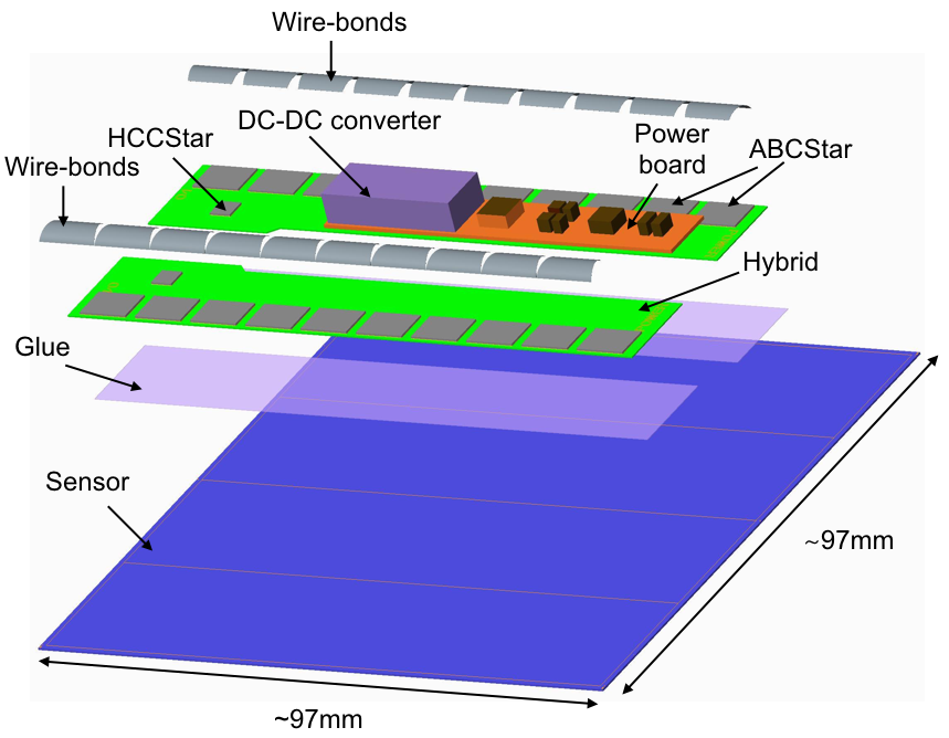
Each module contains two different ASICs used in the readout of data. ATLAS Binary Chips (ABCStars) digitize hits from the silicon strip sensors and cluster the data. A hybrid contains a group of 6 to 11 ABCStars and a Hybrid Controller Chip (HCCStar), which receives trigger commands and dispatches them to each attached ABCStar. These ASICs form a star network, hence their names, as the HCCStar receives clusters back from the ABCStars in parallel. These asynchronous streams need to be combined into data packets and then transmitted out of the detector.
The HCCStar also supports a multi-level triggering mode. In this mode, track information from up to 10% of the detector would be used to make the Level 1 (L1) triggering decision. The HCCStar thus has to support two types of readout commands: regional readout requests (R3s), which will have higher priority than the normal command, a L1 trigger.
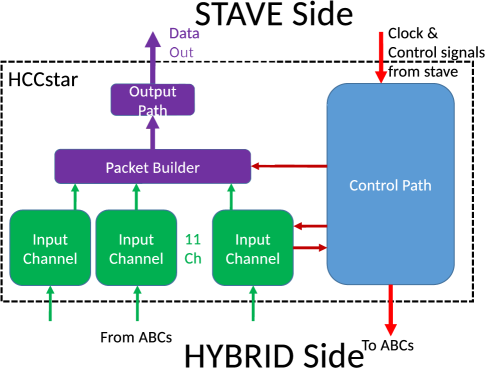
A high-level logic diagram of the HCCStar is shown in Figure 2. To support all these features, a large amount of digital logic is required. The HCCStar’s digital components were written in the hardware description languages Verilog and VHDL. The codebase for the HCCStar engineering prototype consisted of over 12,000 lines of Verilog and nearly 5,000 lines of VHDL. Fabricating these ASICs costs about , which makes it critical to simulate and verify the designs before submitting them for production.
3 Digital Logic Verification
Digital verification is typically done by writing a simulation framework (known as a “testbench”) using one of two approaches:
-
•
Write a testbench by hand in a hardware description language. This is ideal for simple designs and is relatively straightforward, but it is difficult to scale up to complex designs.
-
•
Use a verification library as the starting point for the testbench. Frameworks like the Universal Verification Methodology (UVM) [5], an industry-standard approach to digital logic verification, enable very powerful testbenches to be created.
For the HCCStar, the first approach was rejected due to the large amount of digital logic that required verification. The second approach was considered, but ultimately rejected as well due to the high complexity and learning curve of UVM.
Instead, the HCCStar verification was done using the open-source package cocotb [4] (“coroutine cosimulation testbench”). Cocotb makes it possible to write the testbench code in the Python programming language, thus separating the problems of hardware design (which is still done using a hardware description language) and hardware simulation (which can now be done using a general-purpose programming language).

Figure 3 shows the rough architecture of a cocotb testbench. Communication between the Verilog/VHDL simulator (where the digital design is running) and the Python test code is mediated by the cocotb library. When Python code is executing, the simulator is paused: the testbench must explicitly yield control back to the simulator to allow any changes to digital signals to propagate. The testbench can then wait for a triggering event before resuming control, such as a certain amount of simulation time passing or the toggling of a signal. This approach is known as cosimulation.
To verify the HCCStar’s digital logic, Python driver and monitor classes were created to control inputs and receive outputs using this approach. A Python model of the ABCStar was written that would respond to readout commands and produce properly-formatted data packets. Tests were written to validate all features and probe edge cases. Code coverage tools in the Cadence simulator were used to ensure all major features were probed by the tests.
One important subset of these tests involved checking the radiation tolerance of the digital logic, by simulating single-event upsets (where ionizing radiation causes a flip-flop to toggle) inside the design. The cosimulation approach made it easy for Python tests to change the state of a flip-flop, then yield control to the simulator and check to see if any behavioral problems develop. These tests were particularly important due to the high dosage of radiation the ASICs will be exposed to over the lifetime of the HL-LHC.
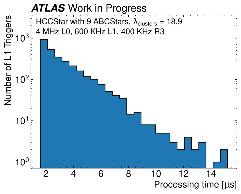
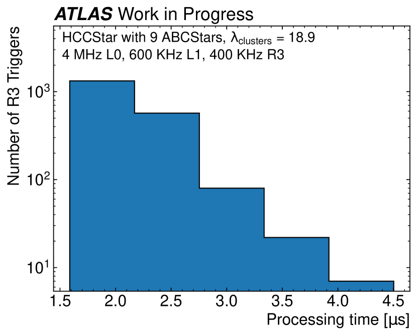
The same testbench was also used to run combined simulations of both the HCCStar and ABCStar designs. The Python ABCStar model was replaced with the real ABCStar codebase and simulations of a full hybrid ran under realistic operating conditions. Not only did this allow the interface between the two chips to be verified, but it also enabled long, realistic simulations of data-flow to be conducted. The use of Python made it possible to use various scientific computing packages (PyROOT, numpy, matplotlib, etc.) from inside the testbench, to produce monitoring plots and perform studies to check the expected performance of the design. Figure 4 shows example monitoring plots in which the response time was measured for a “worst case” hit occupancy and readout rate.
4 Conclusion
The cocotb approach to digital logic verification was found to be extremely powerful for the development of an ASIC like the HCCStar. The use of Python made it easy for graduate students and postdocs to contribute to the verification effort and assist the full-time engineers responsible for the digital logic design.
During the development of the first engineering prototype, over 65 issues of varying severity were found and fixed, highlighting the importance of thorough testing before submission. As of this writing, the engineering prototypes have been fabricated and are undergoing physical testing. While some revisions for the final design are planned, the prototypes have mostly performed as expected, indicating that the HCCStar verification using cocotb was a success.
References
- [1] ATLAS Collaboration “The ATLAS Experiment at the CERN Large Hadron Collider” In JINST 3, 2008, pp. S08003 DOI: 10.1088/1748-0221/3/08/S08003
- [2] ATLAS Collaboration “Technical Design Report for the ATLAS Inner Tracker Pixel Detector”, 2017 URL: https://cds.cern.ch/record/2285585
- [3] ATLAS Collaboration “Technical Design Report for the ATLAS Inner Tracker Strip Detector”, 2017 URL: https://cds.cern.ch/record/2257755
- [4] Chris Higgs and Stuart Hodgeson “cocotb” URL: https://github.com/cocotb/cocotb
- [5] “IEEE Standard for Universal Verification Methodology Language Reference Manual” In IEEE Std 1800.2-2017, 2017, pp. 1–472 DOI: 10.1109/IEEESTD.2017.7932212
- [6] Benjamin John Rosser “Cocotb: a Python-based digital logic verification framework” CERN, 2018 URL: https://indico.cern.ch/event/776422/