Progress Towards Ramsey Hyperfine Spectroscopy in ASACUSA
Abstract
This proceedings contribution reports on progress on the design of a Ramsey-type spectrometer that will be used for the spectroscopy of the ground-state hyperfine structure of both hydrogen and deuterium.
1 Antihydrogen spectroscopy program of ASACUSA
The ASACUSA-CUSP (Atomic Spectroscopy And Collisions Using Slow Antiprotons) antihydrogen experiment based at the Antiproton Decelerator facility of CERN aims to perform precise tests of CPT symmetry by measuring the ground-state hyperfine structure (GS-HFS) of antihydrogen atoms and comparing it with that of hydrogen.[1] A brief account on the status of ASACUSA’s antihydrogen program can be found within these proceedings.[2] The currently applied Rabi-type beam-spectroscopy method can be made more precise by the implementation of Ramsey’s technique of using two separated oscillatory fields.[3] This improvement will first be tested on hydrogen and later on deuterium, which can help constrain the associated SME coefficients.[4]
2 Design of the spectrometer and its scope
An in-beam spectroscopy method comprises a spin-selected atomic beam, an oscillating field to drive transitions between two different spin states, a field gradient to select spin states of interest, and a detection scheme to measure the amount of beam in this state.
In this section we report the progress on a new broadband microwave-generation system that is well suited for in-beam spectroscopy using the Ramsey method. Simulations for a stripline traveling-wave device have been studied with COMSOL 5.3 using the 2D electrostatic study feature in the AC/DC Module.[5] A cross-sectional view of the device consisting of two electrodes and housed inside a mm diameter cylinder is shown in Fig. 2.
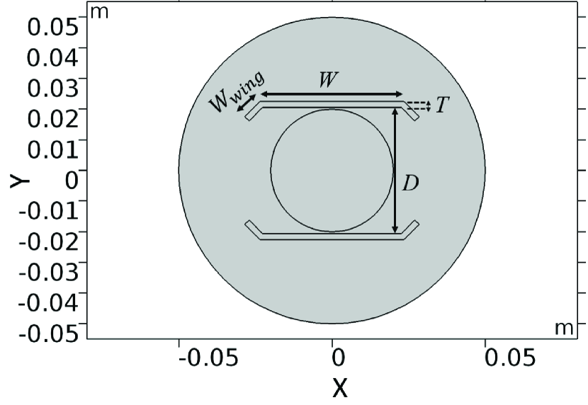
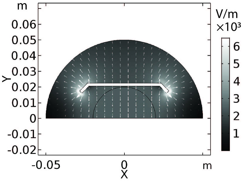
The mm diameter circle in between the two electrodes represents the area where the hydrogen beam will be present. The electrostatic problem was solved for only half the structure and using the central plane between the two electrodes as a virtual ground. The potential at the electrode boundaries was V while the remaining boundaries were all defined as ground. The resulting electric field is shown in Fig. 2. The electric field is perpendicular to the electrode, hence when operated in transverse electromagnetic (TEM) mode, the oscillating magnetic field () will be parallel to the electrode and perpendicular to the axis of the cylindrical housing. The impedance of the structure was calculated as , where is the speed of light in free space and is the computed capacitance. The electric-field inhomogeneity (ratio of the standard deviation to the average of the norm of the electric field) of the structure was studied in the area where the hydrogen beam would be present. The geometrical configuration with mm, mm, mm, and mm has an impedance of , and electric-field inhomogeneity.
The and transitions[2] require different orientations of relative to an external static magnetic field ().[2] This means that with the stripline structure and an axial magnetic field along the beam direction, we can only measure the transition. To measure the transition, a TE110 mode cavity can be used, which has along its axis. As the transition in hydrogen is insensitive to Lorentz violation,[4] it can be used as a benchmark against the transitions.
Due to the broadband nature of the TEM travelling waveguide we can measure the GS-HFS of deuterium around MHz, in addition to that of hydrogen at GHz. The energy shifts of the hyperfine Zeeman levels in deuterium due to the effects of CPT and Lorentz violation within the Standard-Model Extension framework are shown in Eq. (123) of Ref. \refciteSMEpaper, and they depend on the expectation values the momentum of the proton relative to the center of mass of the deuteron () and its higher powers ().[4] This feature, being significantly different from that of hydrogen, leads to the enhancement of the sensitivity to coefficients for Lorentz and CPT violation[4] by a factor of for coefficients with and for coefficients with .
3 Summary and outlook
We have reported on the geometry of a stripline structure that can be used as an interaction zone in Ramsey-type spectroscopy for GS-HFS measurements of hydrogen and deuterium. The advantages of using two different microwave regions for the and transitions have also been discussed.
Next, the transition from RF feedthroughs to the striplines for feeding microwaves into the device will be designed with input from further simulations. Later, possibilities for measuring transitions in deuterium will be studied with simulations of split ring resonators[6] instead of a TE110 cavity.
Acknowledgments
This project is supported by the European Union’s Horizon 2020 research and innovation program under the Marie Skłodowska-Curie grant agreement No. 721559 and the Austrian Science Fund FWF, Doctoral Program No. W1252-N27. We also acknowledge Dr. Fritz Caspers for helping us with the design of microwave devices.
References
- [1] E. Widmann et al., Hyperfine Interact. 240, 5 (2019).
- [2] M.C. Simon, these proceedings (also: arXiv:1910.03959).
- [3] N.F. Ramsey et al., Rev. Mod. Phys. 62, 541 (1990).
- [4] V.A. Kostelecký et al., Phys. Rev. D 92, 056002 (2015).
- [5] AC/DC Module User’s Guide, Version 5.3, COMSOL, Inc., www.comsol.com.
- [6] W.N. Hardy et al., Rev. Sci. Instrum. 52, 213 (1981).