Scalability of TTool’s AMS extensions: a case study
Abstract
Embedded cyber-physical systems (CPS) are commonly built upon heterogeneous digital and analog integrated circuits, including sensors and actuators. Less common is their deployment on parallel, NoC based designs based on general purpose processor cores of a Multi-processor System-on-chip (MPSoC). Application code has to be run on the MPSoC for the digital part, and interact with the analog sensors. We recently proposed a major extension to the design and exploration tool named TTool, now allowing the design of CPS on a high level of abstraction and the generation of cycle-bit accurate simulations. We explore the scalability of our approach with an automotive case study.
I Introduction
Many applications e.g. from robotics, automotive and autonomous systems require heterogeneous modeling - including modeling of analog/mixed signal (AMS) and radio frequency (RF) features. In very early design phases, rapid but less precise exploration of the design space is required. Co-simulation of heterogeneous embedded systems then requires a high-level representation that includes high-level models of AMS and RF components. In the approach we presented in [9] software is run on the digital multiprocessor system on chip (MPSoC) platform, but has to communicate with the analog part. Whereas that work took as a starting point an analog application where only the controller was defined as a task running on a SoC, [13] presented a full methodology on a toy example. The present paper explores a far more complex case study, where a lot more functionality resides in the software tasks.
The next section presents the ways in which the design problems problems are addressed in similar research work. Section III presents the bases. Some of the questions raised when modeling larger applications are listed in Section IV; Section V illustrates them by a larger case study, Section VI concludes the paper.
II Related Work
Well established tools in analog/mixed signal design, like Ptolemy II, [18] [22], based upon a data-flow model, address heterogeneous systems by defining several sub domains using hierarchical models. Instantiation of elements controlling the time synchronization between domains is left to the responsibility of designers.
Metropolis [4] is based on a high level model and facilitates the separation of computation from communication concerns. Metro II [10] introduces hierarchy and allows Adaptors for data synchronization as a bridge between the semantics of components belonging to different MoCs; the model designer still has to implement time synchronization. As a common simulation kernel handles all process execution, MoCs are not well separated.
Discrete Event System Specification (DEVS [7]), a modular and hierarchical formalism for modeling and analyzing general systems that can be discrete event or continuous state systems.
SystemC [16] is a C++ class library which makes it possible to model (digital) hardware on multiple levels of abstraction. Among the frameworks based on SystemC are HetSC [15], HetMoC [26] and ForSyDe [20], all having the disadvantage that instantiation of elements and controlling the synchronization have to be managed by the designer.
SystemC-AMS extensions [1] is a standard describing an extension of SystemC with AMS and RF features [24]. The usual approach for modeling the digital part of a heterogeneous system with SystemC is to rely on the Discrete Event (DE) part of SystemC AMS extensions. The Timed data Flow (TDF) part adds support for signals where data values are sampled with a constant time step.
In the scope of the project BeyondDreams [5], a mixed analog-digital systems proof-of-concept simulator has been developed, based on the SystemC AMS extension standard. Another simulator is proposed in the H-Inception project [14]. All of these approaches rely on SystemC AMS code i.e. they don’t provide a high-level interface for specifying the application. Integration with software code for general-purpose CPUs and with an operating system is however not yet addressed in these approaches.
III Context
III-A TTool
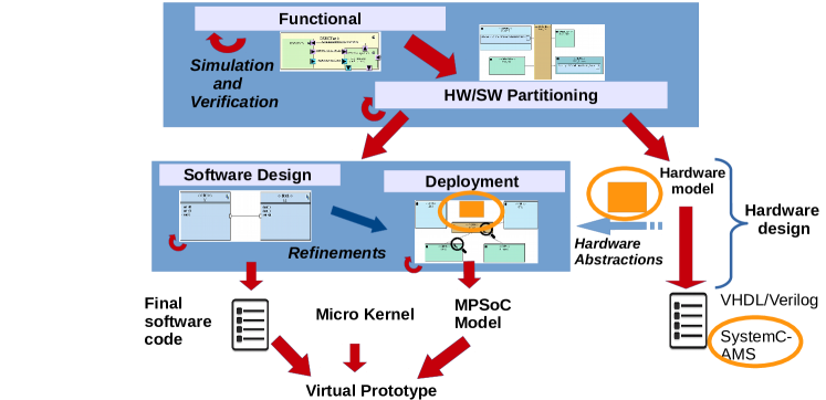
Our modeling framework is the free and open-source software called TTool [3]. TTool relies on SysML to propose two abstract modeling levels: (i) HW/SW partitioning and (ii) software design and deployment [21]. Software tasks for the partitioning model are captured within the functional abstraction level, and software tasks used in deployments are captured in the software design abstraction level. In both levels, the computation part of tasks is then deployed to processors and hardware accelerators, and the communication and storage parts are deployed to buses and memories. In the software deployment level, so-called deployment diagrams are used to capture the allocation of software components onto a MPSoc platform. The tool chain which generates a cycle/bit accurate MPSoC virtual prototype built from SoCLib [23] components is explained in [12]. Figure 1, stemming from [13], shows the overall design flow.
TTool was recently extended with support for modeling CPS [13], and validated for smaller examples but not yet whether the methodology scales to larger case studies.
III-B SystemC Extensions for AMS
SystemC [16] relies on a Discrete Event (DE) simulation kernel. Timed Data Flow (TDF) is one of the (main) MoC of SystemC-AMS. It adds to SystemC support for signals where continuous data values are sampled with a constant time step. A TDF module is described by an attribute representing a time step and a so-called processing function. The time step is associated to a time period during which the processing function should be executed. The processing function corresponds to a mathematical function depending on both inputs and internal states. TDF modules interact with discrete parts using converter ports and have the following attributes:
-
1.
Module Timestep (Tm) denotes the period during which the module is activated. A module will be activated only if there are enough samples available at its input ports.
-
2.
Rate (R). Each module will read or write a fixed number of data samples each time it is activated, annotated to the port as port rate.
-
3.
Port Timestep (Tp) denotes the period during which each port of a module will be activated. It also denotes the time interval between two samples being read or written.
-
4.
Delay (D). A delay can be assigned to a port and will make the port handle a fixed number of samples at each activation, and read or write them in the following activation of the port.
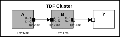
Figure 2 shows a cluster, where the DE modules are represented as white blocks, TDF modules as gray blocks, TDF normal ports as black squares, TDF converter ports as black and white squares, DE ports as white squares and TDF signals as arrows.
III-C MPSoC Virtual Prototype
In case software code is also deployed, an MPSoc platform containing processors / buses / memories must also be generated, as well as a description of mapping of tasks and other software objects provided. SoCLib offers a way to describe Multi-Processor System-on-Chip platforms with semantics based on the shared memory paradigm. Components can be initiators issuing requests (typically CPUs and hardware accelerators), or targets answering to requests (e.g. RAM).
In order to combine SoCLib specification with SystemC-AMS components, we have defined generic adaptor modules that can connect SystemC-AMS components to Virtual Component Interface (VCI) [25] interfaces. The main idea for the integration of SystemC-AMS and SoCLib components into TTool is that analog components act as targets for the SoCLib initiator digital components (CPUs, DMA, …).
An adapter is modeled as a general-purpose input/output (GPIO) target component, following the modeling rules for writing cycle-bit precise SystemC simulation models for SoCLib described below. GPIO components are visible in the deployment diagram, and, like the other VCI components, their interconnection to the central VCI interconnect is represented by an arc. The generated top cell is thus composed of SoCLib modules and interfaces to the SystemC-AMS clusters.
III-D Simulation
Due to their different Model of Computation, AMS components require to execute their simulated behavior apart from the rest of the system, but regularly synchronize with the digital platform. The SystemC kernel is thus controlling the AMS kernel which runs continuously until it is interrupted by access to a converter port by a TDF cluster. Since model-driven approaches expect to ideally provide model validation before code generation (and thus simulation), we propose a way to statically identify synchronization problems [8].
IV Questions raised
Until now, applications modeled with the recent extension of TTool ran basically on mono processors, even if, as mentioned in [9], SoCLib is designed for MPSoC virtual prototypes.
But does this also hold for multiple sensors connected by multiple GPIO and for a MPSoC with multiple processors? The rover application in [13] contained only two sensors, each came with its GPIO with one input and one output port, and a single processor. Larger applications feature several GPIO, more ports, each accessing the central interconnect as a target, generating additional traffic.
Secondly, in the presence of multiple TDF clusters, addressed by different parts of the software running on the SoCLib MPSoC, read and write operations between the digital and analog part must be handled carefully. Not only must causality between TDF and DE be respected as shown in [9, 2], also the semantics of accesses by several analog blocks to the same digital block and vice versa must be preserved. Thirdly, the GPIO interface is to date limited to transmitting only one value at a time, of a basic type. In SystemC-AMS, it is quite complicated to pass structured data types as parameters of a module. While TTool already handles them issue when generating pure SystemC-AMS code, GPIO interfaces do not yet take them into account.
V Case Study
These problems and current attempts at their solution are illustrated by an automotive embedded system designed in the scope of a past European project [11] and the code generation for which was presented in [19].
Recent on-board Intelligent Transport (IT) architectures comprise a very heterogeneous landscape of communication network technologies (e.g., LIN, CAN, MOST, and FlexRay) that interconnect in-car Electronic Control Units (ECUs).
One of these is automatic braking [17], which works essentially as follows: an obstacle is detected by another automotive system which broadcasts that information to neighboring cars. A car receiving that information has to decide whether or not it is concerned. This decision includes a plausibility check function that takes into account various parameters, such as the direction and speed of the car, and also information previously received from neighboring cars. Once the decision to brake has been taken, the braking order is forwarded to relevant ECUs. Also, the presence of this obstacle is forwarded to other neighboring cars in case they have not yet received this information.
The functional view comprises of a set of communicating tasks whose is described abstractly. Mapping then partitions the application into software and hardware. A task mapped onto a processor will be implemented in software, and a task mapped onto a hardware accelerator is implemented in hardware. Tasks destined to be implemented in hardware are either digital or analog; each task is represented on a separate panel. In the example, all sensors obtaining information from the environment will be modeled as analog blocks.
V-A Software design
Once the partitioning is done, the user designs the software, for which functional simulation and formal verification are performed. Figure 3 shows the block diagram from [19] with on top the five sensors, modeled as software tasks. In the current version, the five sensors in the TestBench block are no longer modeled as software tasks. Remaining software components are grouped according to their destination ECU:
-
•
Communication ECU manages communication with neighboring vehicles.
-
•
Chassis Safety Controller ECU (CSCU) processes emergency messages and sends orders to brake to ECUs.
-
•
Braking Controller ECU (BCU) contains two blocks: DangerAvoidanceStrategy determines how to efficiently and safely reduce the vehicle speed, or brake if necessary.
-
•
Power Train Controller ECU (PTC) enforces the engine torque modification request.
To prototype the software components with the other elements of the destination platform (hardware components, operating system), we must map them to a model of the target system. Mapping can be performed using the deployment features introduced in [12]: such a deployment diagram is a SysML representation of hardware components, their interconnection, tasks and channels.
V-B Modeling sensors
Modeling the sensors by blocks of code translated to Posix tasks running on the MPSoC, as was practice beforehand, oversimplified the problem. All five sensors are thus replaced by more realistic analog models: five independent TDF clusters (keeping in mind that TDF still is a strong abstraction of analog behavior).
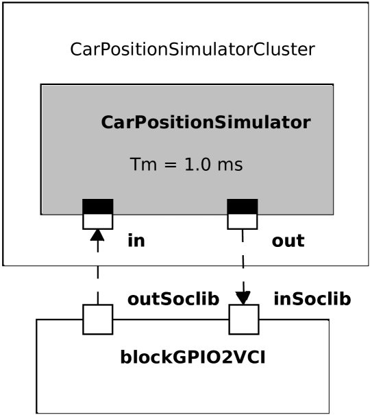
Figure 4 shows an AMS panel with one of the sensor clusters, the CarPositionSimulator sensor. In further dialogues, not shown here, parameters like rate and delay can be entered. From these graphical information, TTool then infers, if possible, missing parameters, calculates a coherent schedule and generates SystemC-AMS code, comprising the ports, delays and interfaces [8]. This cluster is read by the DSRSC_Management block and gives information on the car id and position. Often, data structures or more than one parameter are transmitted in the channels (here, id and position). Currently, they have to be transmitted one by one, basic type by basic type. Thus, id and position require two sequential write operations to the out port in the processing code and two corresponding read operations in the entry code.
We can easily model the randomized choice of an integer between 1 and 5 (id) and between 3 and 10 (position) stemming from the data type, on the left of Figure 3. The code of this simple processing function is shown on the right of the figure in a separate window. The write primitive sends one integer value to the out converter port.
V-C Communication
A library named libsyscams has been provided to contain read and write primitives on the side of the MPSoC, the read_gpio2vci and write_gpio2vci functions. As shown above, CarPositionSimulator issues two random values from its output port, EmergencySimulator does the same.
On the side of the MPSoC platform, according to TTool’s semantics, the DSRSC_Management block non-deterministically reads from either block, or read a broadcastEmergencyBrakingMessage from a third, the DangerAvoidanceStrategy block. In the current version, the first two blocks being replaced by sensors modeled in SystemC-AMS, this semantics should be preserved.
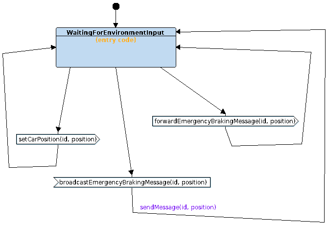
In the following, we give an example of how to use libsyscams to capture non-deterministic read operations. Consider the finite state machine (FSM) of the DSRSC_Management block (Figure 5). In [13], we show how to use entry code that can be contained in a state to call libsyscams. This is the case of the WaitForEnvironmentInput state. Non-deterministically, either the input from CarPositionSimulator or EmergencySimulator is read, whenever values are available on either. This non-determinism, which was in the past expressed by the semantics of TTool’s channels between software blocks, must now be reflected in the entry code of the software block’s state machine. If there are several parameters (here id and position), they must currently be read sequentially.
V-D Deployment
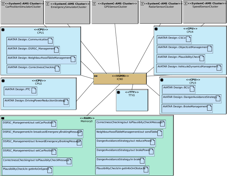
Finally, the extended deployment diagram (Figure 6) gives an overview of the mapping of software tasks and channels. The former are mapped to CPUs, the latter to on-chip memory. For a better overview, the diagram contains sensors as gray boxes, each corresponding to a SystemC-AMS cluster connected via a GPIO. Clicking on the box opens the corresponding SystemC-AMS panel. A fifth CPU which contained the sensors beforehand is no longer in use.
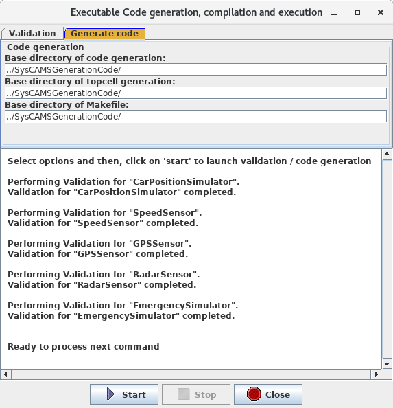
TTool first checks the coherency of the block and port parameters before calculating a valid TDF schedule for each TDF cluster, taking into account synchronization issues between the TDF and DE world [13]. This is done in a so-called validation window (Figure 7). Once the cluster schedule is validated, one can initiate code generation by another mouse click.
The number of targets connected to the central interconnect is now of 17 (five GPIO in addition to the original 12 target modules) and the number of initiators of 4 (one less CPU), potentially stretching the capacity of the VGMN to its limits, to be explored in future experiments.
VI Conclusion and future work
The paper presents a case study which explores current limitations of the AMS extensions of TTool on a larger industrial application. We succeeded in running larger-scale software on a MPSoC; exhaustive exploration and performance evaluation remains to be done.
Communication between the digital and the analog part is performed by C entry code inserted in the state blocks, relaxing the correct-by-construction hypothesis of TTool. Non-determinism of read and write operations should be handled more properly. Also, it should be possible to transmit structured data types and multiple parameters more conveniently.
The TDF models are still oversimplified; in the EVITA industrial case study however, no more detail is available. Next, we will model an application stemming from the Open Source EchOpen project [6], where we will have access to full implementation detail. Finally, even if analog components tend to be unique, we plan to provide a library of parametrizable building blocks for typical components such as filters and analog/digital converters.
References
- [1] Accellera Systems Initiative. SystemC AMS extensions Users Guide, Version 1.0. Accellera Systems Initiative, March 2010.
- [2] L. Andrade, T. Maehne, A. Vachoux, C. Ben Aoun, F. Pêcheux, and M.-M. Louërat. Pre-Simulation Formal Analysis of Synchronization Issues between Discrete Event and Timed Data Flow Models of Computation. In Design, Automation and Test in Europe, Mar. 2015.
- [3] L. Apvrille. TTool, an open-source toolkit for the modeling and verification of embedded systems, 2018.
- [4] F. Balarin, Y. Watanabe, H. Hsieh, L. Lavagno, C. Passerone, and A. L. Sangiovanni-Vincentelli. Metropolis: An integrated electronic system design environment. IEEE Computer, 36(4):45–52, 2003.
- [5] Beyond Dreams Consortium. Beyond Dreams (Design Refinement of Embedded Analogue and Mixed-Signal Systems), 2008-2011. http://projects.eas.iis.fraunhofer.de/beyonddreams.
- [6] E. community. Designing an open-source and low-cost echo-stethoscope. http://www.echopen.org/, 2017.
- [7] A. I. Concepcion and B. P. Zeigler. DEVS formalism: A framework for hierarchical model development. IEEE Trans. on Software Engineering, 14(2):228–241, 1988.
- [8] R. Cortés Porto. Integration of SystemC-AMS simulation platforms into TTool. Master’s thesis, Technische Universität Kaiserslautern, 2018.
- [9] Cortés Porto, Rodrigo, Genius, Daniela, and Apvrille, Ludovic. Modeling and virtual prototyping for embedded systems on mixed-signal multicores. In RAPIDO, 2019.
- [10] A. Davare, D. Densmore, T. Meyerowitz, A. Pinto, A. Sangiovanni-Vincentelli, G. Yang, H. Zeng, and Q. Zhu. A next-generation design framework for platform-based design. In DVCon, volume 152, 2007.
- [11] EVITA. E-safety Vehicle InTrusion protected Applications. http://www.evita-project.org/.
- [12] D. Genius and L. Apvrille. Virtual yet precise prototyping: An automotive case study. In ERTSS’2016, Toulouse, 2016.
- [13] Genius, Daniela, Cortés Porto, Rodrigo, Apvrille, Ludovic, and Pêcheux, François. A tool for high-level modeling of analog/mixed signal embedded systems. In MODELSWARD, 2019.
- [14] H-Inception Consortium. Heterogeneous Inception Project, 2012-2015. https://www-soc.lip6.fr/trac/hinception.
- [15] F. Herrera and E. Villar. A framework for heterogeneous specification and design of electronic embedded systems in SystemC. ACM Transactions on Design Automation of Electronic Systems (TODAES), 12(3):22, 2007.
- [16] IEEE. SystemC. IEEE Standard 1666-2011, 2011.
- [17] E. Kelling, M. Friedewald, T. Leimbach, M. Menzel, P. Sieger, H. Seudié, and B. Weyl. Specification and evaluation of e-security relevant use cases. Technical Report Deliverable D2.1, EVITA Project, 2009.
- [18] E. A. Lee. Disciplined heterogeneous modeling. In D. Petriu, N. Rouquette, and O. Haugen, editors, Proceedings of the ACM/IEEE 13th International Conference on Model Driven Engineering, Languages, and Systems, pages 273–287. Springer LNCS 6395, Oct. 2010.
- [19] L. Li, L. Apvrille, and D. Genius. Virtual prototyping of automotive systems: Towards multi-level design space exploration. In DASIP, 2016.
- [20] S. H. A. Niaki, M. K. Jakobsen, T. Sulonen, and I. Sander. Formal heterogeneous system modeling with systemc. In Specification and Design Languages (FDL), 2012 Forum on, pages 160–167. IEEE, 2012.
- [21] G. Pedroza, D. Knorreck, and L. Apvrille. AVATAR: A SysML environment for the formal verification of safety and security properties. In The 11th IEEE Conference on Distributed Systems and New Technologies (NOTERE’2011), Paris, France, May 2011.
- [22] Ptolemy.org, editor. System Design, Modeling, and Simulation using Ptolemy II. 2014.
- [23] SocLib consortium. The SoCLib project: An integrated system-on-chip modelling and simulation platform. Technical report, CNRS, 2003. www.soclib.fr.
- [24] A. Vachoux, C. Grimm, and K. Einwich. Analog and mixed signal modelling with SystemC-AMS. In ISCAS (3), pages 914–917. IEEE, 2003.
- [25] VSI Alliance. Virtual Component Interface Standard (OCB 2 2.0), Aug. 2000.
- [26] J. Zhu, I. Sander, and A. Jantsch. Hetmoc: Heterogeneous modelling in systemc. In Forum on Specification & Design Languages, pages 1–6. IET, 2010.