figurec
A single-laser alternating-frequency magneto-optical trap
Abstract
In this paper, we present a technique for magneto-optical cooling and trapping of neutral atoms using a single laser. The alternating-frequency magneto-optical trap (AF-MOT) uses an agile light source that sequentially switches between cooling and repumping transition frequencies by tuning the injection current of the laser diode. We report on the experimental demonstration of such a system for 87Rb and 85Rb based on a micro-integrated extended cavity diode laser (ECDL) performing laser frequency jumps of up to with a tuning time in the regime and a repetition rate of up to . For that, a combination of a feed-forward for coarse frequency control and a feedback for precise locking was used. We discuss the results of the AF-MOT characterization in terms of atom numbers and cloud temperature for different operation parameters.
1 Introduction
The development of the magneto-optical trap[1] (MOT) revolutionized the field of cold atom physics, providing a reliable technique for the production of cold and ultracold atomic clouds. Recently, progress has been made in the development of novel miniaturized MOT geometries[2, 3, 4, 5, 6, 7, 8, 9, 10] which may enable the use of cold atom techniques even on challenging experimental platforms that put high demands on size, weight and power consumption such as those in drop towers[11, 12], airplanes [13] and small satellites [14]. For further miniaturization of cold atom experiments, the laser system plays a crucial role as each laser requires driving and control electronics, temperature stabilization and light distribution hardware. Therefore, techniques for reducing the number of lasers are worth exploring. A well-known approach for this involves laser modulation techniques for the generation of sidebands at repumping frequencies such that only a single laser is required[15, 16].
As an alternative approach, we present a novel technique for the operation of a MOT with a single laser that does not require optical modulators: the single-laser alternating-frequency magneto-optical trap (AF-MOT) uses an agile light source that sequentially targets cooling and repumping transitions by tuning the frequency of the laser. This technique is applicable to species with moderate losses to dark states (i.e. long lifetimes in the cooling cycle compared to the timescale of frequency tuning) and is based on previous work performed at Leibniz University Hannover[17].
This paper is structured as follows: Sect. 2 introduces the principle of the AF-MOT. Sect. 3 presents the experimental setup and Sect. 4 explains our technique for the generation of frequency jumps between cooling and repumping transitions with a tuning time in the range. In Sect. 5 we show the results of our AF-MOT experiments with respect to atom number and temperature of the cloud. In Sect. 6 we discuss our results.
2 Principle of the AF-MOT
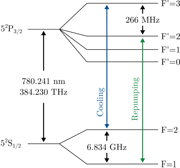
For laser cooling of 87Rb, we use cooling light that is slightly red-detuned from the transition of the line. Without repumping, this results in de-pumping from the bright to the dark ground state and a lifetime in the cooling cycle on the order of . Repumping takes place much faster, on a timescale in the low regime[18]. For the operation of a MOT this means that short repumping pulses with a repetition rate in the regime are sufficient for keeping a large fraction of the atoms in a bright state.
The AF-MOT principle follows from this idea and comprises a single laser that sequentially jumps between cooling and repumping transitions. One cycle of such an AF-MOT sequence
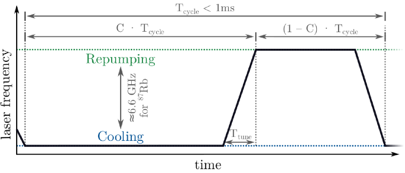
is illustrated in FIG. 1: initially, the laser emits cooling light and thus captures atoms in the trap, while a fraction of the atoms decays into the dark state. Then, a frequency jump is performed that targets the repumping transition, increasing the population of the bright state again. We use to label the fraction of time the laser targets the cooling transition (i.e. the duty cycle of cooling light) including the tuning time of the laser .
For 87Rb, frequency jumps with an amplitude of (see the level scheme in FIG. 2) are necessary to sequentially address the cooling and repumping transitions. These frequency jumps have to be performed at a rate of more than to ensure that a large fraction of the atoms remains in the bright state over multiple cycles. This requirement implies the need for fast frequency jumps, with tuning times in the regime to maximize the time the laser frequency is close to an atomic transition.
3 Experimental setup
For our experiments we use the MOT chamber of the Gravimetric Atom Interferometer GAIN [19]. The trap loads atoms from the background vapor () and is formed by six beams in a 1-1-1 configuration, each with a light power of and an diameter of . Two coils in anti-Helmholtz configuration produce a magnetic field with a central gradient of .
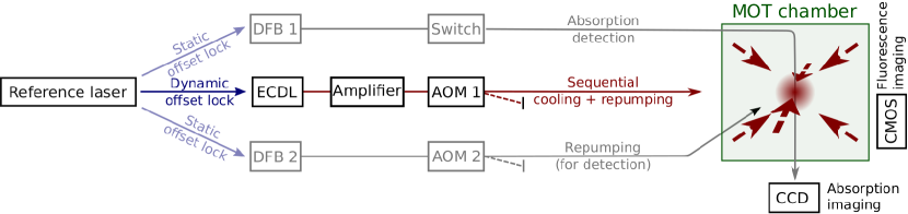
The optical setup for the AF-MOT experiments is sketched in FIG. 3. A micro-integrated extended-cavity diode laser (ECDL) in a master-oscillator power-amplifier design based on the MiLas technology platform [20, 21] served as the light source for our AF-MOT experiments. It delivers light power of up to in-fiber and features a linewidth of (on a timescale of ). For the purpose of an AF-MOT, the single laser was dynamically offset locked (detailed in the next section) to a custom-built reference laser that was itself stabilized to the crossover transition of the 87Rb line by means of frequency modulation spectroscopy[22]. The resulting offset frequencies for cooling light (red-detuned to the transition by ) and resonant repumping light are given by and , respectively (including compensation for a frequency shift of introduced by AOM 1).
For technical reasons, the output of the ECDL was additionally amplified in the distribution module of the GAIN setup. We note that neither AOM 1, nor the two additional distributed feedback lasers (DFBs) are required for the AF-MOT technique itself; they were merely used for repumping the cloud in preparatory experiments as well as for fluorescence and absorption detection.
4 Experimental sequence
First, we prepare the laser system for frequency jumps on a timescale as required for the AF-MOT technique. For that, a feed-forward to the laser’s injection current has to be generated. This task is performed by an iterative algorithm implemented on an FPGA that is described in detail in Sect. 4.1. After several seconds, the algorithm converges and the generated feed-forward is suitable for driving fast frequency jumps. The algorithm continues to run, though, in order to compensate for laser drifts and to adapt the feed-forward signal to changing environmental conditions.
When we send the amplified laser light to the vacuum chamber, the MOT loading starts. When a steady-state is reached after a loading time of several seconds, we examine the atomic cloud by performing fluorescence and absorption measurements in order to determine the atom number and cloud temperature (Sect. 4.2).
4.1 Generation of laser frequency jumps with a microsecond tuning time
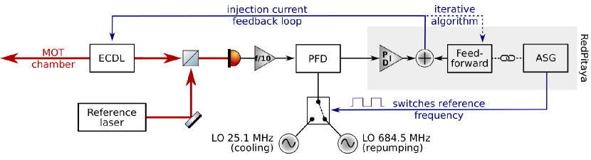
For a 87Rb AF-MOT, frequency jumps of with -accuracy have to be performed on a timescale. In order to simultaneously fulfill both requirements — agility and precision — we chose a combined approach of a feed-forward, for coarse frequency control, and a feedback (PID), for precise locking. The setup used for this dynamic offset lock is depicted in FIG. 4.
The optical phase-locked loop (OPLL) consists of a radio frequency (RF) prescaler (RF Bay FPS-10-12) and a phase-frequency detector (PFD, OnSemiconductor MC100EP140) that compares the beat-note between ECDL and reference laser with an alternating RF reference frequency derived from two local oscillators (LO); the PID servo filter is implemented on the FPGA of a RedPitaya STEMlab device. Its output controls the injection current of the ECDL’s master oscillator (MO) via the modulation port of the current driver (ILX Lightwave 3724 in high-bandwidth mode). In order to switch between two different target frequencies of the offset lock (i.e. cooling and repumping frequencies), an RF switch (composed of two MiniCircuits ZASWA-2-50DR+ and a ZFSC-4-1-S+ combiner) is triggered repetitively using the arbitrary sequence generator (ASG) of the RedPitaya.
As mentioned above, we found that we had to combine the OPLL’s feedback signal to the laser injection current with a feed-forward in order to achieve fast frequency jumps. The naive approach of using a simple step function for this purpose is bound to fail, though, as the ECDL exhibits a complex frequency response to changes in the current on these short time scales. While to our knowledge no analysis of such fast frequency tuning of ECDLs exists, a study of the behavior of DFBs on very short timescales is published in Ref. 23. These two laser designs are similar in that a step in the injection current influences the laser frequency in the same two ways[24]: first, it alters the refractive index of the laser medium which happens almost instantaneously; secondly, thermal effects continue to shift the frequency.
We solved the problem by generating a non-trivial feed-forward that accounts for the complex frequency response of the laser. For the preparation of this signal we use an iterative algorithm that is fully implemented on the FPGA using Migen[25]: to begin with, a sequence of alternating LO frequencies is initialized, with repetition rate and duty cycle corresponding to the desired values of and . The PID then aims to drive the laser between these two target frequencies. In each step of the iterative algorithm, the output of the PFD (containing information on when the laser frequency is lower or higher than the target frequency) is analyzed over one cycle: for each point in time, the average detuning at later times is calculated. This information is used to modify the feed-forward for the next step. Futhermore, several filters are applied to this signal in order to suppress oscillations. As each iteration takes less than , the algorithm converges within several seconds and the required frequency jumps can be performed within approximately with moderate overshooting and ringing, fulfilling the requirements for an 87Rb AF-MOT.
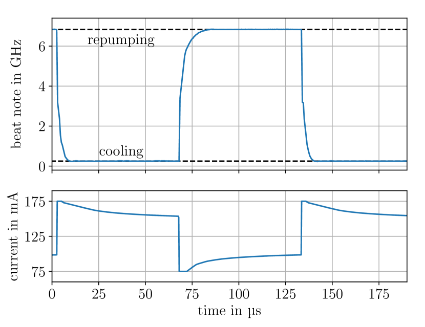
An exemplary cycle of the AF-MOT sequence is depicted in FIG. 5. The figure shows that the algorithm generates instantaneous current steps as large as to perform the frequency jumps of , although only roughly are expected from the ECDL’s slow tuning coefficient (approximately ). This discrepancy is due to the aforementioned complex frequency response of the laser. This is indicated in the graph, showing that subsequent to a frequency jump the feed-forward signal compensates for frequency drifts caused by temperature changes inside the laser.
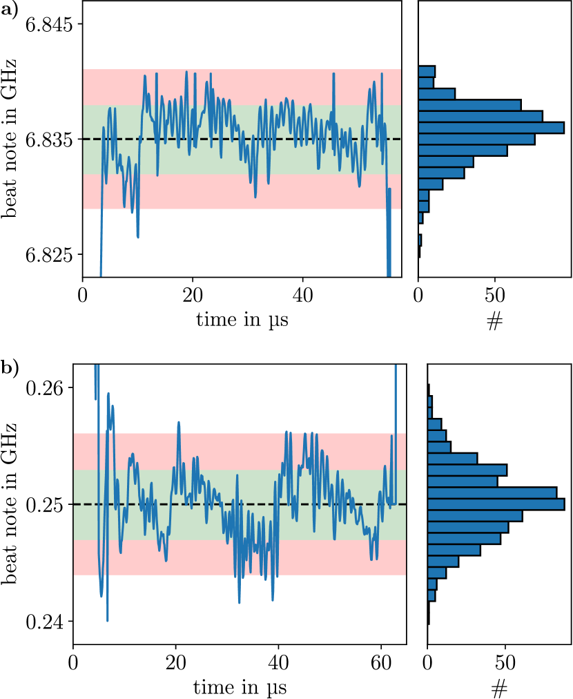
FIG. 6 shows a zoom of the frequency jump cycle, highlighting the accuracy of the frequency tuning. In this plot, % of the data points are within around the target frequency, with being the linewidth of the 87Rb line; considering the whole cycle, including times of frequency tuning, this holds % of the time.
The algorithm runs continuously during our experiments to compensate for laser drifts and to adapt the feed-forward signal to changing environmental conditions. It is worth noting that the AF-MOT cycles for 87Rb were observed to run reliably for several hours without mode hops, despite the jump amplitude () being on the order of magnitude of the mode-hop-free tuning range of the ECDL ().
We want to note that the method presented above is not specifically tailored for our ECDL and that it should be applicable to other laser sources such as commercially available macroscopic ECDLs, DFB or DBR laser sources as well. The major requirements are fast tunability between the required optical frequencies and a low frequency drift that may be compensated for by the slowly adapting feed-forward. The use of a DFB or DBR laser as main light source may be advantageous as these laser designs typically exhibit a large mode-hop free tuning range and a higher tuning coefficient compared to ECDLs[24] that may allow for even faster frequency jumps. Additionally, it means that smaller injection current changes are sufficient for driving the AF-MOT sequence. Given that temperature changes cause mechanical stress, this may mitigate potential lifetime issues of the laser.
4.2 Measurement of atom number and cloud temperature
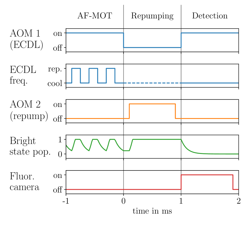
We use fluorescence imaging in order to determine the atom number of the MOT. Images taken during the AF-MOT sequence are not useful for these purposes, though, as the population of bright states varies over which we can not resolve given the minimum exposure time of our cameras. Instead, we implemented a procedure for repumping the cloud before taking an image of the fully repumped ensemble. The timing of this procedure is illustrated in FIG. 7. After loading the MOT, the ECDL’s output is blocked by AOM 1 and a dedicated repumping laser (DFB 2) is turned on using AOM 2, pumping all atoms to the bright state.
For fluorescence imaging, we then excite the atoms with cooling light and trigger the camera (The Imaging Source DMM 22BUC03-ML). In this way we record a fluorescence signal that is proportional to the number of atoms inside the cloud because the camera’s exposure time of is much longer than the time constant of decay to the dark state.
Additionally, we determine the temperature of the cloud by performing time-of-flight measurements using absorption imaging of the freely expanding atomic cloud. For that purpose, we switch off the magnetic field immediately after the the last AF-MOT cycle and block all laser light. We determine the optical density of the repumped cloud by absorption imaging (using a PCO Imaging Pixelfly 270 XS camera). To this end, an imaging beam (emitted by DFB 1) with a power of and an diameter of is switched on by an optical switch (Agiltron NanoSpeed) and the camera is triggered with an exposure time of .
5 Results
5.1 Atom numbers for 87Rb
In general, the number of atoms that can be trapped using the AF-MOT technique is lower than that of an equivalent cw-MOT because the atoms are not continuously subjected to light forces. This results in a reduction of the capture velocity such that atoms from the high velocity tail of the temperature distribution cannot be trapped.
It is useful to characterize the AF-MOT atom number in terms of the atom number achieved in an equivalent steady-state cw-MOT (which is toms after in our set-up). We record this relative atom number as a percentage for a range of different switching cycles by varying the repetition rate and duty cycle . For an immediate comparison we sequentially load a conventional cw-MOT and an AF-MOT for each data point to reject potential variations of the atom number on longer timescales.
5.1.1 AOM-switched dual-laser AF-MOT
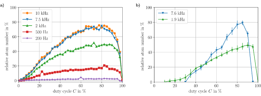
In order to get an estimate for the maximum achievable performance of an ideal AF-MOT (i.e. an AF-MOT without degradation due to finite tuning time and overshoot), we used a conventional cw-MOT system and emulated an AF-MOT by alternately switching the cooling and repumping lasers using AOMs. The result is shown in FIG. 8a. As the AOM switching time is in the regime, only repetition rates of up to were considered. We want to mention that this system is not perfectly equivalent to an actual single-laser AF-MOT as repumping is performed using an additional laser beam (DFB 2) with lower power from an extra port of the vacuum chamber, whereas the AF-MOT is repumped by the ECDL with strong pulses from all six MOT beams.
In agreement with our expectations, AF-MOT repetition rates in the range (i.e. cycle times of less than ) are required to reach atom numbers that are close to those of a conventional cw-MOT. In this regime, faster repetition rates are advantageous as they lead to a higher bright state population and thus increase the average time an atom is subjected to light forces. Assuming perfect frequency tuning (i.e. no dead time between the different laser frequencies as well as no overshooting), relative atom numbers of are achievable with the AF-MOT technique for 87Rb and repetition rates of up to .
5.1.2 Single-laser AF-MOT
Having determined promising repetition rates and duty cycles by means of the AOM-switched dual-laser test system, we investigated the actual single-laser AF-MOT. Using the technique for dynamic offset locks described in Sect. 4.1, continuous laser frequency jumps between cooling and repumping transitions of 87Rb were generated for different duty cycles with a repetition rate of (corresponding to a fraction of the FPGA’s clock frequency). The resulting atom numbers are shown in FIG. 8b. It should be noted that due to technical issues these experiments were conducted with a reduced laser light power, corresponding to roughly of the power used in the previous section for the AOM-switched dual-laser AF-MOT.
We find that the relative atom numbers of the single-laser AF-MOT roughly match the ones of the AOM-switched dual-laser AF-MOT. The main discrepancy is given by a reduced number of atoms for small and large duty cycles which we attribute to two effects: first, the finite laser frequency tuning time of the single-laser AF-MOT corresponds to a dead time of during which the light may not excite atomic transitions, whereas cooling and repumping frequencies are alternated without delay in case of the AOM-switched AF-MOT. Second, the relative impact of overshooting and ringing (apparent in FIG. 6) on the effective duty cycle or of the cooling and the repumping part, respectively, becomes more significant for shorter duty cycles.
Despite this difference at the edges of the plot, the maximum relative atom number achieved is roughly the same: the largest AF-MOT atom number was observed to be approximately for a duty cycle of . With respect to a conventional cw-MOT we found a relative atom number of approximately that is reached with about the same loading time as our cw-MOT.
5.2 Atom numbers for 85Rb
As a proof of principle, the AF-MOT technique was also demonstrated using 85Rb. In this case, frequency jumps of were required, corresponding to the difference between cooling ( ) and repumping ( ) transitions of the 85Rb line. This allows for faster frequency tuning times compared to 87Rb whose ground state splitting is roughly twice as large. On the other hand, the lighter isotope exhibits a smaller line splitting which leads to faster decay to the dark state. Experimentally, a relative atom number of with respect to the case of a conventional dual-laser 85Rb cw-MOT was achieved with a repetition rate of and a duty cycle of .
5.3 Temperature for 87Rb
When performing time-of-flight measurements by means of absorption imaging of a freely expanding cloud, we found no significant differences in temperature between AF-MOT and cw-MOT ().
6 Conclusion and outlook
We have demonstrated a novel technique for single-laser magneto-optical cooling and trapping of neutral atoms and characterized the performance of such an AF-MOT for different operation parameters.
Preparatory experiments were conducted using a conventional MOT system in order to estimate the achievable performance with this technique. In general, the reduced exposure time to cooling light forces leads to lower capture velocities and thus a smaller cloud. Experimentally, we found that for 87Rb the required repetition rate of the cooler-repumper frequency jump sequence is higher than . With an optimized duty cycle, this yields a relative atom number of roughly compared to an equivalent conventional cw-MOT. We point out that the AOM-switched system that was used for these preparatory experiments is not completely equivalent to a single-laser AF-MOT due to a different repumper intensity and a lack of frequency tuning (i.e. no laser light of intermediate frequencies influences the atoms). However, it yields a good estimate for the potential of the AF-MOT technique.
We have implemented a dynamic offset lock, capable of driving laser frequency jumps of (corresponding to the difference between cooling and repumping transitions of 87Rb) with a tuning time of approximately . Finally, we used this technique to demonstrate a single-laser AF-MOT with a maximum atom number of , which is of the equivalent cw-MOT. As this atom number roughly corresponds to the one of the AOM-switched dual-laser AF-MOT, we conclude that our method for the generation of fast frequency jumps works in a satisfactory manner, reaching a tuning precision that has no substantial negative impact on the atom number.
So far, the dynamic offset lock employed by our AF-MOT setup requires a second laser, providing an absolute frequency reference. This means that sophisticated experiments that rely on such a reference for other reasons than cooling and trapping can directly profit from a reduced number of lasers. Additionally, some bare-bone MOT experiments may take advantage of the AF-MOT technique as well. For cooling and trapping of atomic species that exhibit more than a single dark state, an agile laser could sequentially target several repumping frequencies. Moreover, the AF-MOT technique is not limited to the trapping of a single species; due to the similar level structure of 85Rb and 87Rb, even a single-laser dual-species AF-MOT, sequentially addressing 4 different transitions, is conceivable.
Actual single-laser operation (i.e. self-referencing of the AF-MOT laser) may be feasible in future experiments. For that purpose, two different approaches are conceivable. First, a spectroscopy signal could be recorded periodically, either by making use of the fast frequency tuning during the AF-MOT jump sequence or by adding a dedicated ramp to the cycle. Alternatively, a feedback loop based on the fluorescence signal strength alone could be implemented as demonstrated in Ref. 26.
Acknowledgements
We thank Thijs Wendrichs for the detailed review of the manuscript and Victoria Henderson for proof-reading the manuscript and for her helpful comments. We are grateful to Robert Jördens for his advice on FPGA programming.
This work is supported by the German Space Agency (DLR) with funds provided by the Federal Ministry of Economics and Technology (BMWi) under grant numbers DLR50WM1857, DLR50WP1702 and DLR50WP1432.
References
- Raab et al. [1987] E. L. Raab, M. Prentiss, A. Cable, S. Chu, and D. E. Pritchard. Trapping of Neutral Sodium Atoms with Radiation Pressure. Phys. Rev. Lett, 59:2631–2634, 1987.
- Lee et al. [1996] K. I. Lee, J. A. Kim, H. R. Noh, and W. Jhe. Single-beam atom trap in a pyramidal and conical hollow mirror. Opt. Lett., 21:1177–1179, 1996.
- Williamson et al. [1998] R. Williamson, P. Voytas, R. Newell, and T. Walker. A magneto-optical trap loaded from a pyramidal funnel. Opt. Express, 3:111, 1998.
- Vangeleyn et al. [2009] M. Vangeleyn, P. F. Griffin, E. Riis, and A. S. Arnold. Single-laser, one beam, tetrahedral magneto-optical trap. Opt. Express, 17:13601–13608, 2009.
- Bodart et al. [2010] Q. Bodart, S. Merlet, N. Malossi, F. Pereira Dos Santos, P. Bouyer, and A. Landragin. A cold atom pyramidal gravimeter with a single laser beam. Appl. Phys. Lett., 96:134101, 2010.
- Pollock et al. [2011] S. Pollock, J. P. Cotter, A. Laliotis, F. Ramirez-Martinez, and E. A. Hinds. Characteristics of integrated magneto-optical traps for atom chips. New J. Phys., 13:043029, 2011.
- Wu et al. [2017] X. Wu, F. Zi, J. Dudley, R. J. Bilotta, P. Canoza, and H. Müller. Multiaxis atom interferometry with a single-diode laser and a pyramidal magneto-optical trap. Optica, 4:1545, 2017.
- McGilligan et al. [2017] J. P. McGilligan, P. F. Griffin, R. Elvin, S. J. Ingleby, E. Riis, and A. S. Arnold. Grating chips for quantum technologies. Sci. Rep., 7:384, 2017.
- Imhof et al. [2017] E. Imhof, B. K. Stuhl, B. Kasch, B. Kroese, S. E. Olson, and M. B. Squires. Two-dimensional grating magneto-optical trap. Phys. Rev. A, 96:033636, 2017.
- Barker et al. [2018] D. S. Barker, E. B. Norrgard, N. N. Klimov, J. A. Fedchak, J. Scherschligt, and S. Eckel. A single-beam Zeeman slower and magneto-optical trap using a nanofabricated grating. In preparation, 2018.
- Müntinga et al. [2013] H. Müntinga, H. Ahlers, M. Krutzik, A. Wenzlawski, S. Arnold, D. Becker, K. Bongs, H. Dittus, H. Duncker, N. Gaaloul, C. Gherasim, E. Giese, C. Grzeschik, T. W. Hänsch, O. Hellmig, W. Herr, S. Herrmann, E. Kajari, S. Kleinert, C. Lämmerzahl, W. Lewoczko-Adamczyk, J. Malcolm, N. Meyer, R. Nolte, A. Peters, M. Popp, J. Reichel, A. Roura, J. Rudolph, M. Schiemangk, M. Schneider, S. T. Seidel, K. Sengstock, V. Tamma, T. Valenzuela, A. Vogel, R. Walser, T. Wendrich, P. Windpassinger, W. Zeller, T. Van Zoest, W. Ertmer, W. P. Schleich, and E. M. Rasel. Interferometry with Bose-Einstein condensates in microgravity. Phys. Rev. Lett., 110:093602, 2013.
- Rudolph et al. [2011] J. Rudolph, N. Gaaloul, Y. Singh, H. Ahlers, W. Herr, T. A. Schulze, S. T. Seidel, C. Rode, V. Schkolnik, and W. Ertmer. Degenerate Quantum Gases in Microgravity. Microgravity Sci. Technol., 23:287–292, 2011.
- Barrett et al. [2016] B. Barrett, L. Antoni-Micollier, L. Chichet, B. Battelier, T. Lévèque, A. Landragin, and P. Bouyer. Dual matter-wave inertial sensors in weightlessness. Nat. Comm., 7:13786, 2016.
- Oi et al. [2016] D. K. L. Oi, A. Ling, J. A. Grieve, T. Jennewein, A. Dinkelaker, and M. Krutzik. Nanosatellites for quantum science and technology. Contemp. Phys., 58:25, 2016.
- Nellessen et al. [1990] J. Nellessen, J. Werner, and W. Ertmer. Magneto-optical compression of a monoenergetic sodium atomic beam. Opt. Comm., 78:300–308, 1990.
- Chen et al. [1999] C. Chen, Y. Li, K. Bailey, T. O’Connor, L. Young, and Z-T. Lu. Ultrasensitive isotope trace analysis with a magneto-optical trap. Science, 286:1139–1141, 1999.
- Bartosch [2015] W. Bartosch. Development and demonstration of a laser-system with digital frequency control for atom cooling. M.Sc. thesis, 2015.
- Gattobigio et al. [2010] G. L. Gattobigio, T. Pohl, G. Labeyrie, and R. Kaiser. Scaling laws for large magneto-optical traps. Phys. Scr., 81:025301, 2010.
- Hauth et al. [2013] M. Hauth, C. Freier, V. Schkolnik, A. Senger, M. Schmidt, and A. Peters. First gravity measurements using the mobile atom interferometer GAIN. Appl. Phys. B: Lasers Opt., 113:49–55, 2013.
- Wicht et al. [2017] A. Wicht, A. Bawamia, M. Krüger, Ch. Kürbis, M. Schiemangk, R. Smol, A. Peters, and G. Tränkle. Narrow linewidth diode laser modules for quantum optical sensor applications in the field and in space. Proc. SPIE, 10085:10085F, 2017.
- C. Kürbis [2019] C. Kürbis. Extended cavity diode laser master-oscillator-power-amplifier for precision iodine spectroscopy in space. In preparation, 2019.
- Bjorklund et al. [1983] G. C. Bjorklund, M. D. Levenson, W. Lenth, and C. Ortiz. Frequency modulation (FM) spectroscopy. Appl. Phys. B: Photophys. Laser Chem., 32:145–152, 1983.
- Shalom et al. [1998] H. Shalom, A. Zadok, M. Tur, P. J. Legg, W. D. Cornwell, and I. Andonovic. On the various time constants of wavelength changes of a DFB laser under direct modulation. IEEE J. Quantum Electron., 34:1816–1822, 1998.
- Wieman and Hollberg [1991] C. E. Wieman and L. Hollberg. Using diode lasers for atomic physics. Rev. Sci. Inst., 62:1–20, 1991.
- [25] M-Labs. Migen. https://m-labs.hk/migen/.
- Hinton et al. [2017] A. Hinton, M. Perea-Ortiz, J. Winch, J. Briggs, S. Freer, D. Moustoukas, S. Powell-Gill, C. Squire, A. Lamb, C. Rammeloo, B. Stray, G. Voulazeris, L. Zhu, A. Kaushik, Y. H. Lien, A. Niggebaum, A. Rodgers, A. Stabrawa, D. Boddice, S. R. Plant, G. W. Tuckwell, K. Bongs, N. Metje, and M. Holynski. A portable magneto-optical trap with prospects for atom interferometry in civil engineering. Philos. Trans. R. Soc. A, 375:20160238, 2017.