Pathways connecting two opposed bilayers with a fusion pore: A molecularly-informed phase field approach
Abstract
A phase field model with two phase fields, representing the concentration and the head-tail separation of amphiphilic molecules, respectively, has been constructed using an extension of the Ohta-Kawasaki model (Macromolecules 19, 2621-2632 (1986)). It is shown that this molecularly-informed phase field model is capable of producing various self-assembled amphiphilic aggregates, such as bilayers, vesicles and micelles. Furthermore, pathways connecting two opposed bilayers with a fusion pore are obtained by using a combination of the phase field model and the string method. Multiple fusion pathways, including a classical pathway and a leaky pathway, have been obtained depending on the initial separation of the two bilayers. The study shed light to the understanding of membrane fusion pathways and, more importantly, laid a foundation for further investigation of more complex membrane morphologies and transitions.
I Introduction
Membrane fusion is a structural transformation in which two initially separated lipid bilayers merge their hydrophobic cores, resulting in one interconnected structure. The fusion of two opposed lipid bilayers is a fundamental step in many important biological processes ranging from endocytosis and exocytosis, synaptic release, and viral infection to fertilization chernomordik1995lipids ; monck1996fusion ; zimmerberg1999membrane ; jahn2002membrane ; tamm2003membrane ; blumenthal2003membrane . The fusion transformation rate and structure depend sensitively on the transition pathway connecting different intermediate states of the system. Therefore, understanding the structure and energetics of fusion pathways is very important and it has attracted much attention. An intuitively attractive pathway, the so-called classical pathway, connecting two opposed bilayers to a fusion pore was proposed by Kozlov and Markin kozlov1983possible ; markin1983primary . It is assumed that all the morphologies or structures along this pathway are rotationally symmetric. As the first step of the fusion transition, a highly curved intermediate structure, the so-called stalk kozlovsky2002stalk ; kozlovsky2004stalk , is formed by connecting two opposed cis monolayers. In the second step, the displacement of the two inner cis leaves and two outer trans leaves results in the formation of a structure termed hemifusion diaphragmkozlovsky2002lipid ; katsov2004field . Finally, the rupture of this hemifusion diaphragm creates a fusion poremonck1996fusion ; ryham2013teardrop . Besides the classical pathway, other fusion pathways have been proposed. One non-classical pathway is the so-called leaky pathway where a stalk-hole complex configurationkatsov2006field ; muller2003new is formed. Some evidence of the formation of the leaky fusion pathway has been reported in some experimental studies shangguan1996influenza ; bonnafous2000membrane ; dunina2000hemagglutinin ; haque2002influence ; frolov2003membrane , revealing that there is a path connecting the interior of the cells to the outside. Another evidence of the leaky fusion pathways is that mixing of the lipids in the cis leaves and trans leaves has been reported lee1997evolution ; evans2002kinetics .
In the literature, various membrane models have been developed to study the structure of membranes and the process of membrane fusion. Atomistic models are able to provide details of the molecular structure. However, molecular dynamics (MD) simulations of atomistic model of lipid bilayers damodaran1992structure could only extend to systems of the order of a few nm over a time span about 0.1ns. The huge disparity between the capability of MD simulations and the length and time scale of membrane fusion made it virtually impossible to simulate the fusion pathways using atomistic model. In order to overcome this barrier, coarse-grained models, such as the Minimal model carmesin1988bond ; goetz1998computer and the Systematic coarse-graining model yelash2006well , have been introduced. These models reduce the number of degrees of freedom, resulting in a significant computational speed-up at the cost of atomistic details. At an even coarser scale, continuum models, such as the Helfrich elasticity model kozlovsky2002stalk , have been developed for the study of membrane structures and morphologies. It is desirable to develop theoretical models at the mesoscopic scale that could connect the molecular and continuum models.
One possible framework to develop a mesoscopic model for membrane fusion is the phase field model, which is a popular approach for the study of moving interface problems van1979thermodynamic . It is natural to apply this framework to the study of membrane fusion because the membrane could be regarded as a boundary separating the trans and cis sides of the cell.
Within the framework of the phase field model, the physical state of a particular system is described by a continuous phase field which takes different constant values in different phases. The different phases are further connected via smooth interfaces that are in turn determined by certain energy functional of the phase field. Over the years, various phase field models have been developed and applied to a broad-range of problems, such as solidification, solid-state phase transition, coarsening and grain growth, etc kobayashi1993modeling ; li2006temperature ; nestler1999multiphase . The application of phase-field method in study of vesicle membrane is first proposed by Du et al. du2004phase , initially focusing on the shape transformation of single component vesicle. Later applications of phase field model to membranes include the structure of a multi-component vesicle wang2008modelling , a vesicle interacting with a surrounding fluid du2009energetic , and the adhesion of a vesicle to a substrate zhang2009phase . These studies provide interesting understanding of and insight into the morphological change of vesicles. However, in these phase field studies the lipid membranes are treated as a structureless elastic surface. As such, important structural information about the bilayer nature of the membrane is missing in these simple phase field models.
In this paper, we fill this gap by proposing a phase field model that contains molecular information of the amphiphiles. Specifically, we introduce two phase fields, representing the concentration distribution and head-tail separation of the amphiphilic molecules, respectively. The energy (or free energy) functional governing the formation and structure of the bilayers is derived based on the Ohta-Kawasaki model, which is a free energy functional of a specific amphiphilic molecules, i.e., diblock copolymers. The two phase fields describe the macroscopic phase separation between the amphiphiles and solvent and microscopic phase separation between the hydrophilic heads and hydrophobic tails of the amphiphiles, respectively. The energy functional of the proposed phase field model is in the form of a generalized Landau free energy functional containing a number of parameters. The molecular interactions between solvent, amphiphile head and amphiphile tail are encoded in these parameters. Within this molecularly-informed phase field model, the bilayer structure is produced naturally from minimization of the free energy. Therefore, the resulting fusion pathways automatically contain the structural detail of the bilayers. The advantage of this model is its ability to provide a more faithful description of membrane structures and transition pathways, in contrast to the previously proposed simple phase field model with one phase field. As a first step to validate the model, we have obtained numerically the bilayer, liposome and micelle, as equilibria configurations of the model. Furthermore, we also obtained at least four solutions (bilayers, a stalk, a diaphragm and fusion pore) that are solutions of the Euler-Lagrange equation of the free energy functional. These solutions correspond to the intermediate states along the classical fusion pathway. Previous studies of membrane fusion mainly focused on the transition from two apposing bilayers to the stalk smirnova2019thermodynamically ; muller2012transition rather than the entire transition pathway from two opposing bilayers to stalk, from stalk to hemifusion diaphragm and from hemifusion diaphragm to fusion pore. In the current study, we are able to obtain the full fusion pathways using the new phase field model. In what follows, we present two complete membrane fusion pathways. Specifically, when the two opposed bilayers are in close proximity, we find a symmetric classical fusion pathway. However, when the two opposed bilayers are separated by a gap, we find an asymmetric leaky fusion pathway which passes through a stalk-hole complex configuration.
The rest of the paper is organized as follows. In Section II, we present the derivation and explanation of the phase field model in the form of a generalized Landau free energy functional. In Section III, we describe the numerical method used in the current work to compute the free energy minimizers and the transition pathways. In Section IV, we give the main results on the fusion pathways. Finally, Section V contains some concluding remarks.
II Model Development
Bilayer membranes are self-assembled from lipid molecules in water. As such, the development of a phase field model for the study of bilayer membranes must reflects the fact that lipids are amphiphilic molecules composed of a hydrophilic head and hydrophobic tails. As a generic model, we assume that the system is composed of amphiphilic molecules with a hydrophilic head A and hydrophobic tail B and solvents C. If a detailed model of the molecules is given, the property of the system could be studied by using standard tools of statistical mechanics such as mean-field theory and simulations. On the other hand, our purpose is to develop a phase field model containing information about the essential feature of different molecular species. Our derivation of the phase field model is motivated by the work of Ohta and Kawasaki, who have derived a Landau free energy functional of diblock copolymers, which could be regarded as a generic model of amphiphilic molecules. Specifically, we use the functional form of the free energy expansion developed for a system composed of AB diblock copolymers and C homopolymers ohta1995dynamics . Treating the diblock copolymers as an analogue of a lipid molecule and the homopolymers as solvents, we can write down a generic Landau free energy for the system. In the original form of the Ohta-Kawasaki (OK) model ohta1986equilibrium , the parameters of the free energy expansion are derived from the molecular model. In our approach, we will adopt the functional form of the free energy while treat the parameters of the model as phenomenological parameters, as commonly done in the development of phase field models.
Specifically, we assume that the state of the system is described by two independent phase fields or order parameters, and . Here the phase field represents the concentration of the amphiphilies (AB copolymers), thus is an order parameter or phase field describing the macroscopic smacroscopic phase separationeparation of the amphiphiles and the solvents. On the other hand, the phase field represents the difference between the local volume fraction of the head A and tail B, so it describes the microscopic phase separation between the heads and tails. Following the derivation of Ohta and Kawasaki and assuming that our system is incompressible, the free energy of the mixture of amphiphiles and solvents can be written as a sum of short-range and long-range contributions ohta1995dynamics ,
| (1) |
where the short range contribution to the free energy is given by,
| (2) |
where the coefficients and are parameters governing the thickness of macroscopic phase separation interface and microscopic phase separation interface, respectively. In the expression of , the local contribution is specified as a polynomial of the phase fields,
| (3) | ||||
The first two terms in Eq. 3 exhibit double-well potential for and , respectively, and the rest terms in Eq. 3 describe the coupling between the amphiphiles (AB copolymers) and the solvents (C). The coefficients , and are positive constants. In the original Ohta-Kawasaki model developed for mixtures of diblock copolymers and homopolymers, these parameters are related to the molecular parameters avalos2016frustrated ; ito1998domain ; ohta1995dynamics and could be derived in principle by the generalized method given in ohta1986equilibrium . However, in the current work we will treat these parameters as phenomenological ones. We will adjust these parameters such that the potential has a triple-well potential structure with three distinct minima corresponding to the phases of head A, tail B and solvent C, respectively. Furthermore, the parameters will be chosen such that the head A-segments are localized at the interface between solvents and amphiphiles.
The fact that the head and tail of the amphiphilic molecules are linked together leads to the long-range contribution to the free energy. Following the Ohta-Kawasaki model, the long-range contribution can be written in the form,
| (4) | ||||
where the Green’s function is defined by the relation , the field variables with and representing the spatial average of and , respectively. Again the coefficients , and are related to the molecular parameters of the model system, For the case of mixtures of diblock copolymers and homopolymers, these coefficients are specified by the molecular weights of the different blocks. In the current work, we take these coefficients as phenomenological parameters. For simplicity, we assume and take as a positive coefficient. When , there is no linkage between the head and tail so the system would phase separate macroscopically. For the cases with , the long range interaction originated from the head-tail linkage, would lead to microscopic phase separation, which is the key to producing the various membrane configuration such as bilayer, stalk, etc.
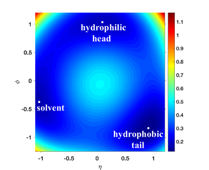
The values of the coefficients specifying the free energy are chosen according to the physical behaviour of the system. After extensive numerical tests, we decided to choose , , and , such that the bulk free energy has three minima as shown in Fig. 1. These minima are located at for hydrophobic tail, for hydrophilic head and for solvent. We further assume and . Our numerical solutions showed that this choice of the parameters produced reasonable solutions corresponding to self-assembled bilayer membranes.
III Numerical Method
Within the framework of the phase field model, the task of studying stable and metastable structures of the model system is to obtain solutions of the Euler-Lagrange equation of the free energy functional, that is, to obtain solutions minimizing the free energy. For the free energy functional given above, the Euler-Lagrange equations are specified by
Instead of solving this set of nonlinear and non-local equations directly, it is more efficient to obtain the solutions using a dynamic approach. Because the phase fields of our model are conserved order parameters satisfying the constraints and , the most convenient dynamic model is the Cahn-Hilliard model designed for conserved order parameters. Accordingly, the stable and metastable structures of our phase field model are obtained as the steady-state solutions of two coupled dynamic equations,
| (5) | ||||
where and are mobility coefficients that will be set as in our numerical calculations. Furthermore, for convenience we have defined two nonlinear terms specified by,
Starting from a given initial configurations, the phase fields will be evolved according to the the dynamic equations of Eq.5. The steady-states of the dynamic equations are then taken as solutions, corresponding to different stable or metastable structures, of the phase field model.
The dynamic phase field model specified above is a generic model valid in any spatial dimensions. However, the results reported in the paper were obtained by carrying out numerical calculations of the system in two-dimension. This choice was made because the main focus of the current paper is to construct the phase field model based on molecular information and to demonstrate the validity of the model using simple examples. Specifically, our simulations were carried out in a two-dimensional domain of the size . The computational domain is discretized using a 128256 square lattice with periodic boundary conditions. We use a first-order semi-implicit scheme in time with . The discrete dynamic equations are given by,
where is the current value of and , and is their next updated value. The nonlinear terms are defined by and .
In order to obtain transition pathways connecting different local minima of the phase field model and the corresponding energy barrier of the transitions, the string methodweinan2002string ; weinan2007simplified , which is an effective numerical method to obtain minimum energy paths (MEPs) corresponding to the most probable transition pathways, is applied to our model free energy functional. It is noted that the string method has been successfully used on particle model to investigate the transition between two opposed membranes to a stalkmuller2012transition and to field-theoretical model to study the pore formationting2018metastable . One complication of applying the string method is that our phase fields are conserved order parameters, so that the computation of MEP and critical nucleus is subject to the constraint and . This constraint could be treated using constrained string methoddu2009constrained . It is noted that several equivalent formulations such as the Lagrange multiplier method or the augmented Lagrange multiplier method could also be used to obtain MEPs. Since we have used Cahn-Hillard equations to find the stable and metastable states, it is effective and natural to apply Cahn-Hilliard type dynamics rather than the Allen-Cahn dynamics with additional Lagrange multiplier. We also notice that this method has been proposed in li2017finding .
In the numerical implementation of the string method, the initial string is constructed using a linear interpolation parameterization connecting the two minima of the system.
Specifically, the two ends are specified by the two minima, which are then used to generate the intermediate nodes.
Let , denotes the i-th node on the string at n-th time step, the steps to obtain the MEP are as follows:
-
•
Step 1 : evolution of the string according to the Cahn-Hilliard equations.
-
•
Step 2 : string reparametrization with a linear interpolation which conserves concentration parameter. The arc lengths corresponding to the current images are given by,
The mesh is then obtained by normalizing . The new string with equal arc length spacing, , is obtained by using linear interpolation from the data .
-
•
Finally, the string of morphologies converges to the MEP.
For a given steady-state string corresponding to a MEP connecting two minima, the node with highest free energy represents the transition state. This state is an unstable saddle point and the energy barrier between the two minima can be calculated by the energy difference between the initial reactant and the transition state.
IV Numerical Results: Equilibrium Structures and Fusion Pathways
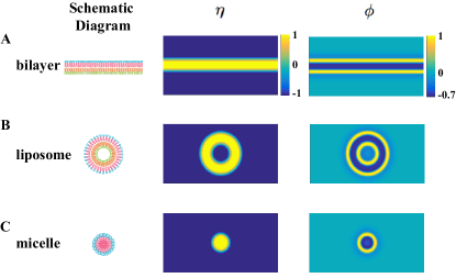
Under different conditions (such as the electrolyte or lipid concentration, pH, and temperature), lipids can associate into various structures in aqueous solutions. As the conditions change, the self-assembly structure could transform from one to anotherisraelachvili2011intermolecular . In the phase field model, the parameters controlling the equilibrium structures are the average concentration of the amphiphiles, . At different values of , different equilibrium structures were obtained. Specifically, a planar bilayer structure (Fig. 2A) is obtained as a stable state of the free energy when . Decreasing the value of results in the formation of a liposome (Fig. 2B), i.e., a spherical vesicle with one bilayer as the steady state. Further decreasing leads to the formation of a micelle (Fig. 2C) as the minimizer of the free energy. In the micelle, the hydrophobic tail are packed in the core surrounded by the hydrophilic heads. The fact that these different structures have been obtained as solutions minimizing the free energy of our phase field model demonstrates that our model system is capable of describing the equilibrium structures of amphiphilic solutions.
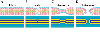
The first step of membrane fusion is to bring them into close contact. It is believed that certain fusion peptides embedded in the membranes play an important role in this initial step chernomordik2003protein ; cai2017liquid . In the current work, we assume that this initial step has already been accomplished such that two opposed bilayers have been brought into close contact. For a model system composed of two opposite membranes in close proximity, the phase field model admits four steady-state solutions shown in Fig. 3 corresponding to (1) opposite bilayers (Fig. 3A), (2) stalk (Fig. 3B), (3) diaphragm (Fig. 3C) and (4) fusion pore (Fig. 3D). For the case of two opposite bilayers in close contact (Fig. 3A), there are no solvent molecules between the membranes. The hydrophilic heads in the opposed cis leaves are in close contact, forming a sandwich-like structure with one hydrophilic layer between two hydrophobic layers. The stalk shown in Fig. 3B is an hourglass-like structure, in which the hydrophilic and hydrophobic layers are deformed resulting in a hydrophobic bridge. The structural change from two opposite bilayers (Fig. 3A) to a stalk (Fig. 3B) is localized in the central region of the system. It is found that the stalk has the highest free energy among the four steady-state structures which means it is less stable than the other structures. The structure of the diaphragm (Fig. 3C) could be viewed as a stretched stalk with only one bilayer in the middle of the morphology. Finally, the fusion pore (Fig. 3D) is a structure with a pore formed resulting in the fusion of membranes. When the fusion pore is formed, the two vesicles become connected through the pore. It is found that the fusion pore has the lowest free energy among four steady-state structures and is the most stable structures.
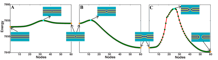
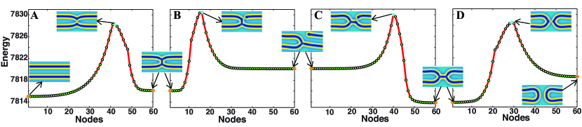
For the case of two bilayers in close contact, a MEP connecting these four steady states (bilayers, stalk, diaphragm and fusion pore) has been obtained by applying the string method to the phase field model. This MEP shown in Fig. 4 corresponds to the complete classical transition pathway and it is the most probable transition path from two opposite bilayer membranes to a fusion pore. Along the transition pathway from bilayers to stalk (Fig. 4A), the membrane becomes thinner in the middle of the system. A critical state, corresponding to the maximum of the energy along the MEP, is reached when the two initially separated hydrophilic regions touch each other (Fig. 4A) initiating a hydrophobic bridge connecting the top and bottom hydrophobic layers. After the critical state, the energy decreases along the MEP when the hydrophobic bridge widens until a stalk structure is formed. The transition from two opposite bilayers to the stalk has been studied by a number of researchers muller2003new ; kuzmin2001quantitative . One noticeable observation is that there is a relatively large energy barrier to form the critical state along this MEP. Therefore the transition from two opposite bilayers to a stalk needs to over come a large energy barrier, thus the process would not occur spontaneously in general. In order to overcome the energy barrier, fusion proteins such as SNARE proteins, synaptotagmin and influenza hemagglutinin are needed, which could be inserted into a membrane to induce local bending martens2008mechanisms ; campelo2008hydrophobic ; kozlov1998mechanism . Along the transition pathway (Fig. 4B) from the stalk to diaphragm, the hydrophobic bridge expands horizontally and shrinks vertically, resulting in the diaphragm composed of a bilayer connecting two sandwich-structures. The transition pathway from the diaphragm to fusion pore is shown in Fig. 4C. It is interesting to note that the pore is not formed by rupturing the bilayer in the middle of the diaphragm. Rather, it is observed that the diaphragm contracts horizontally until a critical state, in which the two bilayers are connected by a nipple-like structure, is reached. After this critical state, a pore is formed connecting two interior sides of the bilayers. The energy of the system decreases as the pore becomes larger until a steady state corresponding to the fusion pore is reached.
In reality, the two opposite bilayers may not be in close contact. In this case a small gap composed of solvent molecules exists between the two bilayers. When there is a gap between the two opposed bilayers, the phase field model still possesses four steady-state solutions corresponding to the state of bilayers (Fig. 5A), stalk (Fig. 5B), diaphragm (Fig. 5C) and fusion pore (Fig. 5D). These structures are similar to the corresponding steady states of the case when two opposite bilayers are in close contact with the exception that there is a gap between the two bilayers. Computationally, the free energy of the phase field model is minimized when the distance between the two bilayers is equal to a fixed value, which depends on the parameters. One can observe that, at the left and right boundaries, the distance between the two bilayers almost stay unchanged during the whole fusion process. Experimentally, a gap between two opposite bilayers could be maintained via a number of mechanisms. In the experiments reported in tamm2003membrane , a fixed distance due to the balance of Van der Waals attraction and hydration repulsion is observed. The distance between electrically neutral bilayers ranges from 1.2 to 2.2nm rand1989hydration , which is about one or two membranes thickness. From the computational results shown in Fig. 5, it is noted that the membranes in stalk (Fig. 5B), diaphragm (Fig. 5C) and fusion pore (Fig. 5D) are heavily curved when compared to the structures in Fig. 3. The large bending of the bilayers is caused by the distance between the two membranes. In the stalk (Fig. 5B) and diaphragm (Fig. 5C) configurations, as the membranes were dented, differently curved monolayers contact each other. However, the hydrophobic tails could not be compactly arranged where hydrophobic interstices are formed as indicated by the red circles in Fig. 5.

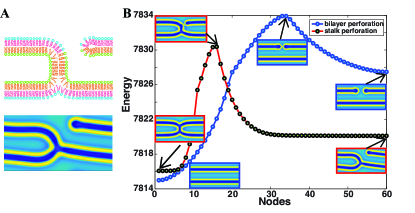
The existence of hydrophobic interstices will hinder the transition between the stalk and diaphragm configurations. We tried to obtain a rotationally symmetric MEP for the case of two opposite bilayers with a gap between them and discovered that there exists an unstable high-energy intermediate state between the stalk and diaphragm in which the two interstices merge into a relatively large one. When the condition of rotational symmetry is relaxed, we obtained a steady state corresponding to a new stalk-hole complex composed of a hole near stalk (Fig. 6A). Previous simulations muller2003new have shown that the formation of holes is correlated in time and space with the formation of stalks and the presence of a stalk encourages a hole to form nearby. The existence of a stalk-hole complex as a steady state along the MEP is consistent with these simulations. It is informative to compare the energy barrier of bilayer perforation MEP with stalk perforation MEP (Fig. 6B). The energy of the stalk-hole steady state is lower than bilayer-hole steady state, indicating that a hole with a stalk nearby is more stable. The energy barrier of stalk perforation MEP is only of that of bilayer perforation MEP, i.e., the stalk structure facilitates the formation of hole. However, the stalk-hole complex configuration still has higher energy than steady states in Fig. 5.
When the condition of rotational symmetry is not maintained, a different MEP going through the stalk-hole configuration has been obtained. The complete leaky transition pathway shown in Fig. 7A-D is the MEP connecting the steady states corresponding to the bilayers, stalk, stalk-hole complex, diaphragm and fusion pore. In Fig. 7A bulges emerge from the middle of two initially flat bilayers. The shape of the inner cis monolayers and the outer trans monolayers deform simultaneously to maintain a constant thickness of membranes. The cis monolayers touch first with two stretched tips and the hydrophilic core which separates the hydrophobic passage is broken through. When the passage is as wide as one bilayer, a stalk is formed. In Fig. 7B, a hole emerges near the stalk in the upper membrane and the lipid molecules surrounding it are rearranged so that the hydrophobic tails are separated from solvent by hydrophilic heads. With a hole, the inside and outside solvent is connected which means the existence of a leakage. In Fig. 7C, the upper right membrane is connected to lower right membrane. After adjustment, diaphragm is formed. It is noteworthy that the cis leaf and trans leaf mix together. From diaphragm to fusion pore (Fig. 7D), the connection between left and right part changes from one bilayer to a nipple-structure, which is the critical state. After the nipple-structure disappears, the energy is decreasing as the distance between left and right part membrane is larger, until the fusion pore is reached. The energy barrier of the MEP from bilayer to stalk without solvent between two bilayers (Fig. 4A) is greatly lower than that with solvent (Fig. 7A), while the energy barrier of MEP from diaphragm to fusion pore (Fig. 4C) is almost the same as the energy barrier in Fig. 7D. The energy barrier from stalk to diaphragm in the classical transition path (Fig. 4B) compared with that from stalk to diaphragm via stalk-hole complex (Fig. 7B-C) is much lower.
V Conclusion and Discussion
In this work, we propose a molecular-informed phase field model for the study of structural transitions of self-assembled bilayers from amphiphilic molecules dissolved in hydrophilic solvents. We emphasize that, in order to describe the details of the bilayer structures, the phase field model has to be developed using information of the molecular properties of the system. In the case of amphiphilic molecules dissolved in solvents, the fact that an amphiphilic molecule is composed of hydrophilic and hydrophobic parts requires a model system which is capable of describing the microscopic phase separation of the hydrophilic heads and hydrophobic tails. We introduce two phase fields to describe macroscopic solvent/amphiphile separation and microscopic amphiphilic head/tail separation, respectively. The energy functional of the phase field model, or the Landau free energy of the system, is developed by extending the theory of block copolymers proposed by Ohta and Kawasaki. The molecular information is encoded in the phase field energy functional. In particular, the fact that the hydrophilic heads and hydrophobic tails are connected to form one molecule is described by the long-range term of the energy functional. This phase field model is capable of predicting the formation of self-assembled bilayers. A combination of the phase field model and the string method is used to obtain minimum energy paths connecting two opposite bilayers with a fusion pore. In the case of membrane fusion, we obtained two complete transition pathways from two opposed bilayers to fusion pore. When the two opposite bilayers are in close contact, a MEP corresponding to the classical transition pathway is obtained. It is noted that the classical transition path has been proposed previously. The results obtained in the current work are in agreement with available results. When the two opposite bilayers are separated by a small gap, a different MEP, corresponding to a leaky transition pathway is obtained. This MEP is characterized by the presence of a stalk-hole complex as an intermediate state. The structural features and information about phase transition processes, such as transition state and energy barrier, are contained in the results naturally.
Numerical study of the proposed phase field model can be naturally extended to 3D membrane fusion computation. More features of stalk-hole complex configuration would be revealed in 3D calculations and the leaky transition pathway through stalk-hole complex configuration may also be different. More MEPs from two opposed bilayers to a fusion pore should be expected. In the current work, we focus on the model development and validation, and we will leave the extended 3D calculations to future study.
Acknowledgment This work was funded by the National Natural Science Foundation of China No. 11622102, 11861130351, 11421110001 and by the Natural Science and Engineering Research Council (NSERC) of Canada.
References
- [1] L Chernomordik, Michael M Kozlov, and J Zimmerberg. Lipids in biological membrane fusion. The Journal of membrane biology, 146(1):1–14, 1995.
- [2] Jonathan R Monck and Julio M Fernandez. The fusion pore and mechanisms of biological membrane fusion. Current opinion in cell biology, 8(4):524–533, 1996.
- [3] Joshua Zimmerberg and Leonid V Chernomordik. Membrane fusion. Advanced drug delivery reviews, 38(3):197–205, 1999.
- [4] Reinhard Jahn and Helmut Grubmüller. Membrane fusion. Current opinion in cell biology, 14(4):488–495, 2002.
- [5] Lukas K Tamm, Jonathan Crane, and Volker Kiessling. Membrane fusion: a structural perspective on the interplay of lipids and proteins. Current opinion in structural biology, 13(4):453–466, 2003.
- [6] Robert Blumenthal, Michael J Clague, Stewart R Durell, and Richard M Epand. Membrane fusion. Chemical Reviews, 103(1):53–70, 2003.
- [7] MM Kozlov and VS Markin. Possible mechanism of membrane fusion. Biofizika, 28(2):242–247, 1983.
- [8] VS Markin and MM Kozlov. Primary act in the process of membrane fusion. Biofizika, 28:73–78, 1983.
- [9] Yonathan Kozlovsky and Michael M Kozlov. Stalk model of membrane fusion: solution of energy crisis. Biophysical journal, 82(2):882–895, 2002.
- [10] Yonathan Kozlovsky, Avishay Efrat, David A Siegel, and Michael M Kozlov. Stalk phase formation: effects of dehydration and saddle splay modulus. Biophysical journal, 87(4):2508–2521, 2004.
- [11] Yonathan Kozlovsky, Leonid V Chernomordik, and Michael M Kozlov. Lipid intermediates in membrane fusion: formation, structure, and decay of hemifusion diaphragm. Biophysical journal, 83(5):2634–2651, 2002.
- [12] Kirill Katsov, Marcus Mueller, and Michael Schick. Field theoretic study of bilayer membrane fusion. i. hemifusion mechanism. Biophysical journal, 87(5):3277–3290, 2004.
- [13] Rolf J Ryham, Mark A Ward, and Fredric S Cohen. Teardrop shapes minimize bending energy of fusion pores connecting planar bilayers. Physical Review E, 88(6):062701, 2013.
- [14] Kirill Katsov, Marcus Müller, and Michael Schick. Field theoretic study of bilayer membrane fusion: Ii. mechanism of a stalk-hole complex. Biophysical journal, 90(3):915–926, 2006.
- [15] M Müller, K Katsov, and M Schick. A new mechanism of model membrane fusion determined from monte carlo simulation. Biophysical journal, 85(3):1611–1623, 2003.
- [16] Tong Shangguan, Dennis Alford, and Joe Bentz. Influenza virus- liposome lipid mixing is leaky and largely insensitive to the material properties of the target membrane. Biochemistry, 35(15):4956–4965, 1996.
- [17] Pierre Bonnafous and Toon Stegmann. Membrane perturbation and fusion pore formation in influenza hemagglutinin-mediated membrane fusion a new model for fusion. Journal of Biological Chemistry, 275(9):6160–6166, 2000.
- [18] A Ya Dunina-Barkovskaya, AV Samsonov, VS Pivovarov, and VA Frolov. Hemagglutinin-induced fusion of hab2 and plc cells: dynamics of fusion pore conductance. Membr. Cell Biol, 13:567–580, 2000.
- [19] Md Emdadul Haque and Barry R Lentz. Influence of gp41 fusion peptide on the kinetics of poly (ethylene glycol)-mediated model membrane fusion. Biochemistry, 41(35):10866–10876, 2002.
- [20] VA Frolov, A Ya Dunina-Barkovskaya, AV Samsonov, and J Zimmerberg. Membrane permeability changes at early stages of influenza hemagglutinin-mediated fusion. Biophysical journal, 85(3):1725–1733, 2003.
- [21] JinKeun Lee and Barry R Lentz. Evolution of lipidic structures during model membrane fusion and the relation of this process to cell membrane fusion. Biochemistry, 36(21):6251–6259, 1997.
- [22] Kervin O Evans and Barry R Lentz. Kinetics of lipid rearrangements during poly (ethylene glycol)-mediated fusion of highly curved unilamellar vesicles. Biochemistry, 41(4):1241–1249, 2002.
- [23] KV Damodaran, Kenneth M Merz Jr, and Bruce Paul Gaber. Structure and dynamics of the dilauroylphosphatidylethanolamine lipid bilayer. Biochemistry, 31(33):7656–7664, 1992.
- [24] I Carmesin and Kurt Kremer. The bond fluctuation method: a new effective algorithm for the dynamics of polymers in all spatial dimensions. Macromolecules, 21(9):2819–2823, 1988.
- [25] Rüdiger Goetz and Reinhard Lipowsky. Computer simulations of bilayer membranes: self-assembly and interfacial tension. The Journal of chemical physics, 108(17):7397–7409, 1998.
- [26] Leonid Yelash, Marcus Müller, Wolfgang Paul, and Kurt Binder. How well can coarse-grained models of real polymers describe their structure? the case of polybutadiene. Journal of chemical theory and computation, 2(3):588–597, 2006.
- [27] Johannes Diederik van der Waals. The thermodynamic theory of capillarity under the hypothesis of a continuous variation of density. Journal of Statistical Physics, 20(2):200–244, 1979.
- [28] Ryo Kobayashi. Modeling and numerical simulations of dendritic crystal growth. Physica D: Nonlinear Phenomena, 63(3-4):410–423, 1993.
- [29] YL Li and LQ Chen. Temperature-strain phase diagram for ba ti o 3 thin films. Applied physics letters, 88(7):072905, 2006.
- [30] Britta Nestler. A multiphase-field model: sharp interface asymptotics and numerical simulations of moving phase boundaries and multijunctions. Journal of crystal growth, 204(1-2):224–228, 1999.
- [31] Qiang Du, Chun Liu, and Xiaoqiang Wang. A phase field approach in the numerical study of the elastic bending energy for vesicle membranes. Journal of Computational Physics, 198(2):450–468, 2004.
- [32] Xiaoqiang Wang and Qiang Du. Modelling and simulations of multi-component lipid membranes and open membranes via diffuse interface approaches. Journal of mathematical biology, 56(3):347–371, 2008.
- [33] Qiang Du, Chun Liu, Rolf Ryham, and Xiaoqiang Wang. Energetic variational approaches in modeling vesicle and fluid interactions. Physica D: Nonlinear Phenomena, 238(9-10):923–930, 2009.
- [34] Jian Zhang, Sovan Das, and Qiang Du. A phase field model for vesicle–substrate adhesion. Journal of Computational Physics, 228(20):7837–7849, 2009.
- [35] Yuliya G Smirnova, Herre Jelger Risselada, and Marcus Müller. Thermodynamically reversible paths of the first fusion intermediate reveal an important role for membrane anchors of fusion proteins. Proceedings of the National Academy of Sciences, 116(7):2571–2576, 2019.
- [36] Marcus Müller, Yuliya G Smirnova, Giovanni Marelli, Marc Fuhrmans, and An-Chang Shi. Transition path from two apposed membranes to a stalk obtained by a combination of particle simulations and string method. Physical review letters, 108(22):228103, 2012.
- [37] Takao Ohta and Aya Ito. Dynamics of phase separation in copolymer-homopolymer mixtures. Physical Review E, 52(5):5250, 1995.
- [38] Takao Ohta and Kyozi Kawasaki. Equilibrium morphology of block copolymer melts. Macromolecules, 19(10):2621–2632, 1986.
- [39] Edgar Avalos, Takeshi Higuchi, Takashi Teramoto, Hiroshi Yabu, and Yasumasa Nishiura. Frustrated phases under three-dimensional confinement simulated by a set of coupled cahn–hilliard equations. Soft matter, 12(27):5905–5914, 2016.
- [40] Aya Ito. Domain patterns in copolymer-homopolymer mixtures. Physical Review E, 58(5):6158, 1998.
- [41] E Weinan, Weiqing Ren, and Eric Vanden-Eijnden. String method for the study of rare events. Physical Review B, 66(5):052301, 2002.
- [42] E Weinan, Weiqing Ren, and Eric Vanden-Eijnden. Simplified and improved string method for computing the minimum energy paths in barrier-crossing events. Journal of Chemical Physics, 126(16):164103, 2007.
- [43] Christina L Ting, Neha Awasthi, Marcus Müller, and Jochen S Hub. Metastable prepores in tension-free lipid bilayers. Physical Review Letters, 120(12):128103, 2018.
- [44] Qiang Du, Lei Zhang, et al. A constrained string method and its numerical analysis. Communications in Mathematical Sciences, 7(4):1039–1051, 2009.
- [45] Boyan Li, Lei Zhang, Chengliang Li, Qiulin Li, Jun Chen, Guogang Shu, Yuqing Weng, Ben Xu, and Wei Liu. Finding non-classical critical nuclei and minimum energy path of cu precipitates in fe–cu alloys. Modelling and Simulation in Materials Science and Engineering, 25(8):085006, 2017.
- [46] Jacob N Israelachvili. Intermolecular and surface forces. Academic Press, 3 edition, 6 2011.
- [47] Leonid V Chernomordik and Michael M Kozlov. Protein-lipid interplay in fusion and fission of biological membranes. Annual review of biochemistry, 72(1):175–207, 2003.
- [48] Yongqiang Cai, Pingwen Zhang, and An-Chang Shi. Liquid crystalline bilayers self-assembled from rod–coil diblock copolymers. Soft matter, 13(26):4607–4615, 2017.
- [49] Peter I Kuzmin, Joshua Zimmerberg, Yuri A Chizmadzhev, and Fredric S Cohen. A quantitative model for membrane fusion based on low-energy intermediates. Proceedings of the National Academy of Sciences, 98(13):7235 – 7240, 6 2001.
- [50] Sascha Martens and Harvey T McMahon. Mechanisms of membrane fusion: disparate players and common principles. Nature Reviews Molecular Cell Biology, 9(7):543, 5 2008.
- [51] Felix Campelo, Harvey T McMahon, and Michael M Kozlov. The hydrophobic insertion mechanism of membrane curvature generation by proteins. Biophysical journal, 95(5):2325 – 2339, 9 2008.
- [52] Michael M Kozlov and Leonid V Chernomordik. A mechanism of protein-mediated fusion: coupling between refolding of the influenza hemagglutinin and lipid rearrangements. Biophysical Journal, 75(3):1384 – 1396, 9 1998.
- [53] R P Rand and V A Parsegian. Hydration forces between phospholipid bilayers. Biochimica et Biophysica Acta (BBA)-Reviews on Biomembranes, 988(3):351 – 376, 12 1989.