Zeeman-splitting-induced Topological Nodal Structure and Anomalous Hall Conductivity in ZrTe5
Abstract
We investigate the topological nodal structure of three-dimensional (3D) ZrTe5 driven by Zeeman splitting as a function of the direction of external magnetic (B) field by using a Wannier-function-based tight-binding (WFTB) model obtained from first-principles calculations. It is known that small external stimuli can drive 3D ZrTe5 into different topological phases including Dirac semimetal. In order to emphasize the effect of Zeeman splitting, we consider 3D ZrTe5 in a strong TI phase with a small band gap. With Zeeman splitting greater than the band gap, the WFTB model suggests that a type-I nodal ring protected by (glide) mirror symmetry is formed when the B field aligns with the crystal or axes, and that a pair of type-I Weyl nodes are formed otherwise, when conduction and valence bands touch. We show that a pair of Weyl nodes can disappear through formation of a nodal ring, rather than requiring two Weyl nodes with opposite chirality to come together. Interestingly, a type-II nodal ring appears from crossings of the top two valence bands when the B field is applied along the axis. This nodal ring gaps out to form type-II Weyl nodes when the B field rotates in the plane. Comparing the WFTB and linearized model, we find inadequacy of the latter at some field directions. Further, using the WFTB model, we numerically compute the intrinsic anomalous Hall conductivity induced by Berry curvature as a function of chemical potential and B field direction. We find that increases abruptly when the B field is tilted from the axis within the plane. Our WFTB model also shows significant anomalous Hall conductivity induced by avoided level crossings even in the absence of Weyl nodes.
I Introduction
Among various three-dimensional (3D) topological materials, ZrTe5 is unique in that small volume changes Weng et al. (2014); Fan et al. (2017), small strains Mutch et al. (2019); Zhang et al. (2017a), or even moderate temperature Xu et al. (2018) can induce a topological phase transition from weak to strong topological insulator (TI) phase. This unique aspect may be attributed to the fact that a single ZrTe5 layer is a two-dimensional (2D) TI Weng et al. (2014). Before the experimental discovery of weak TI, -type bismuth iodide (Bi4I4) Noguchi et al. (2019), ZrTe5 was a first realistic candidate for a weak TI. In order to drive the material from a weak to strong TI by external means, the band gap must be closed at a critical value, which manifests Dirac semimetal Yang and Nagaosa (2014). However, this Dirac semimetal phase is not protected by crystal rotational symmetry like Na3Bi and Cd3As2 Wang et al. (2012, 2013); Yang and Nagaosa (2014) or by nonsymmorphic group symmetry like -cristobalite BiO2 Young et al. (2012). The sensitivity of the topological phase to small changes of the lattice constant or temperature, places this material as an ideal playground for exploring effects of external stimuli on topological properties. Furthermore, such sensitivity resulted in experimental observations of weak TI Zhang et al. (2017a); Xiong et al. (2017); Lv et al. (2018), strong TI Zhang et al. (2017a); Manzoni et al. (2016), and Dirac semimetal phases Zhang et al. (2017b); Chen et al. (2015); Wang et al. (2018) in 3D ZrTe5.
Recent magnetotransport experiments on 3D ZrTe5 showed interesting features including a large anomalous Hall effect as a function of the orientation of external magnetic (B) field (despite the absence of magnetic order) Liang et al. (2018); Ge et al. (2019) as well as 3D quantum Hall effect and metal-insulator transition Tang et al. (2019). In general the intrinsic anomalous Hall effect requires contributions of nonzero Berry curvature from occupied bands Xiao et al. (2010); Nagaosa et al. (2010). When the B field is rotated out of plane, the anomalous Hall resistivity was observed to abruptly increase in an antisymmetric fashion or reveal strong asymmetry as a function of the field orientation Liang et al. (2018). On the other hand, for the in-plane B field, the anomalous Hall resistivity was observed to show clear antisymmetry as a function of the field orientation Liang et al. (2018). The latter feature cannot be explained by the planar Hall effect Nandy et al. (2017); Burkov (2017) alone. Theoretical efforts have been so far mostly limited to understanding topological nodal structures using lowest-order effective models when the B field is parallel to the crystal axes Chen et al. (2015). Very recently, Burkov Burkov (2018) proposed an effect of mirror anomaly on the intrinsic anomalous Hall conductivity (AHC) for Dirac semimetals when the B field rotates. The anomalous Hall effect observed in Ref. Liang et al. (2018) has not been theoretically understood yet.
In order to provide insight into the origin of the intriguing anomalous Hall effect, we construct a Wannier-function-based tight-binding (WFTB) model for 3D ZrTe5 from first-principles calculations and investigate topological phase transitions induced by Zeeman splitting while ignoring Landau levels. The magnitude of the B field is fixed such that the Zeeman splitting is greater than a small band gap, while the B field direction is varied within the crystal , , and planes. The WFTB model predicts that a pair of type-I Weyl nodes are formed for any direction of B field except for when the B field is parallel to the or axes, considering crossings of the conduction and valence bands. This pair of Weyl nodes abruptly transforms into a nodal ring when the B field aligns with the or axis, which conceptually differs from annihilation of Weyl nodes with opposite chirality at the same point. Interestingly, when the top two valence bands cross, the WFTB model suggests type-II topological nodal structures depending on the direction of B field. We also show that the linearized model is not enough to capture even qualitatively correct nodal structures for some B field directions. We numerically compute the intrinsic AHC as a function of the orientation of B field and chemical potential, using the WFTB model. Our results can be compared with the experimental antisymmetric component of the intrinsic out-of-plane AHC as a function of the tilting angle.
We present the crystal structure and symmetries of ZrTe5 in Sec. II and construction of the WFTB model in Sec. III. We show the calculated band structures using the WFTB model in the presence of B field and discuss the induced topological phases as a function of B-field direction in Sec. IV. We compare our findings from the WFTB model with those from the linearized model in Sec. V. Then we present and analyze the calculated AHC as a function of B-field direction and chemical potential in Sec. VI. We summarize our conclusions in Sec. VII.
II Crystal Structure and Symmetries
II.1 Crystal structure
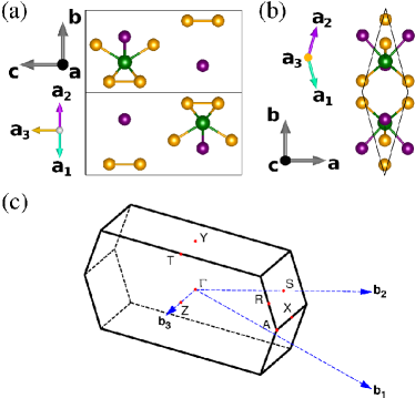
Bulk ZrTe5 crystallizes in the orthorhombic structure with space group (No. 63), , where the experimental lattice constants are , , and Å Fjellvåg and Kjekshus (1986). A primitive unit cell [Fig. 1(a) and (b)] contains two Zr and ten Te atoms. The Zr atoms (green) are located at Wyckoff position , and the two Te atoms (purple) and eight Te atoms (orange) are at and , respectively. Each 2D zigzag layer connected along the and axes is well separated by and stacked along the axis with weak van der Waals interaction. Each Zr atom is bonded with eight Te atoms [Fig. 1(b)]. We consider the following Bravais lattice vectors for the primitive unit cell: a1=(,,0), a2=(,,0), a3=(0,0,) in Cartesian coordinates. In our convention, the , , and axes are the , , and axes in Cartesian coordinates. The corresponding reciprocal lattice vectors are: b1=2(,,0), b2=2(,,0), and b3=2(0,0,). The first Brillouin zone (BZ) is shown in Fig. 1(c), where =(0,,0), =(0,0,0), =(0,0,), =(0,,), =(,,0), and =(,,), in fractional coordinates. These high-symmetry points are equivalent to , , , , , and in Ref.Weng et al. (2014), respectively. The zone boundary point is located at (,,0), where .
In order to examine the effect of Zeeman splitting, we apply 0.25% compressive uniaxial stress along the axis to the DFT-relaxed unstrained geometry while keeping the volume fixed, such that ZrTe5 remains in a strong TI phase with a small band gap in the presence of spin-orbit-coupling (SOC). For reference, the relaxed unstrained lattice constants are , , and Å. In the strained case, the lattice constants are , , and Å. The results obtained from the WFTB model correspond to the 0.25% strained structure.
II.2 Symmetries
3D ZrTe5 has inversion symmetry as well as the following crystal symmetries: two-fold rotational symmetries along the and axes ( and ), two-fold screw symmetry along the axis, mirror symmetries about the and planes (, ), and glide mirror symmetry about the plane (). Since the inversion center does not coincide with the origin of the rotational symmetries, the space group is nonsymmorphic. Inversion symmetry persists even in the presence of B field. Depending on the direction of B field, the following symmetries can survive: (screw) symmetry about the B field direction and the (glide) mirror symmetry about the plane perpendicular to the B field, or where is symmetry about the direction perpendicular to the B field, and is the time-reversal operator.
III Construction of Wannier-function tight-binding model
We first calculate the electronic structure of bulk strained ZrTe5 without SOC and field by using the density-functional theory (DFT) code VASP Kresse and Furthmüller (1996, 1996). With the DFT-calculated band structure and initial atomic orbitals, we generate Wannier functions (WFs) by using Wannier90 Mostofi et al. (2014). Then we construct a SOC-free tight-binding model from the WFs and add atomic-like SOC to the tight-binding model such that the model-calculated band structure agrees with the DFT result. Last, we add Zeeman energy to the tight-binding model.
III.1 Initial DFT calculations
We perform the DFT calculations using VASP Kresse and Furthmüller (1996, 1996) within the Perdew-Burke-Ernzerhof (PBE) generalized-gradient approximation (GGA) Perdew et al. (1996) for the exchange-correlation functional with and without SOC. We use projector augmented wave (PAW) pseudopotentials Blöchl (1994) with an energy cutoff of 350 eV and a Monkhorst-Pack -point mesh. For the experimental geometry Fjellvåg and Kjekshus (1986), our DFT calculation shows that bulk ZrTe5 with SOC is in a strong TI phase with a direct band gap of about 100 meV. The structure with 0.25% compressive strain along the axis has a band gap of 2.2 meV. All calculated band structures from the WFTB model correspond to the strained structure, unless specified otherwise.
III.2 SOC-free Hamiltonian
In order to construct the SOC-free WFTB model, we start with an initial set of 40 projected atomic orbitals comprised of , , , , and orbitals centered at two Zr sites and , , and orbitals centered at ten Te sites in the primitive unit cell. We need to include both Zr orbitals and Te orbitals in the WFTB model due to their large contributions to valence and conduction bands, respectively, near indicated by our DFT calculations. With the VASP-calculated Bloch eigenvalues and eigenstates, we compute the overlap matrix and projection matrix at each DFT-sampled point by using Wannier90 Mostofi et al. (2014); Marzari and Vanderbilt (1997); Souza et al. (2001). We apply the disentanglement procedure within the outer energy window eV relative to the Fermi level. In this energy window, the number of Bloch bands ranges from 43 to 47, and both occupied and unoccupied bands are included. We check that the generated WFs are close to pure atomic orbitals with only real components. In order to maintain the features of the atomic orbitals, maximal localization is not applied in the wannierization.
Now we construct the SOC-free WFTB model by using the generated WFs, , centered at , where are Bravais lattice vectors and denote the sites of orbital (1,…,40). The SOC-free Hamiltonian matrix Marzari and Vanderbilt (1997) reads
| (1) | |||||
| (2) | |||||
| (3) |
where are Bloch states over the crystal momentum space. Here is a hopping or tunneling parameter from orbital at site in the home cell at to orbital at site in the unit cell located at .
III.3 Addition of SOC and Zeeman energy
We add on-site SOC to the home-cell terms since the generated WFs are close to the atomic orbitals that we project onto. Considering the spin degrees of freedom, the number of WFs (basis set functions) is now 80. The SOC Hamiltonian becomes , where is the SOC parameter, is the orbital angular momentum, and represent Pauli spin matrices. We find that with eV and eV, the WFTB calculated band structure agrees well with the VASP-calculated band structure, especially near the point in the vicinity of the Fermi level.
We add the B field as a Zeeman term only and do not include the Peierls phase in the hopping parameters because Landau levels are ignored in our calculations. Then the Zeeman interaction reads , where is the effective electronic factor, is Bohr magneton and is the spin angular momentum. The WFTB model has the following Hamiltonian:
| (4) |
Hereafter we consider the Zeeman interaction energy of 10 meV unless specified otherwise. Experimental data on ZrTe5 indicates that the factor is highly anisotropic. The factor when B field is along the axis () is 21.3 Liu et al. (2016); Chen et al. (2015), whereas the factor for the axis () is about 3.19 Liu et al. (2016). The factor for the axis () was not reported. Therefore, for B field along the axis, the Zeeman energy of 10 meV corresponds to a B field of about 16 T, considering that the Zeeman energy can be expressed as . As long as the Zeeman energy is greater than the band gap, the topological phase transitions presented in this work can be realized. For the strained case, the band gap of 2.2 meV implies a requisite minimum B field of 3.6 T when the B field is applied along the axis.
III.4 Comparison of WFTB-calculated to DFT-calculated band structure with and without SOC
In the absence of the Zeeman term, we compare the DFT-calculated band structure of bulk strained ZrTe5 to the WFTB-calculated result with and without SOC, as shown in Fig. 2. Without SOC, the valence and conduction bands meet linearly at a Dirac point along the direction or axis. The WFTB-calculated band structure agrees well with the DFT result up to about 1.0 eV from the Fermi level. With SOC, a small band gap of 2.2 meV opens up at which is also reliably captured by the WFTB model. We calculate the 3D topological indices (; ,,) Fu and Kane (2007) of strained ZrTe5 using the DFT-calculated wave function. For the reciprocal vector , we find that (; ,,)=(1;110). Since , strained ZrTe5 is a strong TI. Each band is at least doubly degenerate due to the inversion and time-reversal symmetries. In the plane, the four time-reversal invariant points are fourfold degenerate due to the additional mirror symmetry .
IV Zeeman-splitting induced topological phases from WFTB model
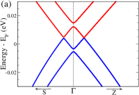
In the presence of B field, we diagonalize the Hamiltonian matrix, Eq. (4), with the same points as the DFT calculation. We examine the topological properties and evolution of the nodal structure as a function of B-field direction for a fixed Zeeman energy of 10 meV with an isotropic factor () for simplicity. We consider cases that the B field is applied along the , , and axes as well as in the , , and planes. The energy window of interest is [-0.12,+0.05] eV relative to the Fermi level , considering that the bulk ZrTe5 samples studied in Ref. Liang et al. (2018) are slightly hole-doped. Within this energy window, the following three types of gapless crossings are in principle possible: crossings between the bottom two conduction bands, crossings between the bottom conduction and top valence bands, and crossings between the top two valence bands. However, we do not find crossings between the bottom two conduction bands for any B-field directions. We focus on the latter two types of crossing only.
IV.1 Magnetic field along the axis: Nodal-ring semimetal
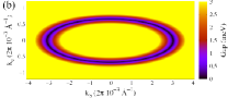
Figure 3(a) shows the WFTB-calculated band structure along the direction near in the vicinity of the Fermi level, when the B field is applied along the axis. The gapless points are found from crossings between the top valence and bottom conduction bands in the - plane and they form a ring, as shown in Fig. 3(b). Since the two bands meet with opposite slope, this is a type-I nodal ring. Note that with the B field, the relevant remaining symmetries are inversion symmetry, and . From the eigenvectors of the WFTB model, we confirm that the two crossing bands have opposite mirror eigenvalues. The intercepts with the and axes are (0, 0.003072, 0) and (0, 0, 0.000673) Å-1, respectively. The gapless ring is not an equi-energy curve, and no other gapless points are found within the energy window of interest.
In order to identify the topological nature of the gapless ring, we compute the Berry phase around a closed circle interlocking the gapless ring. The Berry phase is defined as a sum of line integrals of the Berry connection of all occupied bands , , over a closed path in space:
| (5) |
where . Here is a periodic function of the Bloch state. We find that the Berry phase is . Thus, the ring of the gapless points is indeed a topological nodal ring.
IV.2 Magnetic field along the axis: Nodal-ring semimetal
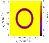
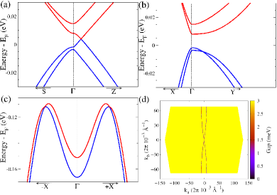
Figure 4(a) shows the calculated band structure along the direction when the B field aligns with the axis. The bottom conduction and top valence bands meet near the Fermi level along the and directions (not shown), whereas a small gap opens up along the direction. Similar to Sec. IV.1, a type-I ring of gapless points is found in the - plane near in the vicinity of the Fermi level [Fig. 4(b)]. The gapless points intercept the and axes at (0.000743, 0, 0) and (0, 0, 0.000840) Å-1. We expect that the gapless crossings are allowed because the two crossing bands have opposite glide mirror eigenvalues. We find that the Berry phase is ; the gapless ring is a topological nodal ring. No other gapless crossings are found in the energy window of interest.
IV.3 Magnetic field along the axis: Weyl or type-II nodal-ring semimetal
When the B field aligns with the axis, the valence and conduction bands meet with opposite slope along the -axis at (0, 0, 0.000624) 2Å-1 in the vicinity of the Fermi level as shown in Fig. 5(a). We evaluate the topological charge associated with the gapless points by computing the Berry curvature using the method discussed in WannierTools Wu et al. (2018) and Ref. Villanova and Park (2018). The Berry curvature can be calculated as Wang et al. (2007)
| (6) |
where . Here and are the -th eigenvector and eigenvalue of [Eq. (4)], and is the Levi-Civita tensor without a sum over . The topological charge of each gapless point (arising from a crossing of band and band ) is then calculated by enclosing it in a small sphere ,
| (7) |
where is a unit vector normal to . We find that the topological charge associated with the gapless points are , respectively, and so they are type-I Weyl points. The two Weyl points are related by inversion symmetry.
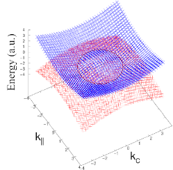
In addition, we find that the top two valence bands touch in the vicinity of the Fermi level, as shown in Fig. 5(b) and (c). The gapless points form a nodal ring in the - plane [Fig. 5(d)]. There are two interesting features of this ring. First, the band dispersion near the gapless point has the same slope along the and axes, and so it is referred to as a type-II nodal ring. Note that the nodal ring discussed earlier in Secs.IV.1 and IV.2 is of type-I. Second, the type-II nodal ring extends to the neighboring BZ, forming a closed thin cigar shape. The size of the type-II nodal ring is much larger than the type-I nodal rings discussed in Secs.IV.1 and IV.2. We evaluate the Berry phase around the circle interlocking the ring, finding that it is indeed ; the ring is topologically protected by symmetry.
IV.4 Magnetic field in the plane
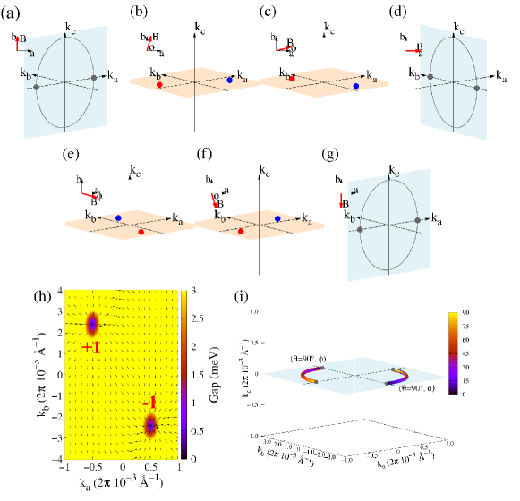
Figure 6(a)-(g) schematically shows the evolution of the type-I nodal ring and Weyl points as the B field rotates in the plane. When the B field is slightly rotated from the axis in the plane, the WFTB model shows that the type-I nodal ring in the - plane is abruptly gapped out (due to broken mirror symmetry) everywhere but two gapless points, transforming into a pair of type-I Weyl nodes () lying in the - plane. As the polar angle between the B field and the axis further decreases, the Weyl points initially close to the axis evolve toward the axis in the - plane. Then when the B field aligns with the axis (), the pair of Weyl points suddenly transforms into a nodal ring in the - plane (with the restoration of a mirror symmetry). As the B field continues to rotate clockwise beyond the positive axis (), the nodal ring transforms into a pair of Weyl points where the chirality of the Weyl points is now exchanged. For example, Fig. 6(h) exhibits the calculated Berry curvature with a pair of Weyl nodes obtained from the WFTB model at . Figure 6(i) summarizes the calculated evolution of the nodal ring and Weyl points as a function of for 0 , where the intercepts with the and axes become part of the nodal rings (not drawn) when and , respectively.
In contrast to a common belief, our result demonstrates that there is another way to annihilate Weyl points other than bringing a pair of Weyl points with opposite chirality to the same point. This possibility was earlier discussed within effective models in the case of Dirac semimetals in the presence of B field Burkov (2018). Furthermore, our finding indicates that the chirality of the Weyl nodes can be exchanged with the reversal of the component of the B field.
IV.5 Magnetic field in the or plane
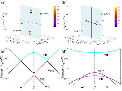
When the B field is rotated from the axis in the plane, we find that the pair of type-I Weyl nodes with (arising from the conduction and valence bands) move somewhat away from the axis and return to the axis as the angle approaches , where is the angle between the B field and the axis. See Fig. 7(a). Then when the B field aligns with the axis, the type-I Weyl points [Fig. 7(c)] abruptly transform into the type-I nodal ring in the - plane, as discussed earlier. For , a pair of Weyl nodes reappear with the reversed topological charges compared to those in the case of , similarly to Sec. IV.4. The transformation of the Weyl nodes into a nodal ring is related to the mirror anomaly Burkov (2018), which is discussed later in Sec. V.3.
On the other hand, the type-II nodal ring arising from the top two valence bands is now completely gapped out except for two type-II gapless points [Fig. 7(d)] when the B field is rotated from the axis in the plane. For example, the type-II Weyl nodes occur at (0, 0.002140, 0.000025) Å-1 at . We confirm that the type-II gapless points have topological charge , using the method discussed in Ref. Soluyanov et al. (2015). The type-II Weyl nodes with opposite chirality are brought closer to each other as increases. They are eventually annihilated when approaches about 40∘ [Fig. 7(b)].
When the B field is rotated from the axis in the plane, we find that the pair of type-I Weyl nodes with (arising from the conduction and valence bands) remain almost along the axis with only slight changes in their locations. Then when the B field is parallel to the axis, the Weyl nodes transform into a nodal ring. In contrast to the case with the B field in the plane, there are no crossings from the top two valence bands in this case.
IV.6 Summary of topological phases from WFTB model
Table 1 summarizes the topological phases found from the WFTB model. In the next section, we discuss the linearized model and the topological phases predicted from the model. We also compare the findings from the WFTB model and those from the model.
| Direction \ Model | WFTB (CB-VB) | WFTB (VB-VB) | (CB-VB) |
|---|---|---|---|
| Ba | 1 type-I nodal ring | - | 1 type-I nodal ring |
| Bb | 1 type-I nodal ring | - | 1 type-I nodal ring |
| Bc | 2 type-I Weyl nodes | 1 type-II nodal ring | 2 type-I Weyl nodes |
| B in plane* | 2 type-I Weyl nodes | - | 1 type-I nodal ring |
| B in plane* | 2 type-I Weyl nodes | 2 type-II Weyl nodes† | 2 type-I Weyl nodes |
| B in plane* | 2 type-I Weyl nodes | - | 2 type-I Weyl nodes |
V Comparison with linearized model
V.1 Lowest-order model
The lowest-order Hamiltonian Chen et al. (2015) can be obtained by keeping only linear terms in that satisfy the symmetries of bulk ZrTe5. The Hamiltonian expanded near the point reads
| (8) | |||||
| (9) | |||||
| (10) |
where and are orbital (conduction and valence bands) and spin Pauli matrices. Here and are Fermi velocities and mass (or half of the bulk band gap), respectively. The , , and coordinates correspond to the crystal , , and axes. is the Zeeman interaction where we assume the same isotropic -factors for the conduction and valence bands for simplicity. The symmetry group of ZrTe5 is generated by two mirror reflections, , , inversion and time-reversal symmetries, which are represented by , , , and , respectively ( is complex conjugation).
Equation (8) can be diagonalized for an arbitrary B field with energy eigenvalues given by
| (11) |
where , , , and . In Ref. Chen et al. (2015) only three B field directions (, , and axes) are considered. The energy eigenvalues, Eq. (11), agree with those in Ref. Chen et al. (2015). We find that the conduction and valence bands can cross if the Zeeman splitting energy is greater than the band gap, i.e., , whereas the two conduction (valence) bands can not cross each other for any B field directions. The resulting nodal structure is summarized in Table 1.
V.2 Comparison between WFTB and lowest-order models
The nodal structure calculated using the WFTB and lowest-order models qualitatively agree with each other in most cases, as listed in Table 1, although the positions of Weyl points or nodal rings may quantitatively differ from each other. The previous study Chen et al. (2015) reported the nodal structure only when the B field aligns with the crystal axes using the lowest-order model. Qualitative discrepancy between the WFTB model and the lowest-order model occurs in two cases: (i) when the top two valence bands meet with each other for the B field along the axis and in the plane and (ii) when the B field lies in the plane (though not along the or axes). The first discrepancy might arise from the observation that Zr orbitals contribute to the top two valence bands by about 20% of the total electron density according to our DFT calculations, whereas the lowest-order model Chen et al. (2015) was constructed based on Te orbitals only. The second discrepancy arises from the extra symmetry imposed on the lowest model due to truncation of higher-order terms.
When the B field aligns with either the or axis, a nodal ring appears in the corresponding mirror plane. Interestingly, in the lowest-order model, we find that this nodal ring persists as long as the B field lies in the plane, even though there is no mirror symmetry that protects the nodal ring when the B field is away from the or axis. For example, Fig. 8 shows the calculated nodal ring using the lowest model when the angle between the B field and the axis is . Compare this figure to the nodal structure obtained from the WFTB model [Fig. 6(h)] for the same B field direction. Our study shows that continuous symmetry is present in the lowest-order model, which rotates both the band structure and the B field together about the axis. This symmetry is represented by
| (12) |
where
| (13) |
and
| (14) |
For simplicity, we assume an isotropic Fermi velocity and an isotropic -factor, but a similar result holds in general cases. However, higher-order terms in the model would break the symmetry, and they would gap out the nodal ring unless there is mirror symmetry. Neither the WFTB model nor the crystal structure of ZrTe5 have such symmetry.
V.3 Mirror anomaly
Recently, Burkov Burkov (2018) has pointed out an additional quantum anomaly referred to as mirror anomaly inherent in Dirac semimetals with mirror symmetry, independent of their type or origin such as topological Yang and Nagaosa (2014), nonsymmorphic Young et al. (2012), or accidental, based on the linearized Dirac Hamiltonian. In a Dirac semimetal, the chirality operator (which projects chirality of the two Weyl fermion components) Burkov (2018, 2017) commutes with only one of the spin components. When the B field rotates from this spin direction to the perpendicular axis with which mirror symmetry is present, the Weyl points abruptly transform into a nodal ring protected by the mirror symmetry. Furthermore, in the Dirac Hamiltonian, the positions of the Weyl nodes do not change with rotation angle until they become the nodal ring. As a consequence, intrinsic AHC was predicted to show a singular behavior as a function of the B field direction.
In the lowest-order model for ZrTe5, Eq. (8), the spin component that commutes with the chirality operator is the or component. Therefore, in the model, the mirror anomaly dictates the abrupt transformation of a pair of Weyl points into a nodal ring as well as singular intrinsic out-of-plane AHC when the B field rotates from the axis to the or axis. The difference between the WFTB model and the model in this context is that the positions of the Weyl points noticeably change with the -field orientation when the field is in the plane in the WFTB model.
VI Intrinsic Anomalous Hall effect
When Weyl points are present at the Fermi level, the material can manifest large AHC despite the point-like Fermi surface, which serves as an important experimental signature for Weyl semimetals. In general, broken time reversal symmetry along with a finite-volume Fermi surface may give rise to nonzero AHC whether Weyl points are present or not.
VI.1 Numerical calculation of AHC
We numerically compute the AHC of ZrTe5 under an external B field based on our WFTB model, as a function of chemical potential as well as the direction of B field. In the next two subsections, we separately present our results in the cases of isotropic and anisotropic factor. We consider because the plane is perpendicular to the stacking direction, which is experimentally the most relevant plane Chen et al. (2015); Liang et al. (2018). We focus on the intrinsic part of the AHC Xiao et al. (2010); Nagaosa et al. (2010) which depends only on the Berry curvature:
| (15) | |||||
| (16) |
where is the Fermi-Dirac distribution with chemical potential , and is the -component of the Berry curvature coming from the -th band. Here is the Chern number (considering all occupied bands) calculated at a given plane. We assume that temperature is zero. Regarding the 3D integral of the whole first BZ in Eq. (15), we perform 2D integrals in the - plane () at fixed planes and integrate the 2D integrals along the direction. In this calculation we separate the first BZ into two regions such as near the point and away from the point, and use a finer (coarser) -mesh for the former (latter) region.
When the Fermi surface is composed of a pair of isolated Weyl points with topological charge , is known to be , where is the separation between the two Weyl points projected onto the axis. This is because each 2D plane parallel to the plane which lies between the two Weyl points contributes Chern number of or to the integral in Eq. (16), whereas the planes which do not lie between the two Weyl points have zero Chern number. In this case, the intrinsic AHC is simply proportional to the separation between the Weyl points along the axis. However, if the Fermi surface has a nonzero volume, there is no such a simple expression for and the AHC must be numerically computed.
Equation (15) enforces that is strictly zero if the B field is parallel to the plane due to the symmetry. The symmetry maps the Berry curvature component into , making the integral in Eq. (15) vanish. Therefore, the nonzero AHC observed in Ref. Liang et al. (2018) for the in-plane B fields (i.e. parallel to the plane) must originate from the non-intrinsic part of the AHC and/or nonlinear effects.
VI.2 Calculated AHC in the case of isotropic factor
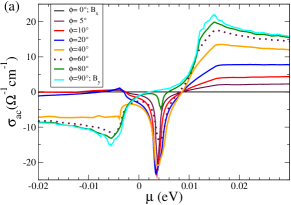

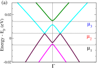
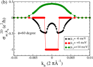
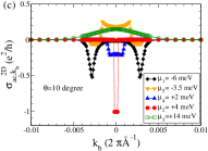
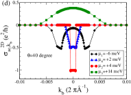
Figure 9(a) shows numerically calculated as a function of chemical potential when the B field rotates in the plane, in the case of isotropic factor. First of all, we find that intrinsic becomes strictly zero independent of the chemical potential value when the B field exactly aligns with the axis due to the symmetry argument provided earlier. Let us first discuss features at chemical potential meV (referred to as ) which coincides with the type-I Weyl point energy. See Fig. 10(a). At this chemical potential, a sharp, prominent (negative) peak appears for all angles except for 0∘ and 90∘. The peak height varies with , as shown in Fig. 9(d). In order to provide more insight, we also calculate at different planes, finding that they are quantized as either 0 or 1 in units of . This result explains both the peak height and the angular evolution of the peak height. The abrupt increase in the peak height is attributed to the large separation of the Weyl point along the axis as the angle increases from zero. The peak height, however, goes to zero smoothly as the angle approaches 90∘ because of the smooth changes of the Weyl point separation. See Fig. 6(i). In addition to the sharp peak, smoothly rising negative and positive peaks appear near +6 meV () and +14 meV () for large angles ( 60∘). See Figs. 9(a), (c), and (e). Note that there are no other Weyl nodes beyond the pair discussed earlier. Now the values for and are not quantized in units of [Fig. 10(b)]. However, they contribute to the value, Eq. (15), via avoided level crossings as shown in Fig. 10(a). Our result is not unusual. For example, in bcc Fe, Co, and Ni, a very large Berry curvature was found in regions where avoided level crossings occur, and it resulted in large AHC Wang et al. (2007).
Now when the B field rotates from the axis in the plane, overall features of [Figs. 9(b), (f)-(h)] are similar to those for the above case, though with some differences. Let us first discuss at chemical potential . At this chemical potential, the height of the negative peak can be up to an order of magnitude smaller than that for the above case, as shown in the inset of Fig. 9(b) and Fig. 9(g). The values are quantized as either 0 or 1 in units of . For example, Fig. 10(c) and (d) show such quantization for and 40∘. The observed peak height of also corroborates the contributions of the type-I Weyl points which evolve with the angle as illustrated in Fig. 7(a). Next, for meV, the flat region arises from contributions of small nonzero values near . See upward-triangles in Fig. 10(c) and (d). Last, at meV a small positive peak appears only for small angles ( 40∘). This peak is associated with the type-II Weyl nodes arising from the crossings of the two valence bands. See Fig. 7(d). At higher angles, the type-II Weyl points with opposite chirality are annihilated, and the peak vanishes accordingly.
VI.3 Calculated AHC in the case of anisotropic factor
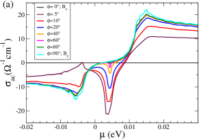
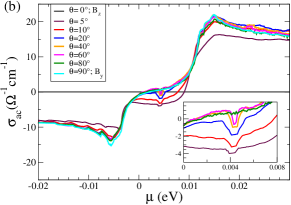
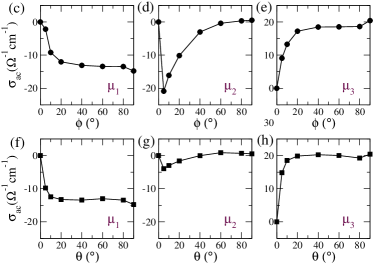
Figure 11(a) shows our calculated as a function of and , using the following anisotropic factors: =3.19 Liu et al. (2016), =21.3 Chen et al. (2015); Liu et al. (2016), and =2.0. In this case, the Zeeman energy remains to be fixed as 10 meV. In other words, =10 meV. When the B field rotates from the axis in the plane, the height of the sharp AHC peak at abruptly increases with the angle and then it immediately starts to decrease. See Fig. 11(d). On the other hand, the height of the smooth peaks at and sharply increases with the angle and then it saturates at a small angle. See Fig. 11(c) and (e). These features can be explained using the Weyl-point positions and avoided level crossings, similarly to the case of isotropic factor.
A similar trend appears when the B field is tilted in the plane [Figs. 11(b), (f)-(h)]. One small difference is shown in the inset of Fig. 11(b). The small AHC peak at vanishes for very large angles such as 80 90∘, because the component of the Weyl point position becomes zero.
Overall the angular dependence of with the anisotropic factor qualitatively differs from that with the isotropic factor in both and planes. This is attributed to a much larger contribution of the component of B field for a given angle. For the same reason, with the anisotropic factor, the type-II Weyl nodes are not formed except for extremely small angles away from the axis. Note that the type-II Weyl nodes with opposite chirality are annihilated at 40∘ in the case of isotropic factor.
VII Conclusion
In summary, we develop a WFTB model for 3D ZrTe5 from first-principles calculations, considering both Zr and Te orbitals. Based on the WFTB model, we investigate Zeeman-splitting induced topological phases and the evolution of the topological nodal structures as a function of the orientation of B field (beyond the crystal axes). We find an abrupt transformation of a nodal ring to a pair of Weyl nodes as the B field is rotated from either the crystal or axis. At some B field directions type-II nodal structures are identified from crossings of the valence bands. Comparing the calculated topological phases with those from the linearized model, we find that the latter model does not capture the correct topological phases when the B field is rotated in the or in plane. We also numerically compute the intrinsic part of the AHC, , as a function of chemical potential, when the B field is tilted within the or plane. The calculated results can be compared to the experimental data when the experimental anomalous Hall resistivity is properly converted into , which requires the knowledge of longitudinal resistivity. Our findings may also provide insight into Zeeman-splitting-induced topological phases and their consequences in other Dirac semimetals with mirror symmetries.
Acknowledgements.
Y.C. was supported by the Virginia Tech ICTAS Fellowship. The computational support was provided by San Diego Supercomputer Center (SDSC) under DMR060009N and VT Advanced Research Computing (ARC).References
- Weng et al. (2014) H. Weng, X. Dai, and Z. Fang, Phys. Rev. X 4, 011002 (2014).
- Fan et al. (2017) Z. Fan, Q.-F. Liang, Y. B. Chen, S.-H. Yao, and J. Zhou, Sci. Rep. 7, 45667 (2017).
- Mutch et al. (2019) J. Mutch, W.-C. Chen, P. Went, T. Qian, I. Z. Wilson, A. Andreev, C.-C. Chen, and J.-H. Chu, Sci. Adv. 5, eaav9771 (2019).
- Zhang et al. (2017a) Y. Zhang, C. Wang, L. Yu, G. Liu, A. Liang, J. Huang, S. Nie, X. Sun, Y. Zhang, B. Shen, J. Liu, H. Weng, L. Zhao, G. Chen, X. Jia, C. Hu, Y. Ding, W. Zhao, Q. Gao, C. Li, S. He, L. Zhao, F. Zhang, S. Zhang, F. Yang, Z. Wang, Q. Peng, X. Dai, Z. Fang, Z. Xu, C. Chen, and X. J. Zhou, Nat. Commun. 8, 15512 (2017a).
- Xu et al. (2018) B. Xu, L. X. Zhao, P. Marsik, E. Sheveleva, F. Lyzwa, Y. M. Dai, G. F. Chen, X. G. Qiu, and C. Bernhard, Phys. Rev. Lett. 121, 187401 (2018).
- Noguchi et al. (2019) R. Noguchi, T. Takahashi, K. Kuroda, M. Ochi, T. Shirasawa, M. Sakano, C. Bareille, M. Nakayama, M. D. Watson, K. Yaji, A. Harasawa, H. Iwasawa, P. Dudin, T. K. Kim, M. Hoesch, V. Kandyba, A. Giampietri, A. Barinov, S. Shin, R. Arita, T. Sasagawa, and T. Kondo, Nature 566, 518 (2019).
- Yang and Nagaosa (2014) B.-J. Yang and N. Nagaosa, Nat. Commun. 5, 4898 (2014).
- Wang et al. (2012) Z. Wang, Y. Sun, X.-Q. Chen, C. Franchini, G. Xu, H. Weng, X. Dai, and Z. Fang, Phys. Rev. B 85, 195320 (2012).
- Wang et al. (2013) Z. Wang, H. Weng, Q. Wu, X. Dai, and Z. Fang, Phys. Rev. B 88, 125427 (2013).
- Young et al. (2012) S. M. Young, S. Zaheer, J. C. Y. Teo, C. L. Kane, E. J. Mele, and A. M. Rappe, Phys. Rev. Lett. 108, 140405 (2012).
- Xiong et al. (2017) H. Xiong, J. A. Sobota, S.-L. Yang, H. Soifer, A. Gauthier, M.-H. Lu, Y.-Y. Lv, S.-H. Yao, D. Lu, M. Hashimoto, P. S. Kirchmann, Y.-F. Chen, and Z.-X. Shen, Phys. Rev. B 95, 195119 (2017).
- Lv et al. (2018) Y.-Y. Lv, B.-B. Zhang, X. Li, K.-W. Zhang, X.-B. Li, S.-H. Yao, Y. B. Chen, J. Zhou, S.-T. Zhang, M.-H. Lu, S.-C. Li, and Y.-F. Chen, Phys. Rev. B 97, 115137 (2018).
- Manzoni et al. (2016) G. Manzoni, L. Gragnaniello, G. Autès, T. Kuhn, A. Sterzi, F. Cilento, M. Zacchigna, V. Enenkel, I. Vobornik, L. Barba, F. Bisti, P. Bugnon, A. Magrez, V. N. Strocov, H. Berger, O. V. Yazyev, M. Fonin, F. Parmigiani, and A. Crepaldi, Phys. Rev. Lett. 117, 237601 (2016).
- Zhang et al. (2017b) J. L. Zhang, C. Y. Guo, X. D. Zhu, L. Ma, G. L. Zheng, Y. Q. Wang, L. Pi, Y. Chen, H. Q. Yuan, and M. L. Tian, Phys. Rev. Lett. 118, 206601 (2017b).
- Chen et al. (2015) R. Y. Chen, Z. G. Chen, X.-Y. Song, J. A. Schneeloch, G. D. Gu, F. Wang, and N. L. Wang, Phys. Rev. Lett. 115, 176404 (2015).
- Wang et al. (2018) J. Wang, J. Niu, B. Yan, X. Li, R. Bi, Y. Yao, D. Yu, and X. Wu, Proc. Natl. Acad. Sci. USA 115, 9145 (2018).
- Liang et al. (2018) T. Liang, J. Lin, Q. Gibson, S. Kushwaha, M. Liu, W. Wang, H. Xiong, J. A. Sobota, M. Hashimoto, P. S. Kirchmann, Z.-X. Shen, R. J. Cava, and N. P. Ong, Nat. Phys. 14, 451 (2018).
- Ge et al. (2019) J. Ge, D. Ma, Y. Liu, H. Wang, Y. Li, J. Luo, T. Luo, Y. Xing, J. Yan, D. Mandrus, H. Liu, X. C. Xie, and J. Wang, (2019), arXiv:1905.06040 .
- Tang et al. (2019) F. Tang, Y. Ren, P. Wang, R. Zhong, J. Schneeloch, S. A. Yang, K. Yang, P. A. Lee, G. Gu, Z. Qiao, and L. Zhang, Nature 569, 537 (2019).
- Xiao et al. (2010) D. Xiao, M.-C. Chang, and Q. Niu, Rev. Mod. Phys. 82, 1959 (2010).
- Nagaosa et al. (2010) N. Nagaosa, J. Sinova, S. Onoda, A. H. MacDonald, and N. P. Ong, Rev. Mod. Phys. 82, 1539 (2010).
- Nandy et al. (2017) S. Nandy, G. Sharma, A. Taraphder, and S. Tewari, Phys. Rev. Lett. 119, 176804 (2017).
- Burkov (2017) A. A. Burkov, Phys. Rev. B 96, 041110 (2017).
- Burkov (2018) A. A. Burkov, Phys. Rev. Lett. 120, 016603 (2018).
- Fjellvåg and Kjekshus (1986) H. Fjellvåg and A. Kjekshus, Solid State Commun. 60, 91 (1986).
- Kresse and Furthmüller (1996) G. Kresse and J. Furthmüller, Phys. Rev. B 54, 11169 (1996).
- Kresse and Furthmüller (1996) G. Kresse and J. Furthmüller, Comput. Mater. Sci. 6, 15 (1996).
- Mostofi et al. (2014) A. A. Mostofi, J. R. Yates, G. Pizzi, Y.-S. Lee, I. Souza, D. Vanderbilt, and N. Marzari, Comput. Phys. Commun. 185, 2309 (2014).
- Perdew et al. (1996) J. P. Perdew, K. Burke, and M. Ernzerhof, Phys. Rev. Lett. 77, 3865 (1996).
- Blöchl (1994) P. E. Blöchl, Phys. Rev. B 50, 17953 (1994).
- Marzari and Vanderbilt (1997) N. Marzari and D. Vanderbilt, Phys. Rev. B 56, 12847 (1997).
- Souza et al. (2001) I. Souza, N. Marzari, and D. Vanderbilt, Phys. Rev. B 65, 035109 (2001).
- Liu et al. (2016) Y. Liu, X. Yuan, C. Zhang, Z. Jin, A. Narayan, C. Luo, Z. Chen, L. Yang, J. Zou, X. Wu, S. Sanvito, Z. Xia, L. Li, Z. Wang, and F. Xiu, Nat. Commun. 7, 12516 (2016).
- Fu and Kane (2007) L. Fu and C. L. Kane, Phys. Rev. B 76, 045302 (2007).
- Wu et al. (2018) Q. Wu, S. Zhang, H.-F. Song, M. Troyer, and A. A. Soluyanov, Comput. Phys. Commun. 224, 405 (2018).
- Villanova and Park (2018) J. W. Villanova and K. Park, Phys. Rev. B 98, 075123 (2018).
- Wang et al. (2007) X. Wang, D. Vanderbilt, J. R. Yates, and I. Souza, Phys. Rev. B 76, 195109 (2007).
- Soluyanov et al. (2015) A. A. Soluyanov, D. Gresch, Z. Wang, Q. Wu, M. Troyer, X. Dai, and B. A. Bernevig, Nature 527, 495 (2015).