Towards third-order parametric down-conversion in optical fibers
Abstract
Optical fibers have been considered an optimal platform for third-order parametric down-conversion since they can potentially overcome the weak third-order nonlinearity by their long interaction length. Here we present, in the first part, a theoretical derivation for the conversion rate both in the case of spontaneous generation and in the presence of a seed beam. Then we review three types of optical fibers and we examine their properties in terms of conversion efficiency and practical feasibility.
I Introduction
Optical fibers have proved to be extremely efficient platforms for generating non-classical states Takesue2004 ; Rarity2005 ; Li2005 ; Fan2005 . Whilst bulk materials and, more recently, waveguides are also good candidates for generating single- or two-photon states, the size and, most importantly, the length of both is limited technically. Optical fibers overcome this problem, the only real constraints on their length being given by the optical loss and the homogeneity.
Direct generation of photon triplet states via the cubic interaction has been a long standing goal in the field of quantum optics dating as far back as the 1980’s Braunstein1987 ; Elyutin1990 ; Felbinger1998 ; Douady2004 ; Chekhova2005 ; Gravier2008 ; Corona2011 ; Moebius2016 ; Cavanna2016 ; Gonzalez2018 . The interest to this process, known as third-order parametric down-conversion (TOPDC), is driven by the fact that such interaction leads to the direct generation of a non-Gaussian state Braunstein1987 . It realizes a three-mode squeezing operator that differs greatly from the two-mode squeezing operator that generates Gaussian squeezed states. Photon triplet states generated directly through the cubic interaction were observed only at microwave frequencies chang2019observation . The photon triplet states generated so far at optical frequencies were mediated by the second-order susceptibility Huebel2010 ; Guerreiro2014 . In the absence of post-selection they do not display any non-Gaussian features.
In this work we estimate the efficiency of TOPDC in various fibers that have previously been suggested as promising platforms. Because the expected rates of three-photon emission are in most cases tiny, we also consider the case where TOPDC is seeded at the frequency of one of the three emitted photons. Seeding dramatically increases the rate of two-photon emission in the two remaining modes. Although the output state of these modes in this case is expected to be the same Okoth2019 as for the usual two-photon spontaneous parametric down-conversion (SPDC), seeding can be used to study the TOPDC spectral features, similar to the way stimulated emission tomography (SET) Liscidini2013 is used to characterize SPDC.
II Theory
For a monochromatic pump, the rate of transitions from the vacuum state to non-degenerate three-photon state that occupies modes 1, 2 and 3 is given by the Fermi golden rule,
| (1) |
where is the final three-photon state, is the initial vacuum state, is the Hamiltonian, and . The subscript denotes the state with frequency and propagation constant . Accounting for the possible transition to several sets of modes as opposed to a single discrete three-mode state, we integrate Eq. (1) over a set of wavevector intervals. The rate of transitions into this set of intervals is then
| (2) |
where is the quantization length. Using the dipole approximation and the third-order non-linear response gives the Hamiltonian Okoth2019
| (3) |
where is the effective cubic susceptibility, is the volume of the cubic interaction, is the vacuum permittivity. The fields and relate to the pump and modes and , respectively, the +(-) denote their positive (negative) frequency components. Please note that here we ignore terms for cross and self phase modulation in the Hamiltonian and reintroduce them at a later stage as their effect on the phase matching is well documented Agrawal2012 . We describe strong macroscopic fields such as the pump (p) and later the seed (s) classically,
| (4) |
whilst the weak fields in modes we describe using the quantum field operators
| (5) |
Here, is the propagation direction in the fiber, the subscript denotes the field mode with frequency , propagation constant , refractive index , and group velocity , is the photon creation operator. The normalized transverse field distribution , where is the unnormalized transverse field distribution 111 are vectors but we omit vector notation for simplicity. The field amplitudes are given by
| (6) | |||
| (7) |
where is the power and the speed of light.
II.1 Unseeded TOPDC
Substituting Eqs. (4,5) into the Hamiltonian (3) and integrating over the volume gives
| (8) |
Here we have introduced the effective mode area as
| (9) |
and the phase matching function as
| (10) |
where is the fiber length and the propagation constant mismatch is given by
| (11) |
Here we account for the cross and self phase modulation terms, which we dropped from the Hamiltonian, by reintroducing a non-linear momentum mismatch term , where is the nonlinear coefficient for the pump self-phase modulation,
| (12) |
and is the nonlinear coefficient for cross-phase modulation,
| (13) |
The effective mode area for the pump self phase modulation is
| (14) |
whereas for the cross phase modulation term the effective mode area between the pump and the photon triplet is
| (15) |
It is worth noting that if the peak pump power is low, for example if one works in the continuous-wave (CW) regime, then the cross and self modulation terms are negligible. Substituting Eq. (8) into Eq. (2) gives the following differential rate of triplet emission:
| (16) |
where the nonlinear coefficient is
| (17) |
Eq. (16) can be rewritten in terms of frequency as opposed to propagation constant, using the relation for group velocity , as
| (18) |
Because the rate of unseeded TOPDC scales linearly with the pump power, CW regime is more favourable in this case. Working in the pulsed regime would lead to competing non-linear processes that scale non-linearly with the pump power. Light from such processes could saturate detectors or interfere with the spontaneous generation of triplets.
II.2 Seeded TOPDC
Stimulation of TOPDC requires a seed beam in one of the triplet modes, 1, 2 or 3. In all the cases below we choose to replace mode 3 with the seed, which we will denote by the subscript s. If the seed beam is strong then it can be described by a classical field, hence the Hamiltonian in Eq. (8) can be rewritten as
| (19) |
Here, the classical amplitude of the seed is defined by Eq. (6) with . From this it is clear that when a seed is present, the three-photon state is lost and instead a two-photon state is generated Okoth2019 . Since we now consider the product of two classical fields there is an advantage in using a pulsed source. If the seed and pump pulses are overlapped spatially and temporally, then their product averaged over time will introduce an enhancement factor equivalent to the inverse duty cycle of the laser.
In the pulsed regime the monochromatic approximation breaks down and the Fermi golden rule must be rewritten. Assuming a square pulse, the probability of a two-photon transition occurring over the pulse duration is
| (20) |
where
| (21) |
Again integrating over a set of wavevector intervals gives the differential number of transitions per pulse:
| (22) |
Expanding out the quantum average gives
| (23) |
where the nonlinear interaction coefficient for the seeded process is
| (24) |
and . Again, for convenience we rewrite Eq. (23) in terms of frequency intervals, which yields
| (25) |
It is worth noting that and have different dimensionality, the former being the number of pairs emitted per pulse (dimensionless) and the latter being a rate of triplet emission (Hz) in the CW regime.
III Estimates and experimental evidence
In order to ensure the efficient generation of photon triplets along the entire fiber length, phase matching has to be fulfilled, see Eq.(11). Normally this can be achieved by the so-called intermodal phase matching, where different fields propagates in the fiber in different spatial modes. In the case of triplet generation phase matching is usually found when the pump at is in a high-order mode while the three photons are in the fundamental mode. Coupling light into a high-order mode is quite challenging and usually not very efficient. Furthermore, there are no free parameters that allow one to tune the dispersion, therefore, for a given optical fiber the phase matching frequencies are fixed. To overcome these two problems we investigated different types of optical fibers. The first one is a hybrid fiber that, due to the use of different guidance mechanisms, allows the phase matching between single-lobed modes. Not only does this simplifies the coupling, but it also increases the overlap between the pump and the generated fields. The second one is a hollow-core fiber filled with xenon gas, which allows tuneable phase matching by changing the gas pressure. Finally, we consider a tapered fiber, which has a high overlap between the two phase matching modes due to their high confinement and whose dispersion can be tuned by changing the gas pressure of the environment Hammer2018 .
III.1 Hybrid fiber
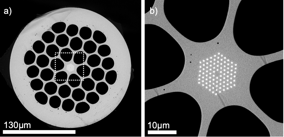
The first fiber that we present is a solid core microstructured fiber with a double core structure Cavanna2016 . This fiber was designed to circumvent the problem of coupling the pump beam into a high-order mode by compensating the phase mismatch using modes of different size, ideally both fundamental. This comes from the fact that the propagation constant of a mode at a fixed wavelength can be decreased by just reducing the mode diameter. The fiber has a photonic bandgap (PBG) structure that guides the visible mode, surrounded by hollow channels. The infrared mode is guided by total internal reflection, the entire PBG structure acts as the core and the surrounding glass, together with the hollow channels, as the cladding. The inner PBG structure contains rods made of high refractive index lead-silicate glass (Schott SF6) embedded in low refractive index glass (Schott LLF1), see Fig. 1 for the scanning electron micrograph (SEM) of the fiber. The central rod of SF6 glass is replaced by one of LLF1 in order to create a defect that corresponds to the core. By carefully tuning the rods diameter and the distance between them (the pitch), it is possible to create a bandgap that confines light at a particular frequency Birks2006 . In our case, the target wavelength is 532 nm. For our fiber we choose a diameter of about 380 nm for the SF6 glass rods and a pitch of 1.05 m. The rods are arranged in a hexagonal geometry with 5 concentric rings. On the one hand, increasing the number of rings will decrease the guidance losses of the visible mode but on the other hand, the dimensions of the PBG structure define the infrared mode size and therefore its dispersion. Fig. 2 shows the dispersion and the intensity distributions of guided modes simulated with the finite-element model (FEM) Cavanna2016 .
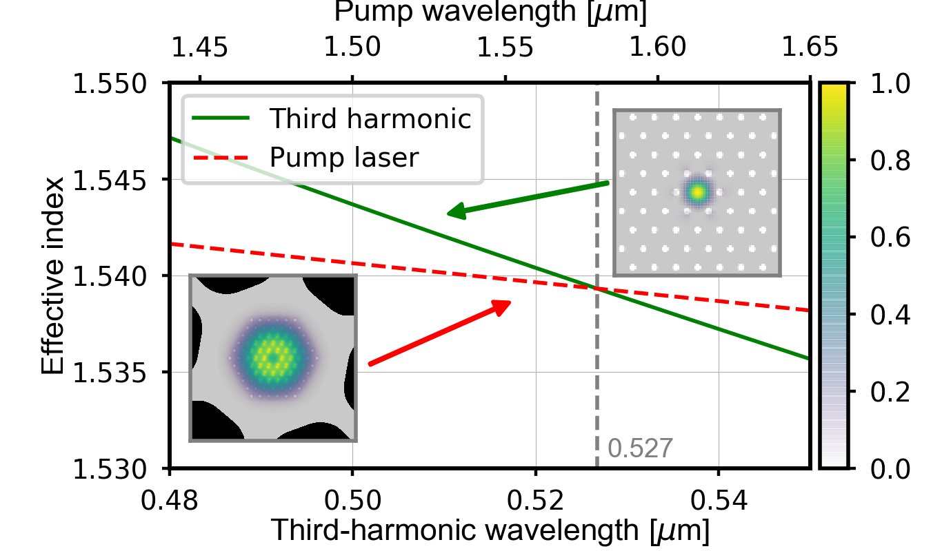
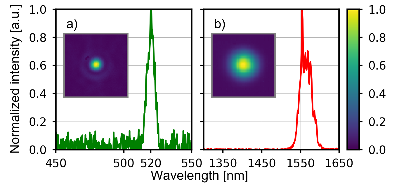
Photon triplet generation can be seen as the reverse process of third harmonic generation (THG), with which it shares, among many features, the phase matching conditions. We therefore used the THG to test the phase matching for the manufactured fiber. Due to the small dimensions it is difficult to precisely control the fiber parameters and achieve phase matching at exactly nm. Therefore we used an optical parametric generator (OPG) pumped with the second harmonic of a Nd:YAG laser ( nm) with ps pulse duration and kHz repetition rate Cavanna2016a . The output of the OPG was tuneable over more than nm with about 10 mW average power. Using this source we generated third-harmonic radiation in the optical fiber. The phase matching wavelength was found at nm and the near field intensity distribution of the mode was measured, see Fig. 3.
Starting from the mode electric fields, obtained with the FEM simulations, we calculated an effective area of m2. We considered the effective third-order susceptibility of SF6 glass m2V-2 boling1978empirical . Using Eq. (18) and assuming a pump power of 100 mW (CW), a length of cm, and a detection bandwidth of nm, we obtained an expected spontaneous triplet generation rate of Hz (Table. 1).
III.2 Gas-filled hollow-core fiber
The second fiber that we present is a gas-filled hollow-core photonic-crystal fiber (PCF). Hollow-core fibers have the great advantage to allow tuneable phase matching by changing the pressure of the filling gas. For our experiment we choose to use Xenon due to its high nonlinearity bree2010method and the very low reactivity. There are several geometries of hollow-core fibers, the one that we consider in this paper is known as single-ring fiber pryamikov2011demonstration ; wei2017negative . It consists of a ring of capillaries attached to the inner surface of a glass tube, see Fig. 4 a).
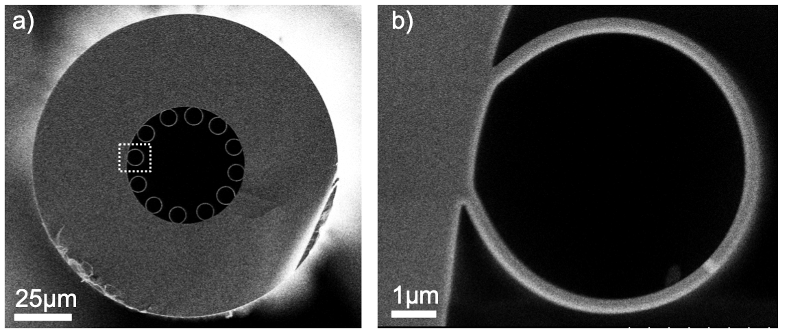
Light is confined in the core region by means of an anti-resonant reflection at the core-cladding interface. The wall-thickness of the glass-capillaries defines the resonant frequencies at which the light is not guided. The dimensions of the capillaries determine the modal guidance of the fiber. The light is guided in the core only if there is no coupling with the capillary modes uebel2016broadband . For triplet generation we require a minimum guidance losses for infrared light around nm in the fundamental mode and at nm for the phase matched high-order mode. Depending on the core diameter, the phase matching can be achieved at different gas pressures Nold2010 . A smaller core size usually implies higher guidance losses but at the same time also a higher gas pressure at which phase matching is achieved and therefore higher nonlinearity. The designed fiber has a core diameter of m surrounded by a ring of 12 capillaries, each with a diameter of m. For this configuration there is no coupling between the visible high-order mode and the capillaries’ modes at the same frequency.
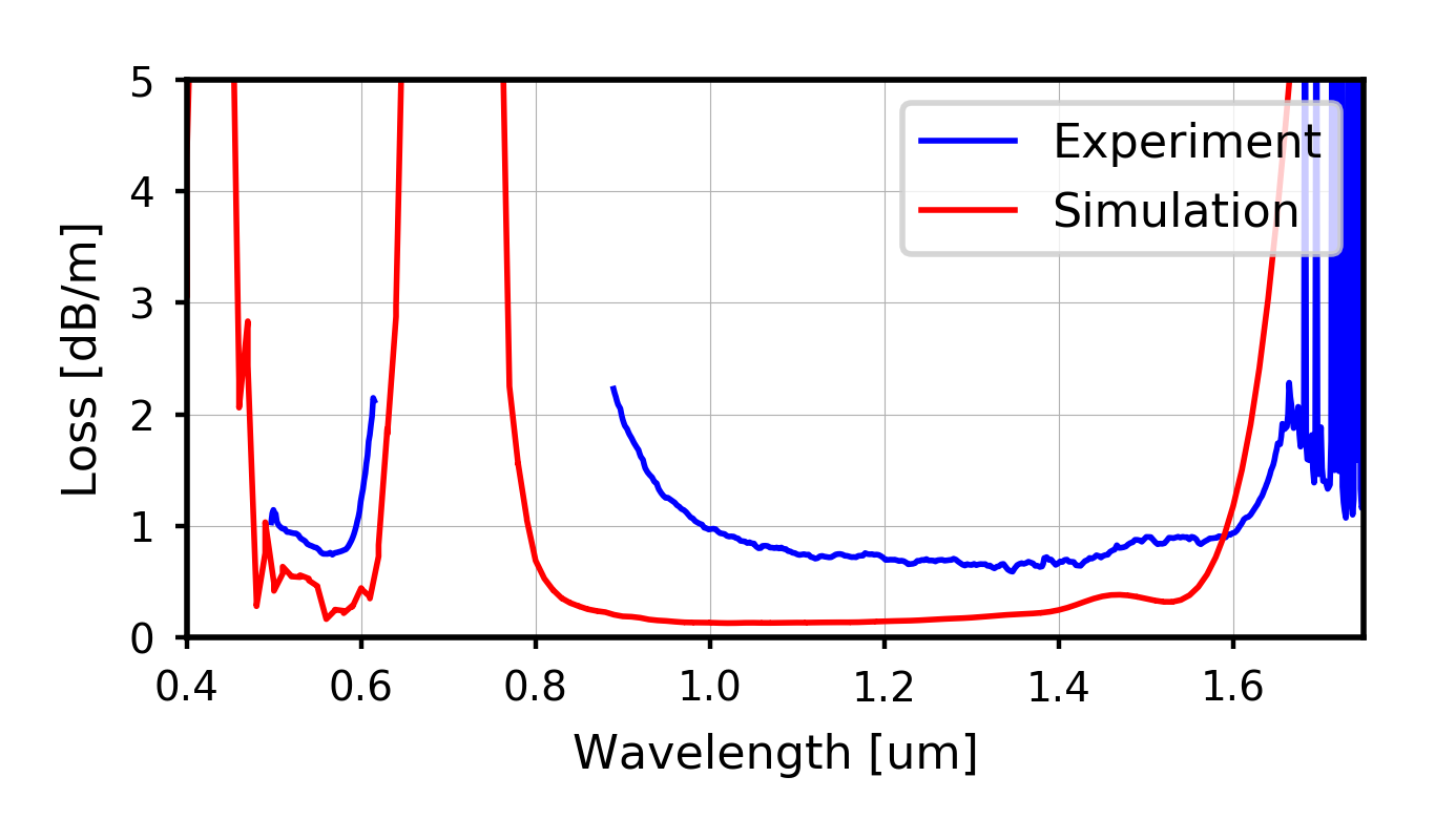
Using the formula given in Refs. archambault1993loss ; zeisberger2017analytic , it is possible to estimate the resonance frequencies for given parameters of the fiber. The glass thickness of the capillaries was chosen to be nm in order to set the resonant frequencies far from the region of interest. Indeed, the drawn fiber, with corresponding glass thickness, has relatively low losses both at nm and around nm. Figure 5 shows that, in agreement with the calculation (red line), the measured (blue line) loss in the ranges of interest does not exceed dB/m.
Using a FEM model of the fiber we simulated the guided modes and their dispersion as a function of the Xe pressure, see Fig. 6. The phase matching was found at bar.
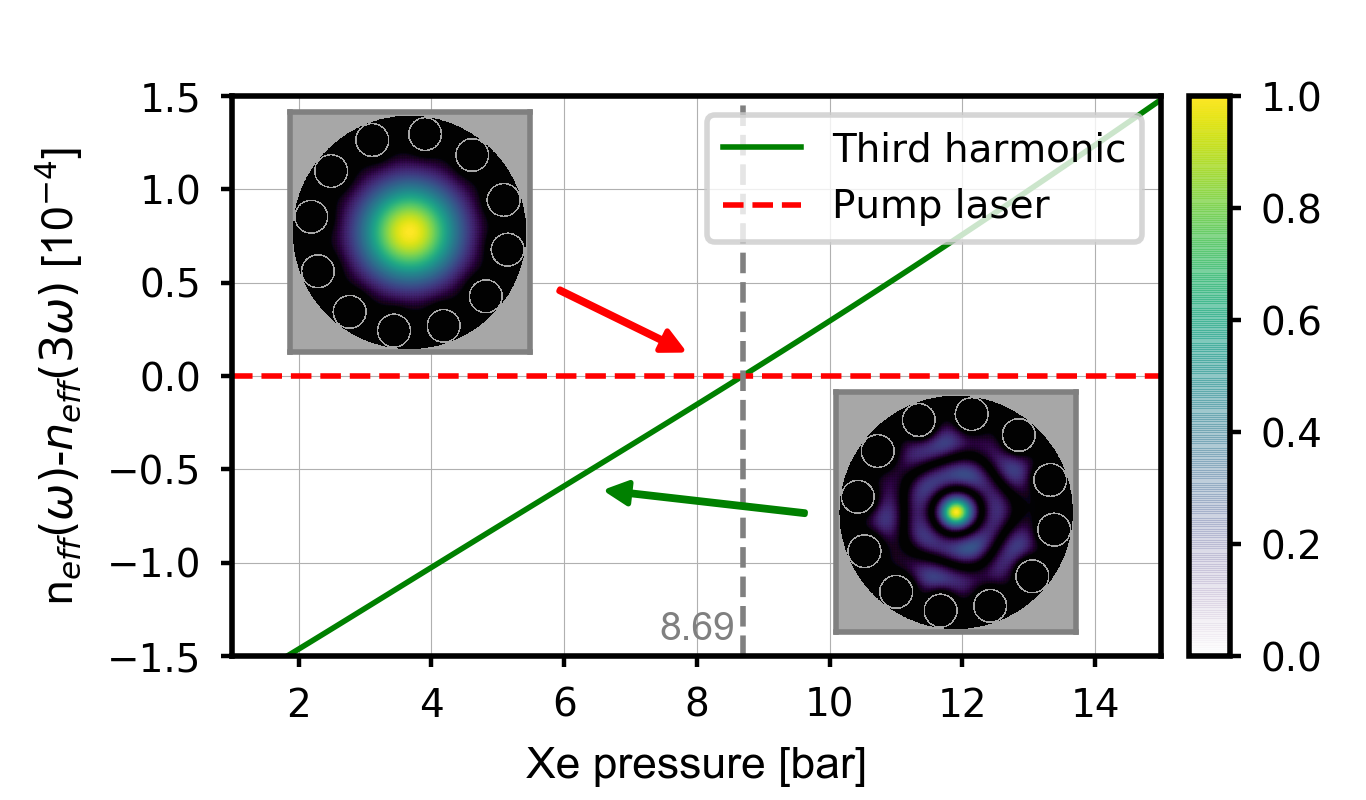
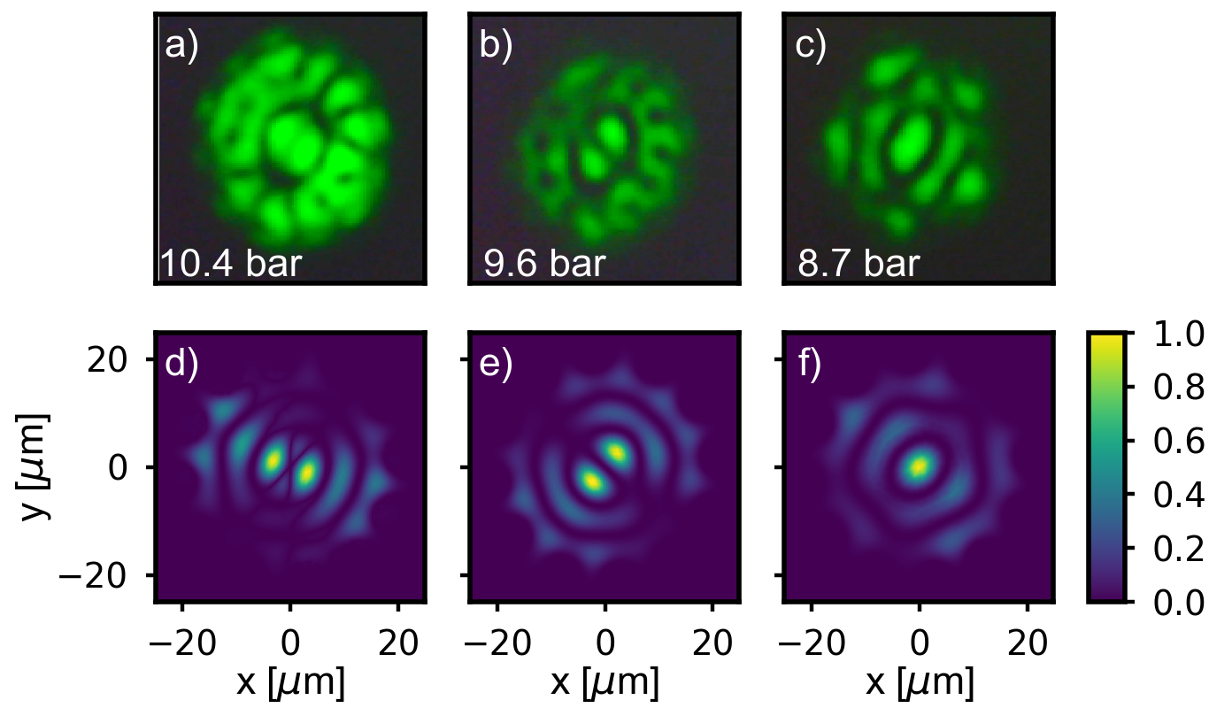
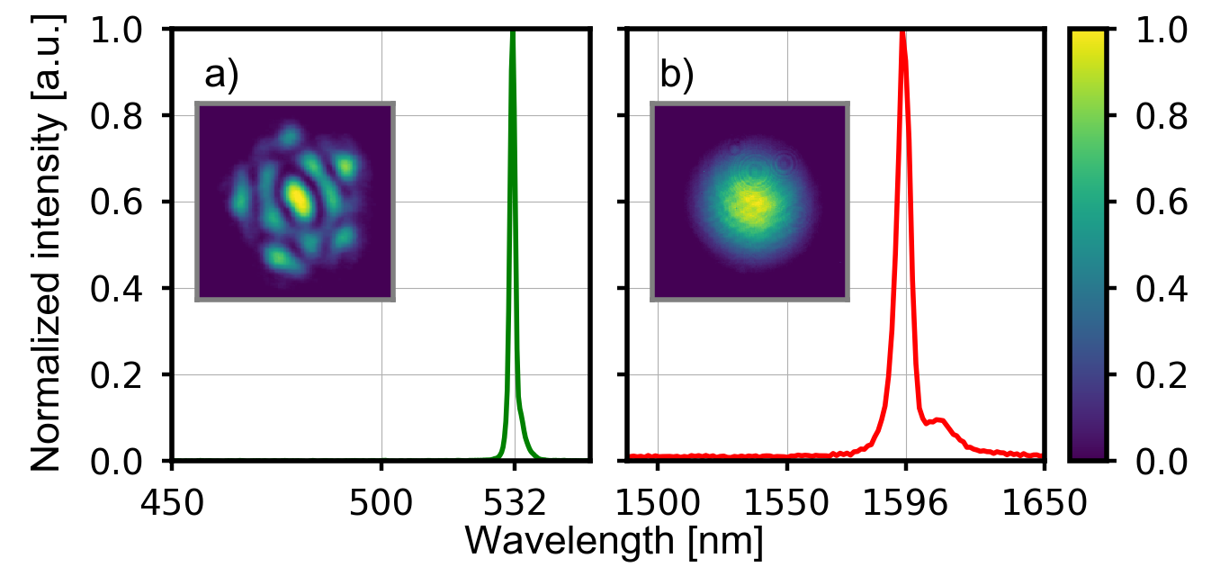
In order to verify the phase matching we coupled the output of our OPG tuned at 1596 nm into the fiber core and observed the THG. To reduce the bandwidth of the pump beam we used a CW seed beam at 1596 nm in the OPG. The fiber was mounted in a gas-cell with a Xe pressure of about bar. By gradually reducing the gas pressure we achieved the THG for different high-order modes at nm, see Fig. 7. Our target mode, i.e. the one of the lowest possible order and therefore with the lowest effective area, was achieved at bar. Figure 8 shows the recorded spectra and the intensity distributions for the targeted mode at nm and the fundamental IR mode.
The third-order nonlinearity of Xenon can be estimated from Refs. bree2010method ; lehmeier1985 m2V-2, where the subscript 0 indicates that the susceptibility was measured at a pressure of bar and at a temperature of degrees. The effective nonlinearity is proportional to the gas pressure, therefore in our system it is about 9 times larger than . It is worth noticing that by reducing the core diameter and improving the fiber design (to reduce the confinement losses) not only the effective area will decrease but also the phase matching will move to higher pressure where the nonlinearity is higher. Due to the relatively low third-order nonlinearity of gases compared to solids, in the hollow-core PCF the spontaneous triplet generation rate is only on the order of Hz for pumping m of fiber with mW (Table. 1). Nevertheless, hollow-core PCF are very suitable for seeded generation, since they can guide very high power without being damaged. The only restrictions are the preparation and the coupling efficiency of the high-order pump mode.
III.3 Tapered fiber
Consider now tapered optical fiber as a platform for photon-triplet generation. Fiber tapers are manufactured by stretching a conventional step-index fiber (SMF28) over a scanning oxybutane flame Birks1992 . Controlling the pulling speed and scanning range allows for a precise control over the taper parameters. Decreasing the diameter of the fiber increases its effective nonlinearity, as well as drastically changes the waveguide contribution to the dispersion. The fiber tapers of interest here have a sub-micron waist diameter. At this diameter the initial fiber core is reduced so much that it does not play any significant role in the guiding mechanism, and the dispersion of the taper waist is given by the dispersion of a silica rod with the corresponding diameter in vacuum. SnyderLove For triplet generation, the use of tapered optical fiber requires inter-modal phase matching similar to the case of gas-filled hollow-core fibers.
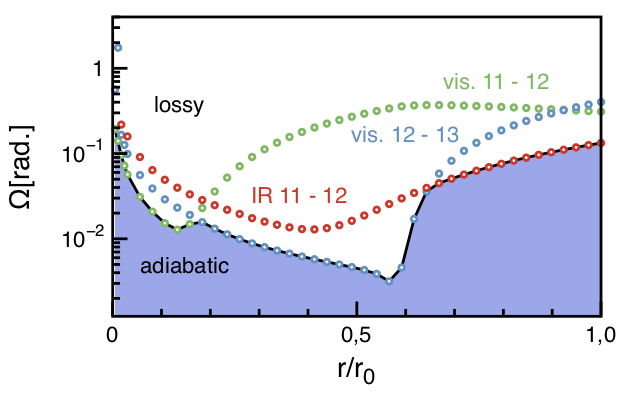
As shown by Corona et al. Corona2011 , the most favourable case occurs when the visible pump light is guided in the HE12 mode and the generated photon triplet-state is in the fundamental mode of the fiber. It is essential to ensure an adiabatic transition for both spatial modes involved in the generation process. Therefore, the transition profile of the taper must be designed very carefully. In particular, the local transition angle must remain small enough to avoid coupling between the fiber modes. The maximum angle allowed for adiabatic mode conversion between the untapered fiber and the taper waist is given by Love86 :
| (26) |
where is the local core radius of the taper, the local wavenumber of the mode to couple into the waist taper and the closest mode, to which coupling should be avoided. Here, we used a finite-difference eigenmode solver to compute the wavenumber for the HE11 and HE12 for the IR and the same two modes plus the HE13 in the visible (Fig. 9). In this calculation the HE and HE are guided at the cladding-air interface at all places along the transition, while the other modes are guided in the core of the un-tapered fiber and evolve into cladding modes along the transition. Using Eq. 26 we can calculate the three different curves in Fig. 9 corresponding to the adiabatic angles avoiding coupling between HE11 and HE12 in both the visible as well as the IR, as well as avoiding coupling between HE12 and HE13 in the visible. The actual transition should always lie below all three curves.
Pumping at nm, the diameter of the waist should be nm for degenerate photon triplet generation. In this case, the effective area and using m2V-2 for silica we can evaluate a generation rate as high as Hz for a cm-long taper with a pump of mW (Table 1).
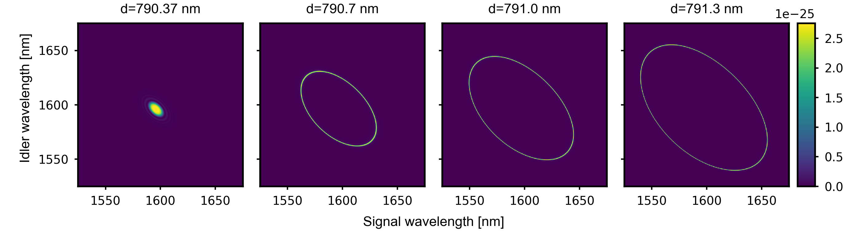
It is important to note that the exact value of the diameter is extremely critical. With the same pumping condition but a tapered waist of nm the phase matching is no longer degenerate and the emission bandwidth is 130 nm (see Appendix). The same effect can be obtained by changing the pump wavelength by about nm. Such stringent fabrication tolerance cannot be met in practice. We can however circumvent this difficulty by encapsulating the tapered fiber inside a gas-cell filled with a gas under adjustable pressure Hammer2018 .
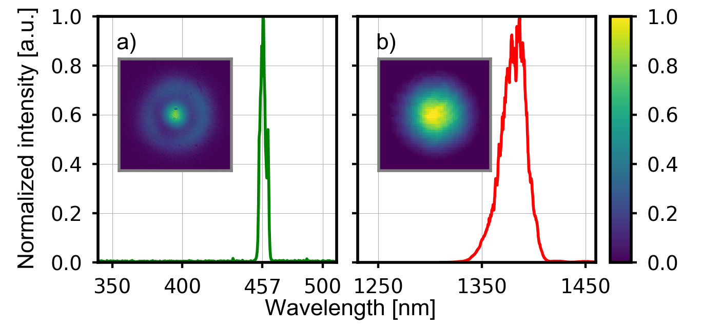
Similarly to the other fibers, third-harmonic generation was measured in the fiber taper. The fiber was pumped with a tunable laser having 0.25 MHz repetition rate, and 160 fs pulse duration and central wavelength 1375 nm, see Fig. 10. The third harmonic was generated at 457 nm in the expected HE12 guided mode.
| Fiber Type | Pump power () | () | Pump Wavelength [] | Effective Area ()[] | Length () [cm] | Detect. bandwidth () [nm] | Triplet Rate [Hz] |
| Hybrid core | 100 mW | 11.5 | 0.526865 | 218 | 10 | 150 | 11 |
| Hollow-core | 200 mW | 0.043 | 0.532 | 19200 | 100 | 150 | |
| Tapered | 20 mW | 2.5 | 0.532 | 7.89 | 10 | 150 | 3.2 |
One of the challenges that we face when employing tapered fibers for TOPDC is the difficulty of coupling the pump at nm preferentially to the HE12 mode. We have explored a solution which involves the use of two different types of fiber, 460HP and SMF28 spliced together, as shown schematically in Fig. 11(a), with the tapered region appearing along the SMF28 stretch of fiber. While the 460HP fiber is characterized by a core diameter of m and is single-mode at nm, the SMF28 fiber with a core radius of m is multi-mode at this wavelength (but single-mode at the TOPDC center wavelength of nm).
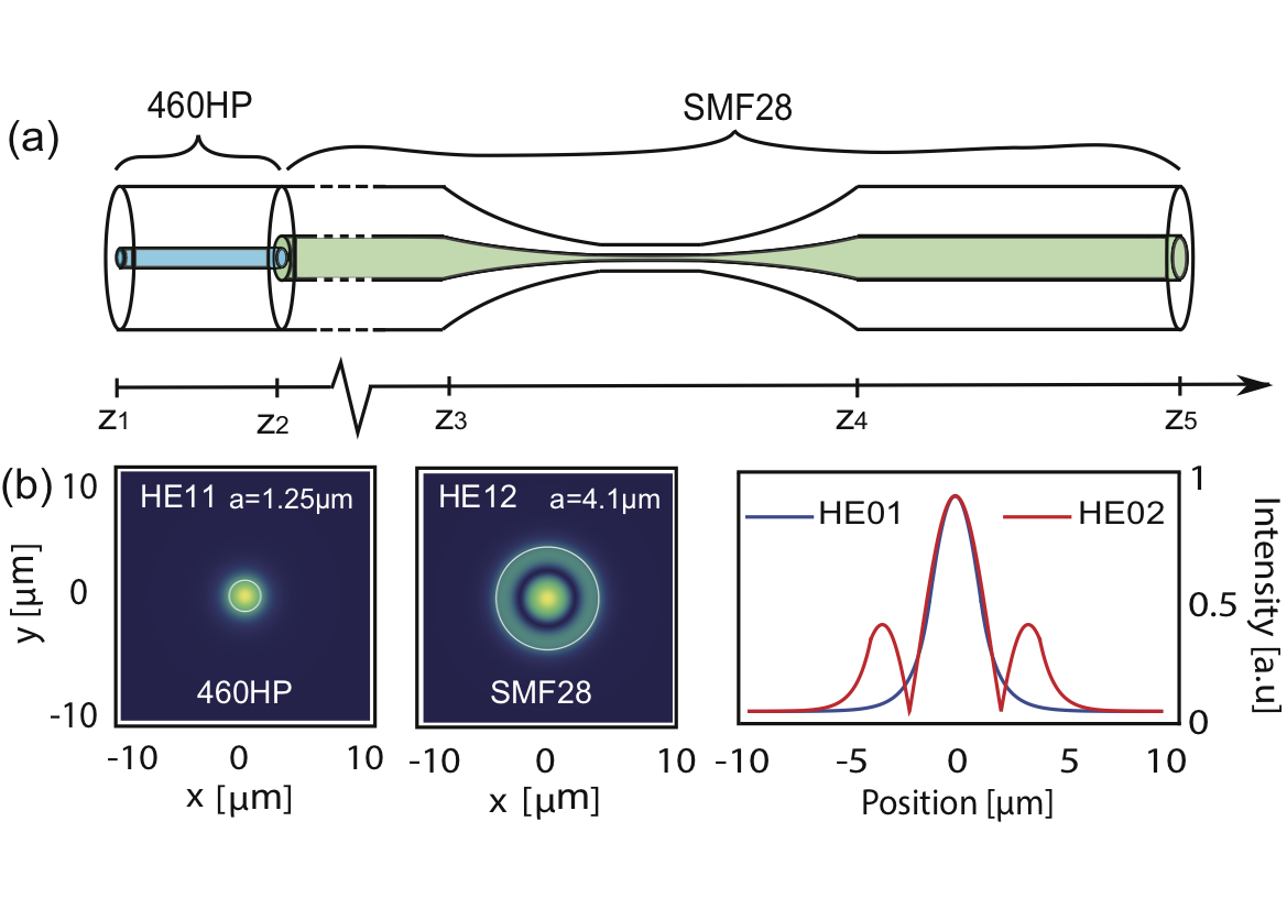
The concept that we exploit is that the fundamental mode HE11 at nm propagating in the 460HP fiber excites preferentially, upon arrival to the intra-fiber interface, the HE12 mode in the SMF28 fiber. This occurs because: i) the mode field diameter of the HE11 mode in the 460HP fiber is very similar to the diameter of the internal lobe of the HE12 mode in the SMF28 fiber, and ii) the effective index of refraction of the incoming HE11 mode and that of the excited HE12 mode are very similar, differing only by . In Fig. 11(b) we plot the simulated incoming HE11 mode, as well as the excited HE12 mode, along with a diametrical section of these two modes overlapped in a single plot making it clear that the modes are remarkably similar within the internal lobe. This leads to an unusually high mode overlap between the incoming and excited modes (at approximately the same level as the overlap between the fundamental modes in the two fibers). Note that the SMF28 can support higher-order modes but the overlap of these modes with HE11 from the 460HP drops dramatically.
In the SMF28, the presence of the HE11 and HE12 modes (transverse amplitudes and , and propagation constants and respectively) leads to a mode beating with a period . In Fig. 12 we show the evolution of the intensity pattern along the fiber resulting from the beating of the fundamental HE11 and higher-order mode HE12.
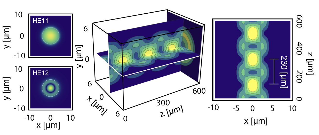
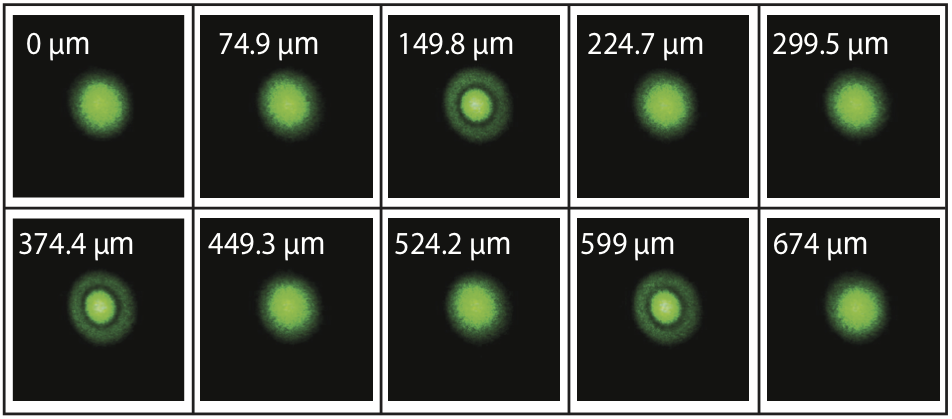
We fabricated a device as described above, with 460HP and SMF28 fibers spliced together. The SMF28 is then tapered down to m diameter. As the taper is made its length increases. During this process it is then possible to observe, in real time, the evolution of the beating pattern between the two modes involved as a function of length by monitoring the output of the device. Fig. 13 shows the evolution of the intensity of the near field at the output of the SMF28 as a function of the added length. This is consistent with the simulated beating period of m, confirming the considered approach.
| Fiber type | Peak pump power () | Seed wavelength [] | Peak seed power () | Inverse duty cycle | Detect. bandwidth () [nm] | Number of pairs (per pulse) |
| Hybrid core | W | 1.67 | W | 60 | ||
| Hollow-core | W | 1.605 | W | 200 | 0.5 | |
| Tapered | W | 1.6412 | W | 50 |
III.4 Seeding
Although seeding third-order parametric down-conversion reduces the generated state from a three-photon to a two-photon one, it does dramatically increase the emission rate probability. Whilst the hybrid and tapered fibers have measurable spontaneous three-photon emission rates, due to the poor overlap and low cubic susceptibility the hollow-core fiber does not (see Table. 1). Hence to observe any effect in the hollow-core fiber, stimulating one of the three photons is a necessity. Despite loosing the three-photon correlations, seeding can still lead to information about the spontaneous three-photon state using stimulated emission tomography. Moving to the seeded emission probabilities and subsequently the seeded emission rates it is clear that one can observe photon pairs for each fiber type. Here we assume a pulsed laser with a ps pulse duration and 1 kHz repetition rate, hence working with single-photon detectors the number of photons detected for the hybrid and tapered fibers would be limited by the repetition rate. In order to perform a proper correlation measurement, the pump or the seed power has to be reduced to generate less then a pair per pulse. The estimated conversion rates with seeding are given in Table 2.
IV Conclusion
We presented three different types of fibers and estimated their potential viability as platforms on which to generate photon triplet states via a direct cubic interaction. We checked this for both the spontaneous and seeded regime. The hybrid and tapered fibers proved to be the best fibers from which to observe photon triplets. However the former requires a tunable pump laser to satisfy phase matching due to its fixed geometry. Despite this drawback, the main advantage the hybrid fiber has over the other two designs is the ability to guide both the pump and triplets in a nearly Gaussian mode simultaneously. In contrast to the hybrid fiber, one can tune the phase matching in the the tapered fiber without changing the pump wavelength. This can be done by placing the tapered fiber into a gas under high tunable pressure. In addition, with the system we propose, it is possible to launch a high-order mode into the tapered fiber starting from a nearly Gaussian mode. Currently the design of the hollow-core fiber gives a very small conversion efficiency. However this can be improved by reducing the core size. By reducing the core diameter by only a factor of two, the conversion efficiency can be improved by around two orders of magnitude. In this case, a hollow-core fiber, with its high damage threshold and the pressure-dependent phase matching is a good candidate for seeding experiments.
References
- (1) H. Takesue and K. Inoue, “Generation of polarization-entangled photon pairs and violation of bell’s inequality using spontaneous four-wave mixing in a fiber loop,” Phys. Rev. A, vol. 70, p. 031802, Sep 2004.
- (2) J. G. Rarity, J. Fulconis, J. Duligall, W. J. Wadsworth, and P. S. J. Russell, “Photonic crystal fiber source of correlated photon pairs,” Opt. Express, vol. 13, pp. 534–544, Jan 2005.
- (3) X. Li, P. L. Voss, J. E. Sharping, and P. Kumar, “Optical-fiber source of polarization-entangled photons in the 1550 nm telecom band,” Phys. Rev. Lett., vol. 94, p. 053601, Feb 2005.
- (4) J. Fan, A. Migdall, and L. J. Wang, “Efficient generation of correlated photon pairs in a microstructure fiber,” Opt. Lett., vol. 30, pp. 3368–3370, Dec 2005.
- (5) S. L. Braunstein and R. I. McLachlan, “Generalized squeezing,” Phys. Rev. A, vol. 35, pp. 1659–1667, Feb 1987.
- (6) P. V. Elyutin and D. N. Klyshko, “Three-photon squeezing: exploding solutions and possible experiments,” Physics Letters A, 1990.
- (7) T. Felbinger, S. Schiller, and J. Mlynek, “Oscillation and generation of nonclassical states in three-photon down-conversion,” Phys. Rev. Lett., vol. 80, pp. 492–495, Jan 1998.
- (8) J. Douady and B. Boulanger, “Experimental demonstration of a pure third-order optical parametric downconversion process,” Opt. Lett., vol. 29, pp. 2794–2796, Dec 2004.
- (9) M. V. Chekhova, O. A. Ivanova, V. Berardi, and A. Garuccio, “Spectral properties of three-photon entangled states generated via three-photon parametric down-conversion in a medium,” Phys. Rev. A, vol. 72, p. 023818, Aug 2005.
- (10) F. Gravier and B. Boulanger, “Triple-photon generation: comparison between theory and experiment,” J. Opt. Soc. Am. B, vol. 25, pp. 98–102, Jan 2008.
- (11) M. Corona, K. Garay-Palmett, and A. B. U’Ren, “Experimental proposal for the generation of entangled photon triplets by third-order spontaneous parametric downconversion in optical fibers,” Opt. Lett., vol. 36, pp. 190–192, Jan 2011.
- (12) M. G. Moebius, F. Herrera, S. Griesse-Nascimento, O. Reshef, C. C. Evans, G. G. Guerreschi, A. Aspuru-Guzik, and E. Mazur, “Efficient photon triplet generation in integrated nanophotonic waveguides,” Opt. Express, vol. 24, pp. 9932–9954, May 2016.
- (13) A. Cavanna, F. Just, X. Jiang, G. Leuchs, M. V. Chekhova, P. S. Russell, and N. Y. Joly, “Hybrid photonic-crystal fiber for single-mode phase matched generation of third harmonic and photon triplets,” Optica, vol. 3, pp. 952–955, Sep 2016.
- (14) E. A. R. González, A. Borne, B. Boulanger, J. A. Levenson, and K. Bencheikh, “Continuous-variable triple-photon states quantum entanglement,” Phys. Rev. Lett., vol. 120, p. 043601, Jan 2018.
- (15) C. Chang, C. Sabín, P. Forn-Díaz, F. Quijandría, A. Vadiraj, I. Nsanzineza, G. Johansson, and C. Wilson, “Observation of three-photon spontaneous parametric downconversion in a superconducting parametric cavity,” arXiv preprint arXiv:1907.08692, 2019.
- (16) H. Huebel, D. R. Hamel, A. Fedrizzi, S. Ramelow, K. J. Resch, and T. Jennewein, “Direct generation of photon triplets using cascaded photon-pair sources,” Nature, 2010.
- (17) T. Guerreiro, A. Martin, B. Sanguinetti, J. S. Pelc, C. Langrock, M. M. Fejer, N. Gisin, H. Zbinden, N. Sangouard, and R. T. Thew, “Nonlinear interaction between single photons,” Phys. Rev. Lett., vol. 113, p. 173601, Oct 2014.
- (18) C. Okoth, A. Cavanna, N. Y. Joly, and M. V. Chekhova, “Seeded and unseeded high-order parametric down-conversion,” Phys. Rev. A, vol. 99, p. 043809, Apr 2019.
- (19) M. Liscidini and J. E. Sipe, “Stimulated emission tomography,” Phys. Rev. Lett., vol. 111, p. 193602, Nov 2013.
- (20) G. Agrawal, Nonlinear fiber optics. Academic Press, 2012.
- (21) are vectors but we omit vector notation for simplicity.
- (22) J. Hammer, A. Cavanna, R. Pennetta, M. V. Chekhova, P. S. Russell, and N. Y. Joly, “Dispersion tuning in sub-micron tapers for third-harmonic and photon triplet generation,” Opt. Lett., vol. 43, pp. 2320–2323, May 2018.
- (23) T. A. Birks, G. J. Pearce, and D. M. Bird, “Approximate band structure calculation for photonic bandgap fibres,” Opt. Express, vol. 14, pp. 9483–9490, Oct 2006.
- (24) A. Cavanna, F. Just, P. R. Sharapova, M. Taheri, G. Leuchs, and M. V. Chekhova, “Tunable optical parametric generator based on the pump spatial walk-off,” Opt. Lett., vol. 41, pp. 646–649, Feb 2016.
- (25) N. L. Boling, A. J. Glass, and A. Owyoung, “Empirical relationship for predicting nonlinear refractive index changes index changes in optical solids,” IEEE Journal of Quantum Electronics, vol. 14, no. 8, pp. 601–608, 1978.
- (26) C. Brée, A. Demircan, and G. Steinmeyer, “Method for computing the nonlinear refractive index via keldysh theory,” IEEE Journal of Quantum Electronics, vol. 46, no. 4, pp. 433–437, 2010.
- (27) A. D. Pryamikov, A. S. Biriukov, A. F. Kosolapov, V. G. Plotnichenko, S. L. Semjonov, and E. M. Dianov, “Demonstration of a waveguide regime for a silica hollow-core microstructured optical fiber with a negative curvature of the core boundary in the spectral region¿ 3.5 m,” Optics express, vol. 19, no. 2, pp. 1441–1448, 2011.
- (28) C. Wei, R. J. Weiblen, C. R. Menyuk, and J. Hu, “Negative curvature fibers,” Advances in Optics and Photonics, vol. 9, no. 3, pp. 504–561, 2017.
- (29) P. Uebel, M. C. Günendi, M. H. Frosz, G. Ahmed, N. N. Edavalath, J.-M. Ménard, and P. S. J. Russell, “Broadband robustly single-mode hollow-core pcf by resonant filtering of higher-order modes,” Optics letters, vol. 41, no. 9, pp. 1961–1964, 2016.
- (30) J. Nold, P. Hölzer, N. Y. Joly, G. K. L. Wong, A. Nazarkin, A. Podlipensky, M. Scharrer, and P. S. Russell, “Pressure-controlled phase matching to third harmonic in ar-filled hollow-core photonic crystal fiber,” Opt. Lett., vol. 35, pp. 2922–2924, Sep 2010.
- (31) J.-L. Archambault, R. J. Black, S. Lacroix, and J. Bures, “Loss calculations for antiresonant waveguides,” Journal of Lightwave Technology, vol. 11, no. 3, pp. 416–423, 1993.
- (32) M. Zeisberger and M. A. Schmidt, “Analytic model for the complex effective index of the leaky modes of tube-type anti-resonant hollow core fibers,” Scientific reports, vol. 7, no. 1, p. 11761, 2017.
- (33) H. J. Lehmeier, W. Leupacher, and A. Penzkofer, “Nonresonant third order hyperpolarizability of rare gases and n2 determined by third harmonic generation,” Optics Communications, vol. 56, no. 1, pp. 67–72, 1985.
- (34) T. Birks and Y. W. Li, “The shape of fiber tapers,” Journal of Lightwave Technology, vol. 10, pp. 432–438, 1992.
- (35) A. W. Snyder and J. Love, Optical Waveguide Theory. Springer Science & Business Media, 1983.
- (36) J. D. Love and W. M. Henry, “Quantifying loss minimisation in single-mode fibre tapers,” Electronics Letters, vol. 22, pp. 912–914, Aug. 1986.
V Appendix: Spectral density of three-photon emission
The expression for in Eq.18 can be simplified to a function of two variables by integrating over the delta function . Due to energy conservation this fixes the frequency of . Thus we can rewrite Eq.18 as
| (27) |
Plotting gives the spectral density of the three-photon emission.
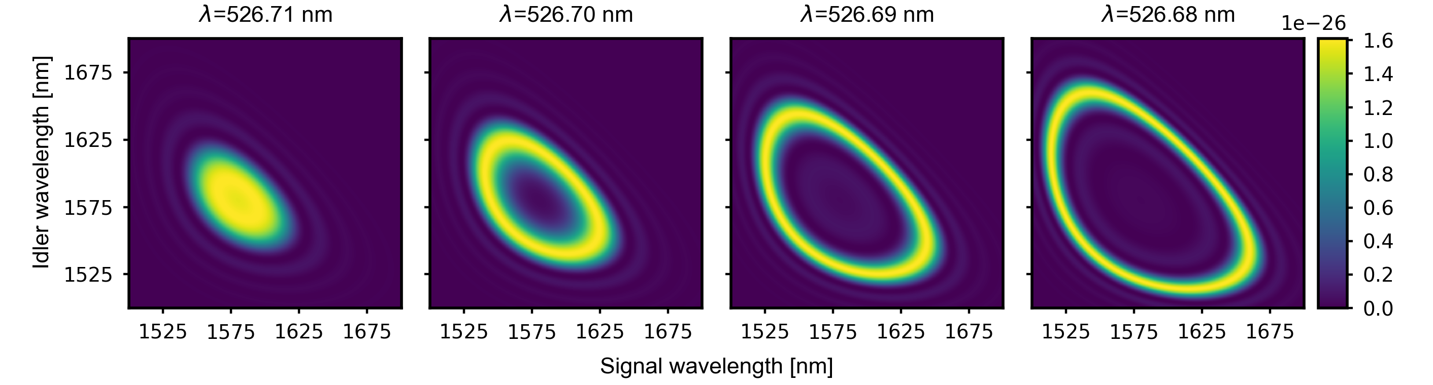
Figure 14 shows the spectral density for the hybrid fiber for the parameters shown in Table 1. Varying the pump wavelength by only 0.01 nm, one changes the spectral density vastly. This is due to the extremely different dispersion properties of the inner and outer core. In addition the spectral density is very broad, ranging over almost 150 nm. A combination of these two attributes makes it critical for the pump to be narrowband enough to minimize the collection bandwidth and increase the signal-to-noise ratio.
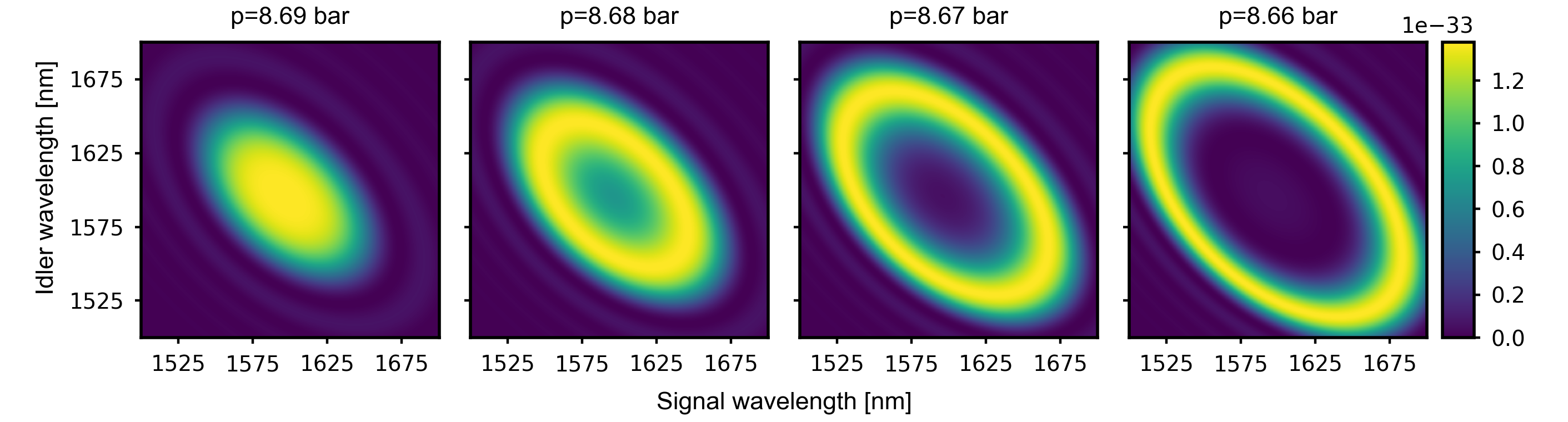
Figure 15 shows the spectral density for the hollow-core fiber filled with Xenon gas and pumped at 532 nm. By reducing the gas pressure it is possible to pass from degenerate to non-degenerate phase matching. Although the spectral width has a strong dependence on the pressure, this can be easily and precisely controlled with standard equipment.
Finally, in Fig. 16 the spectral density for the tapered fiber is shown. The tapered region is highly dispersive due to the high confinement and increasing mode leakage into the ambient environment at longer wavelengths. This leads to a very narrow emission bandwidth. Although it means that the phase matching is critical, it is an advantage to work with the narrow spectrum as it means that the full emission spectrum can be collected.