Intelligent Reflecting Surface Aided Multi-User mmWave Communications for Coverage Enhancement
Abstract
Intelligent reflecting surface (IRS) is envisioned as a promising solution for controlling radio propagation environments in future wireless systems. In this paper, we propose a distributed intelligent reflecting surface (IRS) assisted multi-user millimeter wave (mmWave) system, where IRSs are exploited to enhance the mmWave signal coverage when direct links between base station and users are unavailable. First, a joint active and passive beamforming problem is established for weighted sum-rate maximization. Then, an alternating iterative algorithm with closed-form expressions is proposed to tackle the challenging non-convex problem, thereby decoupling the active and passive beamforming variables. Moreover, we design a constraint relaxation technique to address the unit modulus constraints pertaining to the IRS. Numerical results demonstrate that the distributed IRS can potentially enhance the communication performance of existing wireless systems.
Index Terms:
Intelligent reflecting surface, millimeter wave, distributed IRS deployment, beamforming.I Introduction
The proliferation of applications and mobile traffic in fifth generation (5G) is driving the paradigm shift for wireless technologies, e.g., millimeter wave (mmWave) and massive multiple-input multiple-output (MIMO). However, providing the logical control of radio propagation remains as an unsettled challenge [1]. For the envisioned mmWave systems with unrivaled data rates [2], signals are highly susceptible to blocking, thus causing sparse and low-rank channel structures. To enhance the practical feasibility, such scheme as ultra-dense deployment [3] also brings high cost and interference issues.
Recently, intelligent reflecting surface (IRS), as an emerging concept, has great potential to cost-effectively improve the network performance in 5G and beyond. Unlike the active amplify-and-forward (AF) relay, IRS is composed of nearly passive reflecting elements, and thus it is low cost, low power, flexible, and scalable [4]. More importantly, the dynamic wireless environment can be turned into a partially deterministic space with the reconfiguration of the IRS.
The various IRS-aided wireless systems have been extensively studied. The reflect beamforming at the IRS is referred to as passive beamforming (PBF), while the precoding operation at the base station (BS) is termed as active beamforming (ABF). In [1], the ABF and PBF are jointly designed to reduce the transmit power while meeting the received signal-to-interference-plus-noise ratio (SINR) requirement for each user. Besides this, the future directions about the IRS deployment are also mentioned. In [5], the beamforming design problems are extended to the discrete-phase cases. Then, the authors of [6] investigate the IRS-aided physical-layer security. To study the suitability of IRS in terms of energy efficiency (EE), the authors of [4] propose EE maximization algorithms for the multiple-input single-output (MISO) scenario. Most studies assume the rich scattering between BS and IRS [7, 8], but the low-rank BS-IRS channel [1] should be considered when it comes to mmWave transmissions. Recently, the potential use of IRS is studied in [9] from a perspective of mmWave, where weak BS-user links were compensated by the reflection gain of the IRS.
However, the low-rank BS-IRS channel cannot support multi-user downlink transmissions when the BS-user links are unavailable due to the severe blockage. To conquer this issue, in this paper, we propose a distributed IRS (D-IRS) deployment solution to create higher-rank channels, and thus a smart radio environment created by multiple IRS units can achieve robust transmissions and reduce the signal blind spots. In the proposed D-IRS enhanced multi-user mmWave systems without direct links, we formulate the weighted sum-rate maximization (WSM) problem by jointly designing the ABF and PBF matrices. This problem with the non-convexity and coupled variables is generally difficult. To tackle this issue, we propose an alternating iterative method, where closed-form expressions are derived in each iteration. The non-convex unit-modulus constraints of the IRS constitute a great challenge of the PBF optimization. We thus devise a constraint relaxation approach to efficiently solve the PBF design. The effectiveness of our scheme is verified, and the impacts of network parameters on sum-rate performance are analyzed. The main contributions of our work are as follows:
-
•
For mmWave systems without direct links, a D-IRS deployment scheme is proposed to avoid low-rank BS-IRS mmWave channel. For one thing, this multi-IRS scenario breaks the constraint of rank-one channel, thus leading to high spatial multiplexing gain. For another, the smart radio environment created by multiple IRS units can achieve robust transmissions.
-
•
Based on the D-IRS enhanced multi-user mmWave system, we formulate the joint ABF and PBF design as a WSM problem. To tackle this non-convex problem, we propose an alternating iterative method, where closed-form expressions are derived in each iteration.
-
•
To tackle the unit modulus constraints, a constraint relaxation approach is devised. The performance of our scheme is evaluated, and the impact of the number of IRS elements as well as users on sum-rate performance is analyzed.
Notations: Lower-case and upper-case boldface letters denote vector and matrix, respectively; , , and represent the conjugate, the transpose, and the conjugate transpose; , and return the trace, vectorization and diagonalization; represents the -th entry of a matrix; ; and denote the real part and the phase of a complex value; and denote the Kronecker and Hadamard products, respectively.
II System Model
II-A IRS-assisted Downlink mmWave MIMO System
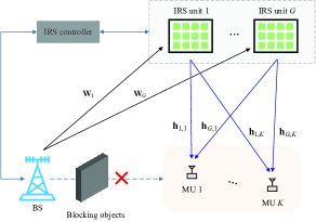
Fig. 1 shows an IRS-assisted downlink mmWave system, where a base station (BS) is equipped with a uniform linear array (ULA) composed of elements. There are IRS units serving single-antenna mobile users (MUs). Each IRS unit is assumed to be with elements horizontally and elements vertically. Let . The direct BS-user links are assumed to be blocked by obstacles. The BS can only communicate with the MUs via the reflection of the IRS. These IRS units are controlled by a smart controller, which coordinates the reflecting modes for all IRS units.
The received signal at the -th MU can be expressed as
| (1) |
where is the mmWave channel between BS and the -th IRS unit, and is the channel between the -th IRS unit and the -th MU; the phase shift matrix of the -th IRS unit is denoted by where is the reflection coefficient111Different from the backscatter communications, the incident signal energy is not absorbed to drive the circuit for IRS and thus we set . and with being the phase shift; is the transmit signal from BS for the -th MU with zero mean and normalized power, and is the noise which follows the circularly symmetric complex Gaussian (CSCG) distribution of ; is the precoding matrix222Undermined by mixed-signal processing and hardware constraints in practice, the hybrid precoding is a feasible scheme for the mmWave system. The subsequent hybrid precoding problem can be solved by the spatially sparse precoding [10]. However, this is out of the scope of current manuscript. where is used by BS to transmit signal . The total transmit power constraint at the BS is .
II-B Wireless Channel Model
According to the widely used 3D Saleh-Valenzuela channel model [11], can be expressed as
| (2) |
where denotes the number of non-line-of-sight (NLoS) paths, represents the line-of-sight (LoS) path, and is the complex gain of the -th path. Note that mmWave channels normally consist of only a small number of dominant multipath components [2, 3], while the scattering at sub-6 GHz is generally rich. Here, the elevation and azimuth angles for two-dimensional IRS are denoted by and . In (2), and are the array steering vectors of ULA and IRS. The array steering vectors and are defined in the same manner as , where is the wavelength, is the antenna spacing, and . The array element spacing of both ULA and IRS is assumed to be , and IRS is implemented with discrete antenna elements [12, 4], just like uniform rectangular array (URA).
Typically, the IRS is densely distributed in the hotspot spaces, which gives rise to a high probability of LoS path. Due to the severe path loss, the transmit power of 2 or more reflections can be ignored so that only LoS is considered [1, 5]. Thus, the channel between the -th IRS unit and the -th MU is given by
| (3) |
where is the channel gain; and are the receive and transmit antenna element gains, respectively; is the array steering vector of IRS. As typically considered in [1, 9, 4], all channels involved are assumed to be perfectly known in the paper.
III Joint Active and Passive Beamforming Design
III-A Problem Formulation and Transformation
We aim to maximize the downlink sum-rate of the proposed D-IRS assisted mmWave network by jointly optimizing the ABF and PBF matrices. The signal-to-interference-plus-noise ratio (SINR) of the -th MU is given by
| (4) |
The corresponding WSM problem can be formulated as
| (5a) | ||||
| s.t. | (5b) | |||
| (5c) | ||||
where is the weight assigned to the data of the -th MU, is the maximum transmit power, and the continuous-phase feasible set for is . Its discrete-phase counterpart is , where is the phase resolution in the number of bits.
Proposition 1
Proof:
See Appendix A. ∎
III-B Active Beamforming Scheme
We start with the ABF when given the PBF matrix set . For notational brevity, we define
| (8) |
Substituting (8) into (4), we reformulate as
| (9) | ||||
| s.t. |
where . We note that (9) is a multi-ratio fractional programming problem. By using the quadratic transform (QT) technique [13], we reformulate as
| (10) |
where is the auxiliary vector introduced by the use of QT, and (10) is a biconvex optimization problem. By setting , the optimal for a given is given by
| (11) |
Since Problem (10) is a convex problem with respect to , the optimal can be obtained by the Lagrangian multiplier method. Thus, the optimal for a given is
| (12) |
where is the Lagrange multiplier for the power constraint (5b). According to the following lemma, we can obtain the optimal via the bisection search method.
Lemma 1
The optimal value of in (12) is
| (13) |
Proof:
See Appendix B. ∎
III-C Passive Beamforming Scheme
After the completion of ABF, we continue to solve the PBF problem pertaining to the IRS. With mathematical manipulations, (8) can be rewritten as
| (14) |
where . For notational brevity, we define . Given and , we rewrite Problem (9) as
| (15a) | ||||
| s.t. | (15b) | |||
To facilitate the subsequent derivations, we first construct
| (16) | ||||
| (17) |
Then, can be reformulated as
| (18) |
where and . The corresponding QT of (18) is given by
| (19) |
where is the auxiliary vector introduced by the QT. Based on the Lagrange multiplier method, the optimal is given by
| (20) |
Given , the optimization of can be written as
| (21) |
where and . We can see that (21) is a quadratical constraint quadratic programming (QCQP) problem.
The IRS phase shift constraint (5c) is non-convex. We propose a constraint relaxation technique to address this unit-modulus constraint. Specifically, we replace (15b) with to convexity the constraint. By dropping the constant terms, we can rewrite (21) as
| (22a) | ||||
| s.t. | (22b) | |||
where . Problem (22) is a convex optimization problem. Accordingly, we can resort to the Lagrangian dual decomposition method to solve (22), since the strong duality holds. The Lagrange dual of (22) can be written as
| (23a) | ||||
| s.t. | (23b) | |||
In (23a),
| (24) |
where is the elementary vector with one in the -th position and zeros elsewhere; collects the dual variables associated with constraint (22b).
By setting , the optimal can be obtained as
| (25) |
where . The optimal value of is given in the following lemma.
Lemma 2
The optimal value of in (25) can be determined by
| (26) |
which indicates that the solution attained by the constraint relaxation-based method can guarantee that the unit-modulus constraints are satisfied.
Proof:
See Appendix C. ∎
Substituting (25) into (23) yields
| (27) |
In other words, (23) can be recast as a semi-definite programming (SDP) problem using the Schur complement:
| (28a) | ||||
| s.t. | (28b) | |||
which can be solved efficiently by using standard CVX toolboxes.
Furthermore, we can leverage the quantized phase projection method [7] to discretize the solutions. The proposed alternating iterative framework to solve Problem (6) is provided in Algorithm 1. To illustrate the convergence of the alternating iterative approach, we provide the following proposition.
Proposition 2
The problem in (6) converges when the alternating iterative algorithm is used.
Proof:
See Appendix D. ∎
IV Numerical Results
Without loss of generality, the weights are set to be equal in all the simulations. According to [9] and [11], the channel gain is taken as where with 333The distance between transmitter and receiver is denoted as , which can be calculated according to the simulated system layout.. The channel realizations are produced by setting dBm, dBi, dBi, , , and dB. The BS with antennas is located at the origin and the MUs are uniformly and randomly distributed in an circle centered at with radius . Here, we consider IRS units located at and . Unless otherwise stated, the total transmit power is set to dBm [9].
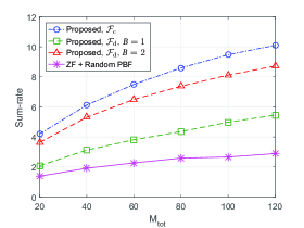
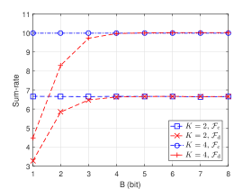
Fig. 2 shows the sum-rate versus the number of reflecting elements where and increases from 1 to 6. Zero-forcing (ZF) precoding with a random PBF method is simulated as the baseline. Clearly, the proposed algorithm outperforms the baseline method in terms of sum-rate. The sum-rate increases, as increases from 20 to 120. Moreover, the proposed algorithm with 1-bit phase shifters at the IRS can consistently outperform the baseline method, and the gain becomes significant when 2-bit phase shifters are adopted.
To investigate the phase resolution of IRS required to archive acceptable system performance, Fig. 3 shows the performance gap between phase-shifter of infinite resolution and that of various quantization bits. Each IRS unit size is set as and . It is observed that the sum-rate performance gap gradually decreases with increasing from 1 bit to 8 bits. When , the performance gap can reach 0.17 and 0.26 for 2-user case and 4-user case, respectively. We conclude that only 4-bit phase shifter can achieve the equivalent performance gain as continuous phase.
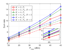
Fig. 4 assesses the impact of the transmit power on the sum-rate of our proposed algorithm. We set and . The red, green and blue lines indicate the 2-user, 4-user, and 6-user scenarios, respectively. As depicted in the figure, with the transmit power increasing from 20 dBm to 45 dBm, all of the multi-user cases exhibit the same upward trend. As the number of users grows in the network, the sum-rate attained under the infinite resolution elements and the same transmit power also increases. The tendency of 2-bit resolution case is consistent with that of the infinite resolution case.
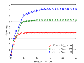
Fig. 5 shows the convergence trend of the proposed alternating iterative algorithm. The convergence of our proposed algorithm is confirmed in multiple simulated cases. When and , our proposed method converges after about 5 iterations. As the number of users or the value of increases, we can see the convergent sum-rate of the proposed algorithm grows. To conclude, the proposed algorithm can achieve fast convergence.
V Conclusion
To support multi-user transmission in the mmWave blind spots, a distributed deployment of IRS units was introduced to create the high-rank mmWave channels. In this paper, an alternating iterative algorithm was designed to maximize the weighted sum-rate of the IRS-aided mmWave systems. The algorithm jointly optimizes ABF and PBF with closed-form solutions at each iteration. Simulation results corroborated the feasibility and effectiveness of the proposed scheme.
Appendix A Proof of Proposition 1
Note that is a concave differentiable function with respect to when given . Thus, setting to zero yields . Based on this fundamental result, substituting back in the objective function of (5) can be recast to (6). As such, the optimal objective values of these two problems are equal and their equivalence is established.
Appendix B Proof of Lemma 1
Appendix C Proof of Lemma 2
Using the chain rule in matrix differentiation, we have
| (31) |
Setting (31) to zero yields
| (32) |
This completes our proof.
Appendix D Proof of Proposition 2
References
- [1] Q. Wu and R. Zhang, “Intelligent reflecting surface enhanced wireless network via joint active and passive beamforming,” IEEE Trans. Wireless Commun., pp. 1–1, Aug. 2019.
- [2] A. Alkhateeb, O. El Ayach, G. Leus, and R. W. Heath, “Channel estimation and hybrid precoding for millimeter wave cellular systems,” IEEE J. Sel. Topics Signal Process., vol. 8, no. 5, pp. 831–846, Oct. 2014.
- [3] Z. Gao, L. Dai, D. Mi, Z. Wang, M. A. Imran et al., “MmWave massive-MIMO-based wireless backhaul for the 5G ultra-dense network,” IEEE Wireless Commun., vol. 22, no. 5, pp. 13–21, Oct. 2015.
- [4] C. Huang, A. Zappone, G. C. Alexandropoulos, M. Debbah, and C. Yuen, “Reconfigurable intelligent surfaces for energy efficiency in wireless communication,” IEEE Trans. Wireless Commun., vol. 18, no. 8, pp. 4157–4170, Aug. 2019.
- [5] Q. Wu and R. Zhang, “Beamforming optimization for intelligent reflecting surface with discrete phase shifts,” in Proc. IEEE Int. Conf. Acoust., Speech Signal Process. (ICASSP), Brighton, United Kingdom, May 2019, pp. 7830–7833.
- [6] M. Cui, G. Zhang, and R. Zhang, “Secure wireless communication via intelligent reflecting surface,” IEEE Wireless Commun. Lett., pp. 1–1, May 2019.
- [7] H. Guo, Y. Liang, J. Chen, and E. G. Larsson, “Weighted sum-rate maximization for reconfigurable intelligent surface aided wireless networks,” IEEE Trans. Wireless Commun., pp. 1–1, 2020.
- [8] Y. Han, W. Tang, S. Jin, C. Wen, and X. Ma, “Large intelligent surface-assisted wireless communication exploiting statistical CSI,” IEEE Trans. Veh. Technol., vol. 68, no. 8, pp. 8238–8242, Aug. 2019.
- [9] P. Wang, J. Fang, X. Yuan, Z. Chen, H. Duan et al., “Intelligent reflecting surface-assisted millimeter wave communications: Joint active and passive precoding design,” arXiv preprint arXiv:1908.10734, 2019.
- [10] O. E. Ayach, S. Rajagopal, S. Abu-Surra, Z. Pi, and R. W. Heath, “Spatially sparse precoding in millimeter wave MIMO systems,” IEEE Trans. Wireless Commun., vol. 13, no. 3, pp. 1499–1513, Mar. 2014.
- [11] M. R. Akdeniz, Y. Liu, M. K. Samimi, S. Sun, S. Rangan et al., “Millimeter wave channel modeling and cellular capacity evaluation,” IEEE J. Sel. Areas Commun., vol. 32, no. 6, pp. 1164–1179, Jun. 2014.
- [12] S. Hu, K. Chitti, F. Rusek, and O. Edfors, “User assignment with distributed large intelligent surface (LIS) systems,” in Proc. IEEE Annu. Int. Symp. Pers., Indoor, Mobile Radio Commun. (PIMRC), Bologna, Italy, Sep. 2018, pp. 1–6.
- [13] K. Shen and W. Yu, “Fractional programming for communication systems-part I: Power control and beamforming,” IEEE Trans. Signal Process., vol. 66, no. 10, pp. 2616–2630, May 2018.