∎
22email: h.bride@griffith.edu.au 33institutetext: Jin Song Dong 44institutetext: National University of Singapore
Griffith University
44email: j.dong@griffith.edu.au 55institutetext: Ryan Green 66institutetext: Defence Science and Technology Group, Australia
University of South Australia
66email: ryan.green@adelaide.edu.au 77institutetext: Zhé Hóu 88institutetext: Griffith University
88email: z.hou@griffith.edu.au 99institutetext: Brendan Mahony 1010institutetext: Defence Science and Technology Group, Australia
1010email: Brendan.Mahony@dst.defence.gov.au 1111institutetext: Martin Oxenham 1212institutetext: Defence Science and Technology Group, Australia
1212email: Martin.Oxenham@dst.defence.gov.au
GRAVITAS: A Model Checking Based Planning and Goal Reasoning Framework for Autonomous Systems
Abstract
While AI techniques have found many successful applications in autonomous systems, many of them permit behaviours that are difficult to interpret and may lead to uncertain results. We follow the “verification as planning” paradigm and propose to use model checking techniques to solve planning and goal reasoning problems for autonomous systems. We give a new formulation of Goal Task Network (GTN) that is tailored for our model checking based framework. We then provide a systematic method that models GTNs in the model checker Process Analysis Toolkit (PAT). We present our planning and goal reasoning system as a framework called Goal Reasoning And Verification for Independent Trusted Autonomous Systems (GRAVITAS) and discuss how it helps provide trustworthy plans in an uncertain environment. Finally, we demonstrate the proposed ideas in an experiment that simulates a survey mission performed by the REMUS-100 autonomous underwater vehicle.
1 Introduction
Planning is a central and hard Artificial Intelligence problem that is essential in the development of autonomous systems. Many existing solutions require a controlled environment in order to function correctly and reliably. However, there are situations where adaptive autonomous systems are required to run for a long period of time and cope with uncertain events during the deployment. Our work is motivated by the requirements of next generation autonomous underwater vehicles (AUV) in law enforcement and defence industries. Particularly, we are currently developing a decision making system which is suitable for an AUV designed to stay underwater for a long time and to have very limited communication with the outside world. The AUV is expected to carry out survey missions on its own and report details of its surveillance at semi-regular intervals. During the mission, the AUV may encounter underwater currents, deep ocean terrain, fishing boats, objects and places of interest, hostile vehicles etc., each of which may affect its ability to achieve its goals. The AUV must be able to decide which goals to pursue when such dynamic events occur and plan tasks to achieve the goals in an agile manner.
When there are uncertainties in the environment, planning becomes an even harder problem. In this case, the agent’s goal may be affected, thus both selecting a new goal and re-planning are necessary. This generally follows a note-assess-guide procedure, where note detects discrepancies (e.g., PCP13 ), assess hypothesises causes for discrepancies, and guide performs a suitable response AOC06 . Differing from classical planning where the goal is fixed, when a discrepancy is detected, it is often necessary to change the current goal. Goal reasoning is about selecting a suitable goal for the planning process. There have been various formalisms that attempt to solve planning problems in a dynamic environment, including hierarchical planning methods, such as hierarchical task networks (HTN) erol1994umcp and hierarchical goal networks (HGN) shivashankar2012hierarchical , and goal reasoning systems such as the Metacognitive Integrated Dual-Cycle Architecture (MIDCA) Cox2016 and the goal lifecycle model RobertsAJAWA15 ; Johnson2016 .
Although some of the above formalisms have been successfully applied to solve real life problems, the verification aspect of the problem remains to be addressed. Usually, planning is solved by heuristic search, but heuristics may miss some cases and produce sub-optimal or even undesired results. The correctness, safety, and security issues of autonomous systems are particularly important in mission-critical use cases. To tackle this problem, we turn to formal methods, which have been used to solve planning problems in the literature. For example, Giunchiglia et al. proposed to solve planning problems using model checking giunchiglia1999planning ; Kress-Gazit et al.’s framework translates high-level tasks defined in linear temporal logic (LTL) Pnueli1977 to hybrid controllers KressGazit2009 ; Bensalem et al. bensalem2014verification used verification and validation (V&V) methods to solve planning.
Following the above ideas, we propose a model checking based framework for hierarchical planning and goal reasoning. Model checking is a technique that can automatically verify whether certain properties are satisfied in a model using exhaustive search. Model checking is especially strong in addressing uncertain and concurrent behaviours. It has been successfully applied to modelling and verification of uncertain environments such as network attacks which may involve arbitrary behaviour in communication protocols bai2013authscan . We choose to use the model checker Process Analysis Toolkit (PAT) SLD09 – a self-contained tool that supports composing, simulating and reasoning about concurrent, probabilistic and timed systems with non-deterministic behaviours. Besides, we choose PAT because its verification outcome includes a witness trace which can be effectively extracted to form a plan.
Since our planning method is realised in PAT, we can formulate inconsistency and incompatibility of plans and goals as reachability and LTL properties clarke1986automatic , and verify them at execution time. For instance, when a new goal is generated during execution, we can check whether the new goal conflicts with existing goals, and select a subset of goals that are compatible with each other. In addition, we can also verify the planning model itself such that a given planning model does not output plans that may lead to undesired events. Based on the use of PAT, we propose a novel planning and goal reasoning system called Goal Reasoning And Verification for Independent Trusted Autonomous Systems (GRAVITAS) – a framework in charge of producing and actuating verifiable and explainable plans for autonomous systems. We demonstrate the proposed techniques in a simulation environment which is compatible with modern AUVs.
2 Preliminaries
Model checking Clarke2000 is an automated technique for formally verifying finite-state systems. In model checking, specifications of finite-states systems, i.e., properties to be verified, are often expressed in temporal logic whereas the system to be checked is modelled as a state transition graphs. Model checking involves a search procedure which is used to determine whether the model can reach a state that satisfies the specifications. We briefly introduce the modelling language and the specification language in PAT below.
Modelling language.
Models that can be verified using PAT SLD09 may take several forms, including: CSP# models, timed automata, real-time models and probabilistic models. The latter ones are extensions of the CSP# language. In this paper, all the examples only use CSP# – a high-level modelling language that extends Tony Hoare’s Communicating Sequential Processes hoare1978communicating with C#. Formally, a CSP# model is a tuple where is a finite set of global variables, is the initial valuation of global variables, and is a process. Variables are typed: either by a pre-defined type (e.g., boolean, integer, array) or by any user-defined data type. If the type of a variable is not explicitly stated, then, by default, the variable is assumed to be an integer. For instance, an integer variable and an integer array can be defined respectively as follows:
The range of a variable can be specified in the definition. For instance, the annotation ‘’ specifies that the value of each element in must be in the close interval . The three values of are initialised as s, as denoted by right-hand side of ’s declaration – i.e., is equivalent to .
A CSP# process is defined using the following syntax:
where is the process name, are the optional parameters of the process, and is a process expression, which defines the computation of the process. The running example in this paper uses the following subset of CSP#, shown in Backus–Naur form:
Interested readers can refer to Sun et al.’s paper sun2008 for the complete syntax and semantics of CSP#. The process terminate the execution of a process. The process does nothing. Let P and Q be CSP# processes. The process expression first activates the event labelled by and executes the statements given by , then it proceeds with the execution of . The statements of are defined by the syntax and semantics of C# and can therefore manipulate complex data types. The processes and respectively express the sequential and parallel composition of processes and . We use to state that either or may execute, depending on which one performs an event first. On the other hand, non-deterministically executes either or . The expression is self-explanatory. Finally, the expression , where is a boolean expression, defines a guarded process such that only executes when is satisfied.
Specification language.
We can check whether a CSP# process satisfies a given specification using the following expression:
where can be (the process does progress until reaching a terminating state), (the process performs internal transitions forever without engaging any useful events), (the process does not involve non-deterministic choices), and (no terminating states can be reached).
Also, we can check whether the transition system can reach a state where a boolean expression is satisfied using:
Additionally, we can check whether a process satisfies a LTL (cf. Huth et al.’s book (Huth2004, , Section 3.2.1)) formula using:
PAT output.
When checking LTL properties, PAT produces a counter-example when the property to be checked cannot be satisfied, and only outputs “yes” when when the property can be satisfied. For reachability properties, which are widely-used in the planning technique of this paper, PAT outputs different information. When the desired states cannot be reached, PAT outputs “no”. When the desired states can be reached, PAT produces a witness trace of actions that leads to the desired states. When model checking reachability properties, the user can specify one of the following verification engines: If a breath-first search based engine is used and the desired states can be reached, then PAT will output the shortest witness trace, which is useful when finding certain “optimal” plans. Furthermore, the user can tell PAT to output the witness trace that optimises certain criterion. For example, the following code will produce witness traces that respectively yield maximum reward and minimum penalty, assuming that is reachable and and are predefined variables:
3 Motivating Example
Surveying underwater areas and reporting back the locations of potential objects of interest are important usages of AUVs. For instance, in the search for the missing aircraft from Malaysia Airlines Flight 370, AUVs were deployed in deep ocean areas to locate debris of the aircraft mh370search . There are also demands and interests from the defence industry to demonstrate the abilities to scan underwater areas for naval mines and dumped arms, as shown in the Wizard of Aus Autonomous Warrior Trial wizardofaus2018 .
In this paper we run an example with the following context that demonstrates a common survey mission for the AUV: the AUV is to be deployed at the initial position and to be recovered at the final position. During the mission, the AUV is expected to scan two survey areas and record the locations of objects of interest upon identification. Although our technique is general and could be used on all forms of AUVs and UAVs, we specifically target a torpedo-shaped AUV named REMUS-100 remus100 , which is equipped with side scanners that are able to detect surrounding objects. The side scanners have a scan range of about 15 meters and therefore, in order to cover large area, the AUV should perform a lawn mowing pattern so that the survey area is fully covered. The overall mission is visualised in Figure 1.
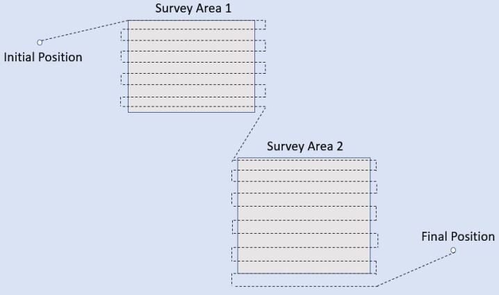
To deal with uncertainties of the environment, such as changes of survey areas, unexpected events during the transit from one location to another, our technique must be agile enough to accommodate the dynamics of the environment. The AUV also needs to make smart decisions autonomously, these include the order in which to visit the survey areas and the entry and exit point of each survey area that maximize trajectory efficiency.
4 Planning and Goal Reasoning via PAT
This section discusses how to solve Goal Task Network planning problems using model checking. We first give a new formalism of the GTN that is suitable for modelling in CSP #. We then propose a model checking based approach to model GTN and solve the planning problem. We also discuss how goal selection – a vital aspect of goal reasoning – can be done in this approach.
4.1 Goal Task Networks
Goal task networks (GTNs) are an extension and unification of hierarchical task networks and hierarchical goal networks Shivishankarthesis ; ASR16 . The main conceptual advantage of hierarchical task networks (HTNs), when compared to flat-structured task networks, is their ability to describe dependencies among actions in the form of nested task networks. HTNs have an explicit task hierarchy which generally reflects the hierarchical structure of many real-world planning applications. This hierarchy has decomposition methods which can then be used during the planning phase following the well known divide and conquer scheme. Due to this, HTNs planners are much more scalable and performant than classical planners in practice if the hierarchy is well-designed.
Goal task networks of Alford et al. ASR16 are similar to hierarchical task networks but also consider goals and sub-goals in addition to tasks and sub-tasks. As a result, they inherit the advantages of HTNs but also provide flexibility and reasoning capabilities in goal reasoning. We give an adaptation of the original GTN below with a focus on guarded state transitions, which are in the same form as processes in CSP#.
Let be a finite set of variables. Without loss of generality, the state of a goal task network over is defined as a function assigning a non-negative integer to each variable of . The set of goal task networks is recursively defined as where:
-
•
is a finite set of sub-tasks/goals,
-
•
is the guard associated with , and
-
•
is the state transition function associated with .
Let be a goal task network. Then can conceptually represent a task or a goal. In the sequel we shall loosely refer to as a task or a goal when the context is clear. When is a task, its guard models the conditions necessary for the task to begin. When is a goal, its guard models the conditions under which the goal is achieved.
Goal task networks whose set of sub-tasks/goals is empty are called primitive tasks/goals and describe the elementary block of goal task network executions.
The state of a goal task network evolves during its execution according to the following firing rules: A task/goal is enabled in state if and only if . A task/goal enabled in state can be fired, when it does so, it leads to a new state .
If is a primitive task/goal then denote the fact that is enabled in state and that its firing leads to state . If is not a primitive task/goal then denote the fact that there exists a valid execution of starting in state and leading to state .
Given an initial state , a valid execution of is a sequence , of tasks/ goals, where , such that and . The set of all valid execution starting from a given state is denoted by .
A GTN planning problem is tuple where is goal task network and is the initial state of . The set of solutions for is the the set of all valid plans , i.e., the set of all valid executions of starting in state .
A formalised model of our GTN definitions in Isabelle/HOL is available online 111https://figshare.com/articles/GTN_thy/6964394. The following theorem establishes that our GTN formalism can be used to represent the GTN of Alford et al ASR16 . The other direction is not important in the discussion of this paper.
Theorem 4.1
Given a GTN in Alford et al.’s notation ASR16 where is the set of goals and tasks, is a preorder between goals and tasks, and is a set of labels/names of goal/task instances, there is a corresponding GTN in the above definition.
4.2 Translating GTN Into CSP#
Let and be GTNs defined over the set of variables . Further, let be the initial state of . The GTN planning problem is modelled as follows.
First, the variables are declared and initialised to their initial values.
Second, the GTN and its sub-GTNs, as well as their sub-GTNs, are recursively defined using to the following template.
The process is guarded by the boolean predicate and, if executed, transforms the current state into its successor state according to the state transition . Note that can be effectively encoded by the set of C# statements as C# is Turing complete. Further, the process models the set of ’s sub-GTNs that can be executed before executing . In , we use non-deterministic choices to connect the execution of sub-GTNs. The last part of , i.e., , allows the process to repeat zero or more times, which effectively chooses and executes any sub-GTN zero or more times. This general translation allows the execution of GTN to be decomposed to the execution of any subset of sub-GTNs for any number of times. Finally, the CSP# process links the processes and to model the behaviour of the GTN .
Theorem 4.2
For every GTN , there is a corresponding model in CSP#.
Proof
(Sketch) By the construction of the CSP# process and according to the definition of the GTN , all valid transition sequences of the CSP# process correspond to valid plans of the GTN planning problem . ∎
Example
Take the overall control of the AUV survey mission as an example. At this granularity, the GTN is responsible for making high-level decisions regarding the mission, such as which survey area to visit, in which order, and how to visit it (enter from which direction and exit from which direction). Assuming all the predefined locations are stored in an array, a primitive task at this level is goto(i), which moves the AUV to location i:
In the task, the vector records the status of each location. The precondition ensures that each location is visited only once. Since is a primitive task, it does not contain subtasks/subgoals, therefore, its formulation only involves the guard condition and the transition.
The compound task dictates which locations to visit for survey area . This task does not have explicit state transitions, but instead performs state transitions in its subtasks ( tasks). Following the translation template, is formulated as:
where are the indices of the locations in survey area .
Similarly, the survey mission is formulated as below:
where are the indices for survey areas.
The overall GTN involves initialising the start position of the AUV, performing the survey mission, and returning to the final position for recovery. This is modelled as below where we omit the code of :
However, since the motivating example specifies that the three sub-GTNs of should be executed sequentially, the above definition can be optimised as below:
4.3 Planning Under Resource Constraints
For most planning applications, considering resource constraints, such as limited amount of available energy, is critical to the quality and relevance of the produced plan. This is particularly true in the application domain we consider as strategic commanders aim at launching AUVs that are meant to operate autonomously for extended period of time with limited resources. Therefore, it is essential that these resource constraints are correctly modelled in order to be able to produce plans that can be fully realised, i.e., plans that do not require more resources than available. Also, as unexpected events may arise during the execution of plans, it is necessary to formulate plans that minimise resource consumption in order to maximise the AUV’s resilience.
Suppose we wish to consider a finite set of resources and certain tasks that may consume or produce a finite and discrete amount of one or several of these resources. To do so we introduce, to the GTN modelling of a planning problem, a set of new variables modelling the amount of available resources. In the initial state, the values of these variables correspond to the amount of resources available on launch. When a tasks consumes one or several resources, its guard is extended so that it can only be executed if the resources needed to perform it are available before it executes. Additionally, its state transition function is also extended so that it decreases the values of the resource variables in order to reflect the resources consumed. Similarly, when a tasks produces one of several resources, its state transition function is extended so that it increases the values of the resource variables in order to reflect the resources produced.
Example
In the motivating example, we wish to model the AUV energy consumption while moving based on the distance to travel. To do so we introduce the variable energyLevel which models the amount of energy left in the battery as well as a function dist that returns the distance of the trajectory between two positions and the constant energyRequiredByMeter which is used to scale the energy consumption linearly with respect to a travelled distance. We then modify the implementation as follows:
These changes allow the states of the GTN modelling of a planning problem to encompass available resource quantities and guarantee that valid plans do not, at any time, consume more resources than available. Furthermore, these changes also enable us to minimise resource consumption by maximising the available resource quantities. However, as several resources may be considered, this leads to a multi-objectives optimisation problem that is unfortunately not readily supported by PAT.
We solve this problem by modelling the connections between resources. Note that some resources might be more valuable than others with respect to the mission objectives. Therefore, to avoid the need for multi-objectives optimisation capability, we propose to reduce the problem to a single-objective optimisation. To do so, we suggest the use of an extra variable acting as a common currency which is used, among other things, to evaluate the overall state of resources. To update the value of we require, for each resource , a conversion function relating the basic unit of a resource as modelled by variable to the basic unit of value of . Conversion functions used in practice include linear functions, logistic functions as well as exponential and logarithmic functions depending on the nature of the resources. Using these conversion functions, we further extend the state transition functions of tasks producing (respectively consuming) resources so that they increase (respectively decrease) the value of accordingly. An important aspect of this approach is that it enables the comparison of any two sets of quantified resources by transitivity. As a result, maximising the value of minimises the overall resources consumption while accounting for the relative importance of the considered resources. Another important aspect of this approach is that it provides mission operatives with an economic perspective on the complex relations that govern the relative importance of available resources – a familiar perspective people can relate to in everyday life.
To illustrate the use of a conversion function we integrate the common currency into the motivating example by inserting the following line after line 3 of the above code modelling the movement of the AUV, where and are user-defined constant:
Continuing with the AUV survey mission example, our model described above already takes the energy cost into account. To find a plan for the modelled GTN with respect to the energy cost, we first need to define the condition for the overall goal:
which states that all the locations are visited, and the AUV’s current location is the final position. We then use PAT to find a plan that yields minimal energy cost by model checking the following assertion:
4.4 Goal Reasoning
In this section we further discuss the concepts that enable our model checking based approach to deal with run-time goal reasoning.
4.4.1 Reasoning About Rewards/Penalties of Goals
Due to environment constraints and resource constraints, the completion of one or several goals may not be possible, or perhaps not worthwhile. Further, goals may not have the same priority. Some goals may be more important to the success of the mission than others. Additionally, as one of the underlying directives is to minimise resources consumption, the produced plans may not consider secondary objectives and only fulfil the minimum requirements in order to complete the mission if the incentive to do so is not correctly modelled.
To cope with these challenges, we propose to associate the achievement of a goal with a reward function relating the goal completion to an amount of the basic unit of value of – the previously introduced variable acting as the common currency. In this setting, maximising the value of prioritises and incentivises the completion of goals providing the most rewards while compromising with the resources they require to be completed. Further, as the resources conversion functions and the reward functions can be arbitrarily complex arithmetic functions, this provides a way to assess trade-offs between complex, competing criteria for a large number of resources and goals.
These economic notions therefore lead to the formulation of highly cost-effective plan. Additionally, when multi-agents missions are considered, they provide further benefits as market-based mechanisms clearwater1996market can be leveraged to obtain greater collaboration among agents as well as to optimise resources and tasks allocation. These mechanisms also provide non-technical operatives the means to leverage their day to day economic knowledge to specify technical details of the missions that have to be accomplished by the agent.
Example
Returning to the motivating example, we wish to prioritise the recovery of the vehicle () over the completion of the survey (). To achieve this, we first insert the following code into (between the curly braces):
We then modify the definition of :
We set to be far greater than where is the total number of positions in the model. We also have to ensure that is greater than * , otherwise PAT will choose not to visit any position at all. Finally, we modify the so that visiting all positions and returning to recovery position is no longer mandatory. Rather, we use a more flexible goal, defined as below:
where is a subset of positions that are critical and will override the optimisation on reward/penalty. Now when we model check
If the is sufficient to visit all positions and go to the recover position, then PAT will output such a plan with minimal energy consumption. Otherwise, if the is insufficient due to unexpected events such as strong current, energy spent on detour or surveying uncertain objects, etc., PAT will try to find a plan that ensures that the positions in are visited, and that is far more likely to be executed than visiting a few more positions.
4.4.2 Reasoning About Consistency of Goals
Consider the following scenario: the AUV has finished the survey mission and now has to report the results. There are two ways to report: (1) acoustic communication with a nearby friendly surface vessel; (2) surface and use satellite communication. Suppose there is no friendly surface vessel nearby, then the AUV will choose the second method. However, suppose there is a hostile surface vessel, which the AUV should avoid. Now the AUV has two goals: report using satellite communication and avoid the hostile surface vessel. The underlying plans for these two goals have conflicts, and the two goals should not be pursued at the same time.
Since PAT can determine whether a condition is satisfiable or not in execution, we can also use PAT to determine the satisfiability of the conjunction of several conditions. To solve the above issue, we first formulate the goals as the conditions below:
The first goal says that the AUV has done the communication, the second goal is a compound goal that consists of the first goal and that the AUV does not surface when the hostile vessel is nearby (). We define a task which consists of subtasks and , which represents communication with friendly surface vessel and with a satellite respectively.
The condition checks whether the friendly vessel is in range for acoustic communication. Verifying the below assertion, which states that can reach a state where the communication has been done and the AUV has not had contact with the hostile vessel, would return negative by PAT.
This means that the above two goals are incompatible, and PAT cannot find an execution path to satisfy both. To resolve this issue, we can add a new task that moves the AUV away from the hostile vessel, as coded below:
Now PAT returns affirmative for the above verification and gives a plan to achieve the goal .
We can extend this solution to check incompatibility of a set of goals. Given a set of goals, we can use PAT as a black-box and implement Algorithm 1 mucslides to find the minimal set of goals that are incompatible. We can also find the set of achievable goals, and update the model to resolve unachievable goals if necessary. Algorithm 1 is an elementary method for efficiently finding the minimal unsatisfiable core of a set of formulae by divide and conquer.
4.5 Performance Testing
To judge the feasibility and scalability of the model checking based approach, we have tested two levels of planning details. (i) The first level consists of finding an order of the areas to survey so that it minimises the energy cost of the mission. At this level we abstract away the entry, the internal path and the exit point of each survey area. The second level (ii) enables the entry and exit point of each survey area to be determined. These levels respectively correspond to two GTNs of increasing complexity.
We ran the testing on the NVIDIA Jetson TX2 – a power-efficient embedded chip that is equipped in a customised REMUS-100 underwater vehicle at Defence Science and Technology (DST) Australia. We report the results in Table 1, in which each configuration is run 5 times and the average of the CPU time and memory usage are displayed. One could theoretically also model the “lawn mowing” path inside each survey area, but it is more of an actuation problem than a planning problem, thus we do not test it here.
| Level | # of Survey Areas | avg. CPU Time (s) | avg. Memory Usage (MB) |
|---|---|---|---|
| 1 | 2 | 0.005 | 8.4 |
| 3 | 0.01 | 8.4 | |
| 4 | 0.03 | 8.4 | |
| 5 | 0.16 | 11.7 | |
| 2 | 2 | 0.14 | 11.2 |
| 3 | 3.20 | 66.9 | |
| 4 | 40.26 | 383.8 | |
| 5 | 290.70 | 796.3 |
The model complexity has a significant impact on the run-time and memory usage of the goal reasoning and planning phase. This is not surprising and is mainly due to the explosion of the state-space size – an issue commonly encountered by model checkers valmari1996state . On the other hand, the REMUS-100 AUV only has a cruising speed of 5.4 km/h, which means that the software has plenty of time to perform re-planning during the mission. The other targeted hardware, the Ocean Glider, is even slower since it relies on water movement to generate forward thrust. We conclude that Level 1 is feasible, and Level 2 is feasible only when the number of survey areas is less than 3. Note that both these levels are high-level operations. We still need to convert high-level operations to low-level operations which can be actuated by the hardware.
The above results highlight the trade-off between performance and guarantees. An approach based solely on model checking is at the moment intractable whereas an approach based solely on heuristics do not provide sufficient guarantees about missions critical elements. Therefore, the above empiric results support the design choice of a hybrid approach for goal reasoning and planning. That is, PAT is suitable for making critical high-level decisions, whereas we need to rely on an external program to translate the high-level plans into low-level plans. The verification of this translation is non-trivial: it includes details such as showing that turning the rudder of the AUV at a certain degree corresponds to going a certain direction in the high-level plan. Such details are hardware-dependent and are not in the scope of this paper. Nonetheless, a carefully designed GTN at an appropriate level of details can, in the context of a hybrid approach, provide better trustworthiness and reliability for the high-level decision-making.
5 GRAVITAS: A Trustworthy Framework for Planning and Goal Reasoning
This section describes the Goal Reasoning And Verification for Independent Trusted Autonomous Systems (GRAVITAS) – an automated system which enables autonomous agents to operate with trustworthy high-level plans in a dynamic environment.
5.1 An Overview of GRAVITAS
The GRAVITAS framework follows a cyclic pattern composed of four main phases: Monitor, Interpret, Evaluate and Control, which are illustrated in Figure 2.
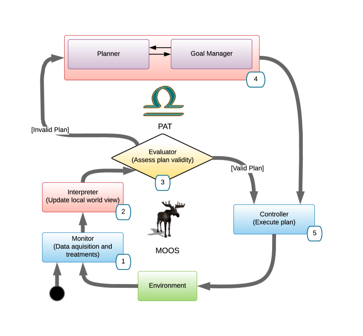
The main operative cycle of GRAVITAS begins with the Monitor (1). This component perceives the environment through the signal processing and fusion of the raw outputs of available sensors. For AUVs, examples of sensors includes accelerometers, gyroscopes, pressure sensors and GPS. It is also in charge of processing these data in order to provide information such as the estimated position and the speed of the agent to the Interpreter (2). This step notably involves techniques such as target tracking which we will not detail here challa*b . Once the Interpreter (2) receives the required information, it updates the agent’s local model of the system and its environment. This formally defined local model is then forwarded to the Evaluator (3) – a component in charge of assessing the validity of the previously established plan with respect to pre-defined specifications. If the Evaluator assesses the plan as valid, the Controller (5) is tasked with executing the plan. Otherwise, if the Evaluator (3) finds the plan invalid e.g., an uncertain event creates inconsistencies in the previously established plan and the mission requirements, a new plan needs to be formulated. The formulation of a new plan is accomplished by the joint operation of the Planner and Goals Manager components (4). After a new plan is formulated, the Controller (5) is tasked with executing this plan. This step involves processing based on control theory lee1967foundations which we do not discuss here.
The components in the lower loop in Figure 2 are orchestrated via the Mission Oriented Operating Suite newman2008moos (MOOS) – a middleware mainly in charge of the communication. The main computational workload of the Evaluator (3), the Planner and the Goal Manager (4) components are powered by PAT. Note that although conceptually the planner and the goal manager are two separated components, in our implementation they are realised in the same PAT model, as discussed in the examples throughout Section 4. Also, to achieve high efficiency in real-life applications, we use a hybrid approach discussed in Section 4.5.
5.2 Verification of Planning and Goal Reasoning Models
The key advantage of the model checking based approach is that we can formally verify certain properties for the planning and goal reasoning model. This verification guarantees that the model only permits “correct” high-level plans. Since the verified model is directly used to generate high-level plans in the planning and goal reasoning phase, we can ensure that the generated high-level plans not only are optimised by for max rewards (resp. min penalties), but also are “correct” with respect to the verified properties.
The verification itself is straightforward since the model is already in CSP#. We only need to formulate the properties in the specification language (cf. Section 2) and use model checking to verify them.
Example
In the AUV survey example, we are interested in checking whether the model would permit an execution sequence in which the AUV hits an obstacle. The below Boolean condition expresses that the position of AUV does not overlap with any position of obstacles.
Using LTL, we can check whether this condition holds for all subsequent states in the execution. This is realised by an assertion of the form
where is a process in CSP#, is the condition we need to check, and is a modality in LTL that means holds for all subsequent states. The above verification is realised in the code below
and PAT can automatically return “yes” as the result. Thus we obtain the following lemma:
Lemma 1
The example planning and goal reasoning model described in Section 4 does not generate plans where the AUV runs into any obstacle.
Using the same technique, we have verified the following lemmas:
Lemma 2
The example model described in Section 4 does not generate plans where the AUV runs out of battery during the mission.
Lemma 3
The example model described in Section 4 does not generate plans where the AUV surfaces at a location within 3 units of distance of a hostile vessel.
5.3 Interacting with Un-trusted Components
Although the Level 2 planning and goal reasoning model in Table 1 suffices in our demonstration of the AUV survey mission, there might be other applications where model checking cannot provide detailed plans in time. For instance, the user may need to adopt heuristic-based planning techniques for UAVs and land vehicles because they run faster.
Inspired by Clarke et al.’s counterexample-guided abstraction refinement Edmund2000 , we propose to integrate heuristic-based planning techniques as an “un-trusted component” as follows: We treat the heuristic method as an high-level plan generator. Whenever the heuristic method generates a plan, we simulate this plan using the corresponding high-level planning and goal reasoning model, i.e., the CSP# model, in PAT. This simulation is much faster than model checking because we only need to check one path of actions instead of checking all paths. If the simulation is successful, then this plan is in the set of plans that can be generated by the CSP# model. If the CSP# model has been verified as described in Section 5.2, then this plan is correct with respect to the verified properties. If the simulation fails, then we add the old plan into a set of disabled plans and constraints the heuristic method such that it does not generate one of the disabled plans. This procedure provides plans that have the same formal guarantee as those generated by PAT, but this procedure may not yield optimal plans. Nonetheless, this procedure provides the means to interact with existing heuristic-based planning techniques generally employed without safe-guards in a reliable way.
6 Implementation of GRAVITAS
In situ experimentation is very expensive and slow. While it is mandatory to the final evaluation of the implementation, in this paper we focus on assessing and demonstrating the feasibility of the proposed goal reasoning and planning approach in a virtual environment. Notable challenges include controlling the complexity of the GTN so that the embedded hardware of the AUV is able to carry the computational load in a reasonable time (i.e., less than a minute) and the transposition of a discrete plan as issued by PAT into its continuous counterpart so that it can be enacted by the AUV.
We have implemented the proposed approach and integrated it within a virtual environment closely simulating the mission described in Section 3. We first introduce the integration of PAT within a community of MOOS applications newman2008moos . We then report the obtained results and discuss the conclusion drawn from them.
The experimental setup is composed of a MOOS application community (referred to as the “community” in the sequel) that corresponds to the AUV internal software environment as well as a set of applications that aim at simulating the external environment. This community includes the following:
- MOOSDB:
-
All communication happens via this central server application.
- uSimMarine:
-
A 3D vehicle simulator that updates vehicle state, position and trajectory, based on the present actuator values and prior vehicle state.
- pMarinePID:
-
A PID controller for heading, speed and depth.
- pMarineViewer:
-
A GUI rendering vehicles and associated information during operation or simulation.
- pSideScanner:
-
A simulator that reports objects identified by the side scanners of the simulated AUV.
- pPATApp:
-
The application that integrate PAT and provide goal reasoning and planning ability to the AUV.
pPATApp implements the GRAVITAS framework as described in Section 5. It subscribes to and monitors channels which broadcast information about the general state of the AUV (e.g., position, speed, heading) as well as information about the objects detected by the side scanners. Then, at each iteration of its internal loop, it interprets this information and models a local world view of the environment. Based on this internal representation and according to the proposed planning approach, it evaluates the actual plan being enacted and, if required, updates it before enacting it by publishing the desired heading, speed and depth of the AUV to the community.
The plan issued by PAT as a part of the re-planning step is a discrete sequence of primitive tasks (e.g. go to 3D position) that require some processing in order to be enacted by the AUV as actuators commands (e.g., set heading, set speed). For instance, the trajectory between several way-points set by the plan has to be compliant with the maximum turn-rate of the AUV. To solve this issue, as a proof of concept we implemented an algorithm based on piecewise Bezier curves composition with continuous curvature constraint for continuous path planning choi2010piecewise . In the future we plan on using a more advanced low-level planning approach such as the FMT* algorithm janson2015fast that will enable us to consider trajectories based on 3D current dynamics as well as uncertainty in the AUV position.
7 Simulation in MOOS pMarineViewer
We demonstrate a case study scenario in a simulation in MOOS. In this scenario, we intend to capture GRAVITAS’s capabilities in dealing with dynamic events during execution. We create a survey mission similar to Figure 1. Note that although the following screenshots are in 2D, the simulation is actually in a 3D environment.
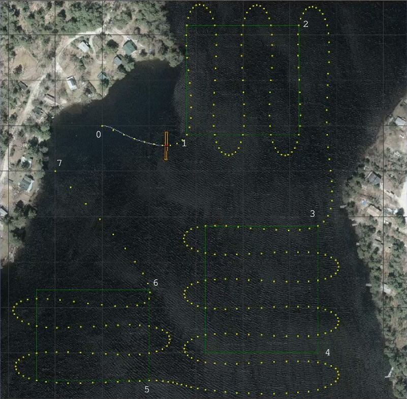
We set 3 survey areas: lower-left (LL), upper-right (UR), and lower-right (LR), with rewards 22807, 51918, 31313 respectively. Initially, the AUV has an energy level of 60000. During execution, we randomly generate a strong water current, with a chance of 20%, that doubles the energy consumption for an uncertain period of time. For simplicity in this example, we trigger goal reasoning and re-planning at the end of each survey area, although these can be done as frequently as required provided that the computation does not take longer than the interval between re-plannings.
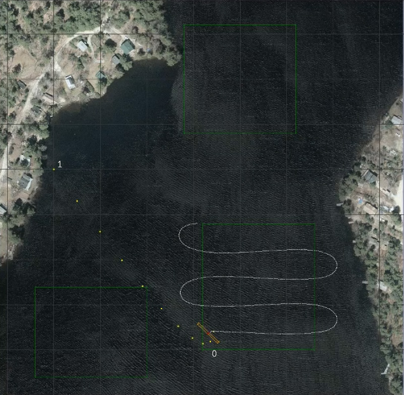
Figure 3(a) shows the initial plan computed by GRAVITAS. The numbers indicate the high-level plan computed by PAT and the dots indicate the low-level plan generated by the actuator. That is, PAT finds the optimal order as well as the entry and exit points for the survey areas, and the actuator computes a smooth path that the AUV can follow. The “wing” of the AUV indicates the coverage of the side scan sonar.
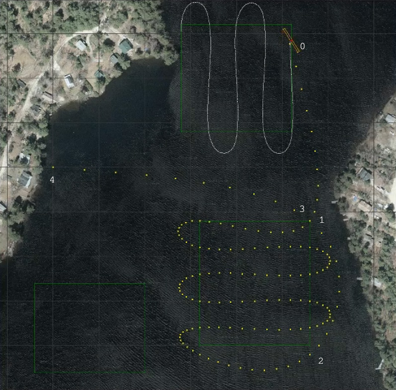
In this run, the random generator creates a strong current during the first survey. As a result, the expected energy consumption for the first survey is 14400, but the actual consumption is 23284. Consequently, the Interpreter in GRAVITAS uses a simple “learning” to update the expected energy consumption for future execution to 162% of the estimation. However, this unexpected change causes re-planning in which PAT decides that there is insufficient energy to complete 3 survey areas, and then finds a new plan to optimise the outcome, as shown in Figure 3(b). In the new plan, PAT chooses to only survey area LR because it yields more reward.
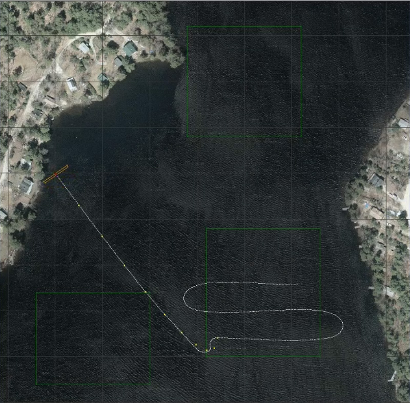
During the transit to the second survey, the water current has returned to normal. At the end of the second survey, the Controller in GRAVITAS discovers that survey area LR has been fully covered before going through the last pass in the “lawn-mowing” pattern. Therefore it triggers re-planning and PAT and the actuator enact a new plan, shown in Figure 3(c), to directly go to the rendezvous point. At the same time, the Interpreter captures that the expected energy consumption for the second survey is 27216, but the actual consumption is 17411, so it lowers the scale of future energy consumption to 104% of the estimation. There is no more strong current on the way to the rendezvous point, and the expected energy consumption is roughly the same as the actual value, and the AUV successfully finishes the mission, as shown in Figure 3(d). In this case study, the (re-)planning takes around 1 second, which is fast enough for the operation of AUV.
8 Related Work
Different approaches exist according to the assumptions about the domain, the goals, the plans and the planning algorithm. Conceptually, the domain evolves according to the performed actions, a controller provides the actions according to the observations on the domain and a plan Ghallab2016 . An example of applying automated reasoning techniques on planning is Kress-Gazit et al.’s framework which automatically translates high-level tasks defined in linear temporal logic formulae to hybrid controllers KressGazit2009 . This framework allows for reactive tasks, which may change depending on the information the robot gathers at runtime. This is similar to the goal reasoning literature where goals may change depending on the environment at runtime.
This work follows the “planning as model checking” paradigm, which dates back to 1990s, e.g., in the work by Giunchiglia and Traverso giunchiglia1999planning . They proposed to solve (classical) planning problems model-theoretically, where planning domains are formalised as semantic models, properties of planning domains are formalised as temporal formulae, and planning is done by verifying whether temporal formulae are true in a semantic model. This idea has been studied and improved in their subsequent work cimatti2000conformant ; cimatti1997planning ; bertoli2001heuristic , which involves using Binary Decision Diagram based heuristic symbolic search. Similar ideas have been used in planners such as MIPS edelkamp2001mips , which can effectively handle the STRIPS subset of the PDDL, and some additional features in ADL.
Closely related to the above work is the verification and validation (V&V) based method of Bensalem et al. bensalem2014verification . They argue that constructing correct and reliable planning systems is error-prone due to the non-deterministic nature of planning problems, thus it is important to develop V&V methods for planners to ensure that the generated plans are correct. To achieve this, the authors proposed to use V&V techniques to perform planning, and use planning to perform V&V. This work is similar in the sense that we are using model checking techniques to perform planning, and since the planning system is built upon the model checker, we can also verify correctness and safety issues of the plans and goals. As a result, we can not only output plans that are efficient in certain criteria, but also those that are verified safe and correct, which is essential in building trusted intelligent agent and is often required in mission-critical operations.
Goal reasoning has been used in a number of projects about controlling autonomous machines in a dynamic environment. Many goal reasoning systems follow a note-assess-guide procedure, and extend it with a cycle of executions to handle the dynamics of the environment and perform goal reasoning and re-planing on-the-fly. Cox et al. Cox2016 propose to use classical planning to formalise goal reasoning. They present an architecture with a cognitive layer and a metacognitive layer to model problem-solving and dynamic event management in self-regulated autonomy. The architecture is realised in the Metacognitive Integrated Dual-Cycle Architecture (MIDCA) version 1.3, which is shown useful in experiment. A detailed account is given by Dannenhauer dannenhauer2017self .
Roberts et al. RobertsAJAWA15 give more detailed definitions of goal reasoning in their framework. They divide the states and goals into two parts: the external part is a modified or incomplete version of the transition system, and the internal part represents the predicates and state required for the refinement strategies. The authors use a data structure called goal memory to represent the relationship between goals, subgoals, parent goals etc., and propose to solve the goal reasoning problem using refinement. They use a goal lifecycle model to capture the evolution of goals and the decision points involved in the process. The goal lifecycle includes the formulation, selection, expansion, execution, dispatch, evaluation, termination, and discard of goals. This model is adapted by Johnson et al. Johnson2016 , who give a system called Goal Reasoning with Information Measures. In the scenario of controlling Unmanned Air Vehicles to survey certain areas, the goals are formulated with parameters such as maximum uncertainty in the search area, acceptable uncertainty under which the goal is considered complete, and deadline by which the search must complete. The goal reasoning method is shown useful for unmanned aerial vehicles operating in dynamic environments.
A more theoretical foundation about planning and goal reasoning is surveyed by Alford et al. ASR16 . The authors unify HGN planning and HTN planning into GTN planning. They also provide plan-preserving translations from GTN problems to HTN semantics. Several computability and tractability results are given. For example, GTN, HTN, and HGN are semi-decidable, and a restricted form called is NEXPTIME. An application of HTN planning realised by symbolic model checking is presented by Kuter et al. Kuter2005AHT . While their work is focused on the theoretical foundation of the problem and they assume full-observability, this paper is more concerned with a more concrete real-life problem: the execution of the AUV in an uncertain environment. Thus this paper is more focused on practical issues that arise when solving the AUV survey problem.
One interesting use case of goal reasoning is goal selection. Rabideau et al. RabideauCM11 give a tractable goal selection method algorithm specialised for selecting goals at runtime for re-planning in a system where computational resources are limited and the complete goal set oversubscribe available resources. Kondrakunta and Cox Kondrakunta2017 also consider the situation where an agent has more goals than can complete in a given time constraint and show how an intelligent agent can estimate the trade-off between performance gains and resource costs. Another important aspect of goal reasoning is to detect inconsistency or incompatibility of goals and plans. Tinnemeier et al. Tinnemeier2008 propose a mechanism to process incompatible goals which have conflicting plans. They argue that the agent should not pursue goals with conflicting plans, and their mechanism can help the agent choose from incompatible goals.
An important application of our project is applying the planning and goal reasoning framework to AUVs. Among many relevant papers, goal reasoning for AUVs Wilson2016 is particularly interesting. The authors use a goal-driven autonomy conceptual model which has three parts: the planner, the goal controller, and the state transition system. The goal reasoning problem is formalised in PDDL, which is the standard language for representing classical planning problems and is widely used by many planners. The authors test their approach in simulations where the AUV surveys a defined area and it has to respond (change the goal) to the actions from a nearby unmanned surface vehicle dynamically. Cashmore et al.’s work Cashmore2018 describes a planning algorithm for AUVs. Like many other related papers, their work assumes certain requirements that are slightly different from our settings. For example, they are focused on temporal planning with time constraints whereas our mission does not have such constraints.
9 Conclusion
This work describes a decision-making framework named GRAVITAS for autonomous systems. The GRAVITAS framework not only provides theoretical foundation for hierarchical planning and goal reasoning, i.e., modelling GTNs using CSP# and using model checking to perform planning and goal reasoning, but also includes practical implementations via the model checker PAT and the MOOS application community. This framework is ultimately realised on a hardware chip that runs on the REMUS-100 AUV. Our simulation has shown that the model checker PAT is sufficient to perform high-level decision making tasks. We have also developed various auxiliary functionalities in GRAVITAS to extend the high-level PAT plan into low-level plans for actuation. An important future work is to improve the level of trustworthiness by extending the verification from high-level plans to low-level plans. We are also planning to conduct more realistic simulations, and will attempt to show in situ ability of our approach in real-world demonstrations.
References
- (1) Alford, R., Shivashankar, V., Roberts, M., Frank, J., Aha, D.W.: Hierarchical planning: Relating task and goal decomposition with task sharing. In: IJCAI, pp. 3022–3029 (2016)
- (2) Anderson, M.L., Oates, T., Chong, W., Perlis, D.: The metacognitive loop I: enhancing reinforcement learning with metacognitive monitoring and control for improved perturbation tolerance. J. Exp. Theor. Artif. Intell. 18(3), 387–411 (2006)
- (3) Bai, G., Lei, J., Meng, G., Venkatraman, S.S., Saxena, P., Sun, J., Liu, Y., Dong, J.S.: Authscan: Automatic extraction of web authentication protocols from implementations. In: NDSS (2013)
- (4) Bensalem, S., Havelund, K., Orlandini, A.: Verification and validation meet planning and scheduling (2014)
- (5) Bertoli, P., Cimatti, A., Roveri, M.: Heuristic search+ symbolic model checking= efficient conformant planning. In: IJCAI, pp. 467–472. Citeseer (2001)
- (6) Cashmore, M., Fox, M., Long, D., Magazzeni, D., Ridder, B.: Opportunistic planning in autonomous underwater missions. IEEE Transactions on Automation Science and Engineering 15(2), 519–530 (2018). DOI 10.1109/TASE.2016.2636662
- (7) Challa, S., Morelande, M.R., Muicki, D., Evans, R.J.: Fundamentals of Object Tracking. Cambridge University Press (2011)
- (8) Choi, J.W., Curry, R., Elkaim, G.: Piecewise bezier curves path planning with continuous curvature constraint for autonomous driving. In: Machine learning and systems engineering, pp. 31–45. Springer (2010)
- (9) Cimatti, A., Giunchiglia, E., Giunchiglia, F., Traverso, P.: Planning via model checking: A decision procedure for ar. In: European Conference on Planning, pp. 130–142 (1997)
- (10) Cimatti, A., Roveri, M.: Conformant planning via symbolic model checking. J. Artif. Intell. Res.(JAIR) 13, 305–338 (2000)
- (11) Clarke, E., Grumberg, O., Jha, S., Lu, Y., Veith, H.: Counterexample-guided abstraction refinement. In: E.A. Emerson, A.P. Sistla (eds.) Computer Aided Verification, pp. 154–169. Springer Berlin Heidelberg, Berlin, Heidelberg (2000)
- (12) Clarke, E.M., Emerson, E.A., Sistla, A.P.: Automatic verification of finite-state concurrent systems using temporal logic specifications. ACM Transactions on Programming Languages and Systems (TOPLAS) 8(2), 244–263 (1986)
- (13) Clarke Jr., E.M., Grumberg, O., Peled, D.A.: Model Checking. MIT Press, Cambridge, MA, USA (1999)
- (14) Clearwater, S.H.: Market-based control: A paradigm for distributed resource allocation. World Scientific (1996)
- (15) Cox, M.T., Alavi, Z., Dannenhauer, D., Eyorokon, V., Munoz-Avila, H., Perlis, D.: MIDCA: A metacognitive, integrated dual-cycle architecture for self-regulated autonomy. In: AAAI, pp. 3712–3718 (2016)
- (16) Dannenhauer, D.: Self monitoring goal driven autonomy agents. Ph.D. thesis, Lehigh University (2017)
- (17) Dillig, I.: Lecture notes on automated logical reasoning. https://www.slideshare.net/pvcpvc9/lecture17-31382688 (Accessed 2018)
- (18) Edelkamp, S., Helmert, M.: Mips: The model-checking integrated planning system. AI magazine 22(3), 67 (2001)
- (19) Erol, K., Hendler, J.A., Nau, D.S.: UMCP: A sound and complete procedure for hierarchical task-network planning. In: AIPS, vol. 94, pp. 249–254 (1994)
- (20) Ghallab, M., Nau, D., Traverso, P.: Automated Planning and Acting, 1st edn. Cambridge University Press, New York, NY, USA (2016)
- (21) Giunchiglia, F., Traverso, P.: Planning as model checking. In: European Conference on Planning, pp. 1–20. Springer (1999)
- (22) Hoare, C.A.R.: Communicating sequential processes. Communications of the ACM 21(8), 666–677 (1978)
- (23) Huth, M., Ryan, M.: Logic in Computer Science: Modelling and Reasoning About Systems. Cambridge University Press, New York, NY, USA (2004)
- (24) Institute, D.S.: Wizard of aus 2018 an autonomous warrior 2018 trial. http://www.defencescienceinstitute.com/2017/11/06/wizard-aus-2018-autonomous-warrior-2018-trial/ (2018)
- (25) Institution, W.H.O.: Remus 100. http://www.whoi.edu/main/remus100 (2018)
- (26) Janson, L., Schmerling, E., Clark, A., Pavone, M.: Fast marching tree: A fast marching sampling-based method for optimal motion planning in many dimensions. The International journal of robotics research 34(7), 883–921 (2015)
- (27) Johnson, B., Roberts, M., Apker, T., Aha, D.W.: Goal reasoning with informative expectations. In: ICAPS Workshop. London, UK (2016)
- (28) Kondrakunta, S., Cox, M.T.: Autonomous goal selection operations for agent-based architectures. In: IJCAI GRW. Melbourne, Australia (2017)
- (29) Kress-Gazit, H., Fainekos, G.E., Pappas, G.J.: Temporal-logic-based reactive mission and motion planning. IEEE Transactions on Robotics 25(6), 1370–1381 (2009)
- (30) Kuter, U., Nau, D.S., Pistore, M., Traverso, P.: A hierarchical task-network planner based on symbolic model checking. In: ICAPS (2005)
- (31) Lee, E.B., Markus, L.: Foundations of optimal control theory. Tech. rep., Minnesota University Minneapolis Center for Control Sciences (1967)
- (32) Newman, P.M.: MOOS-mission orientated operating suite (2008)
- (33) news.com.au: New ocean infinity search for mh370 encountering big problems. http://www.news.com.au/travel/travel-updates/incidents/new-ocean-infinity-search-for-mh370-encountering-big-problems/news-story/89efc71d393585bb3efc1fcd10b765aa (2018)
- (34) Paisner, M., Cox, M.T., Perlis, D.: Symbolic anomaly detection and assessment using growing neural gas. In: Proc. 25th IEEE International Conference on Tools with Artificial Intelligence, pp. 175–181. IEEE Computer Society (2013)
- (35) Pnueli, A.: The temporal logic of programs. In: Proceedings of the 18th Annual Symposium on Foundations of Computer Science, SFCS ’77, pp. 46–57. IEEE Computer Society, Washington, DC, USA (1977)
- (36) Rabideau, G., Chien, S.A., McLaren, D.: Tractable goal selection for embedded systems with oversubscribed resources. JACIC 8(5), 151–169 (2011)
- (37) Roberts, M., Apker, T., Johnston, B., Auslander, B., Wellman, B., Aha, D.W.: Coordinating robot teams for disaster relief. In: Proceedings of the Twenty-Eighth International Florida Artificial Intelligence Research Society Conference, FLAIRS 2015, Hollywood, Florida. May 18-20, 2015., pp. 366–371 (2015)
- (38) Shivashankar, V., Kuter, U., Nau, D., Alford, R.: A hierarchical goal-based formalism and algorithm for single-agent planning. In: Proceedings of the 11th International Conference on Autonomous Agents and Multiagent Systems-Volume 2, pp. 981–988. International Foundation for Autonomous Agents and Multiagent Systems (2012)
- (39) Shivishankar, V.: Hierarchical goal network planning: Formalisms and algorithms for planning and acting. Ph.D. thesis, PhD thesis, Department of Computer Science, University of Maryland College Park (2015)
- (40) Sun, J., Liu, Y., Dong, J.S.: Model checking csp revisited: Introducing a process analysis toolkit. In: T. Margaria, B. Steffen (eds.) Leveraging Applications of Formal Methods, Verification and Validation, pp. 307–322. Springer Berlin Heidelberg, Berlin, Heidelberg (2008)
- (41) Sun, J., Liu, Y., Dong, J.S., Pang, J.: PAT: Towards flexible verification under fairness. pp. 709–714. Springer (2009)
- (42) Tinnemeier, N.A.M., Dastani, M., Meyer, J.J.C.: Goal Selection Strategies for Rational Agents, pp. 54–70. Springer Berlin Heidelberg, Berlin, Heidelberg (2008)
- (43) Valmari, A.: The state explosion problem. In: Advanced Course on Petri Nets, pp. 429–528. Springer (1996)
- (44) Wilson, M.A., McMahon, J., Wolek, A., Aha, D.W., Houston, B.: Toward goal reasoning for autonomous underwater vehicles: Responding to unexpected agents. In: 25th International Joint Conference on Artificial Intelligence (IJCAI) Workshop on Goal Reasoning. New York, NY (2016)