Double moiré with a twist: super-moiré in encapsulated graphene
Abstract
A periodic spatial modulation, as created by a moiré pattern, has been extensively studied with the view to engineer and tune the properties of graphene. Graphene encapsulated by hexagonal boron nitride (hBN) when slightly misaligned with the top and bottom hBN layers experiences two interfering moiré patterns, resulting in a so-called super-moiré (SM). This leads to a lattice and electronic spectrum reconstruction. A geometrical construction of the non-relaxed SM patterns allows us to indicate qualitatively the induced changes in the electronic properties and to locate the SM features in the density of states and in the conductivity. To emphasize the effect of lattice relaxation, we report band gaps at all Dirac-like points in the hole doped part of the reconstructed spectrum, which are expected to be enhanced when including interaction effects. Our result is able to distinguish effects due to lattice relaxation and due to the interfering SM and provides a clear picture on the origin of recently experimentally observed effects in such trilayer heterostuctures.
1 Introduction
Encapsulation of graphene by hBN is a widely used technique for obtaining devices with exceptional electronic properties [1, 2]. This is due to the fact that hBN serves as a protective layer for graphene, isolating it from the contaminants from the environment, and to flatten the graphene layer. Although graphene and hBN have similar crystal structure (difference between lattice constants is ), hBN is an inert band insulator that does not alter the electronic properties of graphene when the two layers are misoriented. In contrast, when different lattices are closely aligned, spectrum [3] and surface [4] reconstruction becomes significant as a consequence of the moiré periodicity between the two or more crystals. Moiré reconstruction further induces effects that are of great importance in the light of gap engineering and insulating phases [5, 6], tuning between metallic and superconductive phases [7] and even exploring interaction effects [8] in hBN/gr multilayers. In addition, recent experimental advancement showed that it is possible to align two monolayer sheets to a high rotation precision of [9, 10]. Even dynamical tuning of the rotation angle with precision below has been demonstrated [11]. Further, high rotation controllability led to encapsulated graphene devices almost aligned to both hBN layers, gaining attention when additional spectrum reconstruction was reported [12, 13, 14].
If a moiré pattern, formed by e.g. two monolayers, is brought in contact with another monolayer, the interference will lead to a super-moiré (SM) structure, leading to additional Dirac-like points. In this report we present a detailed study on the origin of the SM features, the resulting effects on the electronic properties and on the lattice reconstruction. Even in the rigid form, small misorientation in the trilayer creates reconstructed bands that are different from those found in bilayer graphene/hBN systems. We model the effect as a function of the relative twist between the layers and compare the results against a simple, geometrical description of the moiré systems. Further, we discuss the renormalization of the Fermi velocity and the appearance of bands with almost vanishing dispersion. Lastly, we report experimentally detectable band gaps at all Dirac-like points induced by the moiré patterns as a result of lattice relaxation. Moreover, the used methodology can be applied to different almost aligned multilayer-heterostructures with small difference in lattice constants of individual layers where similar effects can be expected.
The paper is organized as follows. In section 2 geometrical properties of hBN/gr/hBN are described and different SM spatial periodicities are derived. Section 3 introduces the non-interacting tight-binding model for rotated gr/hBN heterostructures. Further, in section 4 the effect of the close alignment on the electronic properties is examined, which is followed by discussions on the relaxation effects in section 5. Conclusions of the paper are summarized in section 6.
2 Geometrical considerations in rigid trilayers
Before further exploring the effects of the alignment between graphene and multiple hBN layers, a qualitative description of the moiré pattern is worth reviewing. In its rigid form, graphene and hBN can be defined as bipartite honeycomb lattices, as illustrated in Fig. 1, with unit cell vectors of graphene , , and bottom () and top () hBN , where nm is the length of graphene unit cell, represents a rotation matrix in counter-clock wise direction by an angle , and are the relative ratios between graphene and bottom/top hBN lattice constants, with the unrelaxed value of . Reciprocal vectors are defined as , , satisfying .
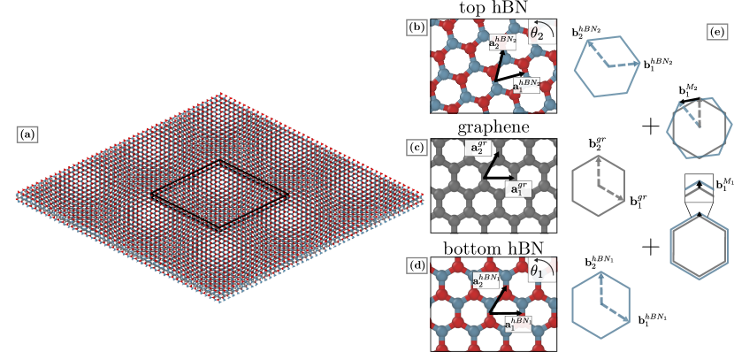
From there, the top and the bottom moiré reciprocal vectors can be defined as a difference between the reciprocal vectors of graphene and hBN, .
The massless Dirac-Weyl equation describes the behaviour of a single graphene layer, while hBN layers can be modeled as an effective potential and a gauge field in the continuum approximation [15]. Still, in the continuum description strain and relaxation effects are fitted parametrically, which results in loosing the generality of the model. This is why in the following a real-space representation of a tight-binding Hamiltonian will be used. In a similar manner as in the continuum description, hBN substrate can be effectively modeled as a modification of both hopping terms and the onsite energy. Following the work in [16], but considering only an additional potential that respects the periodicity of the underlying moiré patterns, the change of the onsite energy is given by
| (1) |
where the parameters and contain the lattice information of the two crystals and the rotation angle between them, and are indexes of the unit cell, , . The two terms in Eq. (1), and denote sublattice symmetric and antisymmetric potential, respectively (due to hBN layer ). Rotated moiré reciprocal lattice vectors are .
In the case of almost aligned graphene with multiple hBN layers, the effective onsite terms will become superposition of the changes due to each of the hBN layers, taking into account the exponential decrease of the interlayer interaction. Without loss of generality, it is further assumed (except when considering the effect of the misalignment) that graphene is perfectly aligned with the bottom hBN layer, while the top hBN is twisted. Taking this into account, in Fig. 2 the superimposed onsite potential in graphene layer, and the Fourier transformation of this potential, originating from the encapsulation, are shown.
From both the real and the reciprocal space it is clear that in addition to the moiré pattern due to aligned bottom hBN (marked in Fig. 2 with black unit cell in real space, and black mini-Brillouin zone in reciprocal space with nm), and the rotated moiré between graphene and top hBN (red colour), there exist additional periodicities of longer range. The Fourier transformation (FT) in reciprocal space further reveals which components are important. From this qualitative analysis, a comprehensive description of possible moiré patterns are obtained. Straightforward geometrical consideration shows that beside the aligned and the rotated graphene-moiré spots in the FT, different combinations of the two result in additional SM patterns, similar to the case of two-layered systems with hexagonal symmetry [17]. The corresponding FT harmonics can be derived as translation (difference) vectors that match the two of the original moiré patterns. Hence, the SM reciprocal vectors can be obtained as a difference between the aligned and rotated reciprocal vectors, or their multiples.
The real space description of the SM starts with previously introduced graphene and hBN lattices and the corresponding moiré patterns. From there, an arbitrary super-moiré vector is
| (2) |
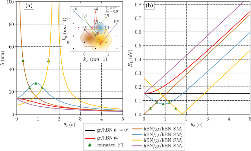
where denotes the element-wise product with . This frequency analysis leads to analytical expressions for possible SM patterns obtained for an arbitrary rotation between the two moiré patterns. The shortest reciprocal (or the longest real space) SM vectors are the ones affecting the low energy spectrum. Different SM harmonics at low rotation angles which emerge as the difference between the moiré harmonics of different order agree well with the experimentally observed features from [14]. These are shown in the inset of Fig. 3, where the coloured hexagons represent their mini-Brillouin zones. Under the assumptions of , and , four different low-energy, low-angle harmonics, which will be later used for comparison against the numerical results, and the corresponding real space periodicities (using relation ) are
| (3) | ||||||||
as being shown in Fig. 3(a). Further, energy of the reconstruction is related to the period as and is shown in Fig. 3(b).
Previous consideration also applies for any combination of 2D materials with honeycomb lattice. Notice that it is the close matching of the lattice constants of the two materials that results in the reconstruction of both the energy dispersion through the formation of moiré induced mini-bands and secondary Dirac points (SDPs) and the reconstruction of the surface due to the van der Waals interaction as further discussed in section 5.
The qualitative analysis of multiple superimposed moiré patterns does not include a quantitative description of the coupling between the layers. Experimental reports have shown that the van der Waals coupling leads to straining of the lattice, resulting in a commensurate state of the hBN/gr bilayers for almost aligned structures with angle smaller than [4]. For larger rotation angles, the hBN potential only weakly affects the graphene layer due to the fast moiré oscillations [4]. It is only in the regime of highly coupled layers that the fine effect of mini-band formation will occur. This is why in the following section, hBN/gr/hBN trilayers are simulated following the real space methodology, where the hBN layers are considered fully and not as an effective potential, which captures the subtle SM and, after relaxing the sample, the strain effects.
3 Model and methodology
We start from the graphene-hBN non-interacting TB Hamiltonian [15]
| (4) |
with the hopping term between sites and defined based on the Slater-Koster like terms [18]
| (5) |
| (6) |
with and are intralayer and interlayer hopping integrals, respectively. Carbon-carbon distance in graphene is nm, nm is the interlayer distance between graphene and hBN layers, is the vector between two sites, is the distance between them, and is chosen in order to fit the next-nearest intralayer hopping to . Onsite terms of boron and nitrogen species are set to and . We have taken into account the next-next-nearest neighbour coupling in graphene, and the coupling within the radius of in between graphene and hBN layers.
For obtaining electronic properties from the Hamiltonian defined in Eq. (4) the kernel polynomial method (KPM) [19] implemented in Pybinding [20] is used. Band structure is calculated as the density of states (DOS) of a -dependent Hamiltonian, where takes its values along significant points in the super-moiré mini-Brillouin zone. The total DOS in the periodic system can be defined as , where takes values from the full super-moiré mini-Brillouin zone, and is the total number of points.
In general, the simulated structure for arbitrary rotation angles and is incommensurate, which means that the unit-cell is not properly defined. Commensurate lattice appears when an additional condition given by the Diophantine equation is fulfilled
| (7) |
together with as given in Eq. (3). These conditions are only met for a discrete set of rotation angles, which are sparsely distributed at low twists. To be able to obtain bulk properties of systems with an arbitrary rotation, angle dependent local density of states (LDOS), spatial distribution of the LDOS and the Kubo DC conductivity in the linear response regime, as presented in [21], are calculated using circular hBN/gr/hBN flakes with radius nm, where the effect of the boundaries is minimized by using absorbing boundary conditions [22, 23, 24]. High resolution conductivity results are obtained using the single-shot algorithm [25]. For calculating the DC conductivity, Anderson disorder (zero average onsite energy) with width of is considered. Typically 15000 KPM moments are computed, and Lorentz kernel is used for reconstructing desired quantities.
We also performed molecular dynamics simulations (MD) for the double aligned structure for relaxing the structure. This was done through total energy minimization of the unit cell, with certain constraints. We used the Brenner potentials for the graphene layer, Tersoff potentials for the B-N interaction in the top hBN and the Morse potential developed in [26] for the inter-layer interactions. Simulations were performed within the "Large-scale atomic.molecular massively parallel simulator" (LAMMPS) software [27, 28]. In order to mimic a thicker hBN substrate (in most of the experimental setups hBN substrate is usually a thick slab [29]) we fixed the bottom hBN configuration, while only allowing the relaxation of the other two layers. The total energy was minimized until the error in forces calculated between two iteration steps was below eV/Å.
4 Evidence of the super-moiré in the electronic properties
To further investigate the behaviour of the hBN/gr/hBN system we consider all three layers, as well as coupling between them. All three layers are kept rigid, and the lattice relaxation is discussed later in detail. The change of the LDOS with tuning the rotation angle is shown in Fig. 4. In panels (a) the LDOS of a lattice site of graphene that sits on top of boron and in (b) for a graphene lattice site on top of a nitrogen atom from the bottom layer are shown for low rotation angles. In agreement with previous theoretical descriptions of bilayer gr/hBN samples [15, 30], strong asymmetry between electron and hole states exists, with much stronger features on the hole doped side. This asymmetry can be traced back to the correlation between spatial variations of the onsite energy and the variations in the effective hopping with neighboring atoms in the graphene layer [31].
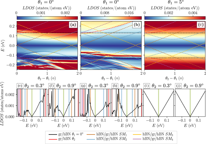
Focusing on panels (a) and (b) of Fig. 4, one notices that different SM reconstruction points can be observed. The band gap that occurs in LDOS between energies meV (marked with black dashed line) remains constant in energy with rotation angle. Converting the energy to the corresponding period gives nm, which can be addressed to the SDP from the aligned graphene/hBN moiré pattern. The dip in the LDOS observed at energy lower than this one corresponds to the secondary Dirac point due to graphene and rotated graphene hBN, and is marked with red dashed curve. Additionally, in the low energy regime, LDOS exhibits a series of peaks marked with brown, blue and yellow dashed curves, again stronger on the hole doped side. Having in mind that these dips appear at lower energies than the SDPs due to aligned and rotated hBNs, they can be attributed to the SM periods. In fact, these are none other than angle-energy features of three harmonics as defined by Eq. (3) and shown in Fig. 3(b), which are now reproduced in all panels. In contrast with the plot in Fig. 2(b), suppressed Fermi velocity of m/s was used in order to obtain good agreement between the SM features in the LDOS and the derived harmonics, suggesting that the SM effect alters the electron velocity.
The pronounced sublattice asymmetry when comparing the LDOS of the two graphene sublattices in panels (a) and (b) of Fig. 4 is resulting from the local stacking arrangement between graphene and the encapsulating hBN layers. As mentioned previously, important aspect not considered in section 2 is the strength of the interlayer coupling. Weaker features on the electron doped side and the disappearance of the SM features cannot be explained with former description. It is the effect of the interlayer coupling that is reflected in the appearance of SM dips. Once the effective interlayer coupling is weakened through the effect of the misalignment, similar as in the case of the commensurate-incommensurate transition [4], the effect of the SM is lost. To further explore the importance of close-alignment, Fig. 4(c) shows the LDOS of misaligned graphene layer of with the same relative angle between the two hBN layers as in Figs. 4(a) and (b), and we see no signatures of SM. This explains why the SM effect is only recently reported [12, 13, 14] when one was able to achieve accurate control over the rotation angle between the layers, although hBN encapsulation has been a technique of choice for graphene transport devices for a much longer period [1].
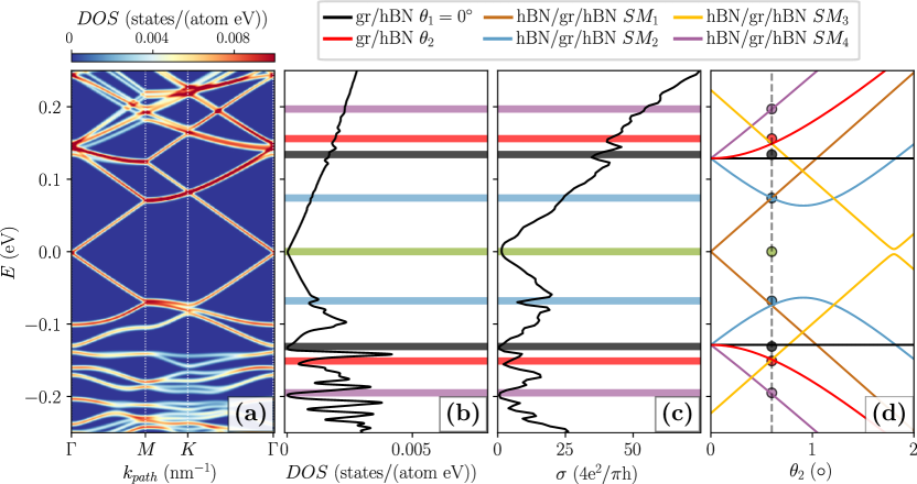
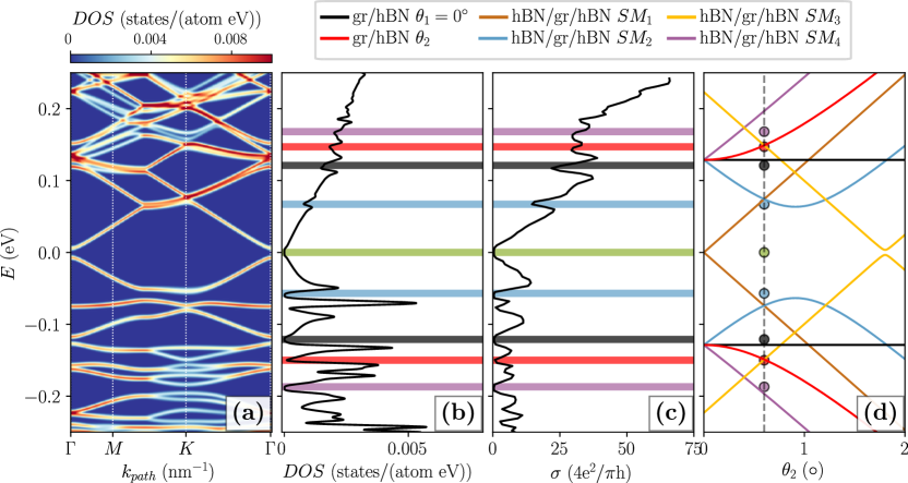
In Fig. 5 band structure, density of states (DOS), and the conductivity of the hBN/gr/hBN system with are shown and compared against the expected energy of different moirés from section 2. Significant energies are marked with coloured stripes, each one corresponding either to the moiré or SM effect labeled in Fig. 2(c) and Fig. 5(d), or to the primary Dirac point of graphene. Band structure and the corresponding DOS are important to unravel the different SM effects on the two types of carriers. At positive Fermi energies (electron doped side), around meV, a Dirac-like point appearing at the point of the superlattice mini-Brillouin zone is observed within the probing resolution. In contrast, the hole doped SM effect results in the appearance of band anti-crossing around meV, implying a different effect of the two features on the electronic properties. Further, due to the band folding, the moiré SDPs are appearing at the and the point of the SM mini-Brillouin zone at energies meV and meV, respectively. In between the two SDPs on the hole doped side, a band with reduced Fermi velocity appears, reflecting in a peak in the DOS. Due to its small dispersion low conductivity can be observed. Compared against the SM effect in the DOS, transport properties reveal less pronounced electron-hole asymmetry, with drops in the conductivity around the SM energy at both sides. In Fig. 5(d), different features are compared against the expected energy at which the moiré harmonics affect the spectrum. Vertical line intersect different harmonics at angle , while the circular markers are obtained from Fig. 5(b) and (c), once again confirming their origin.
In addition, further comparison between local properties - LDOS, and global - DOS and conductivity is given in the Supplementary information, section S3, showing that the SM effect in transport vanishes already at rather small angles of , different from the effect on the LDOS shown in Fig. 4, where it was observed even for rotations larger than .
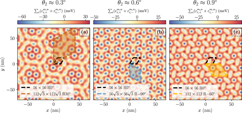
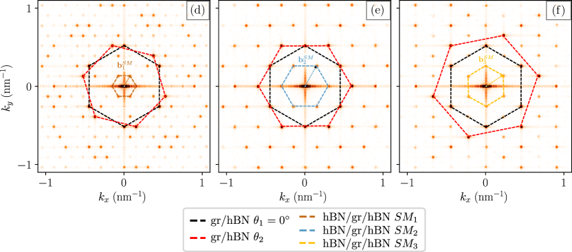
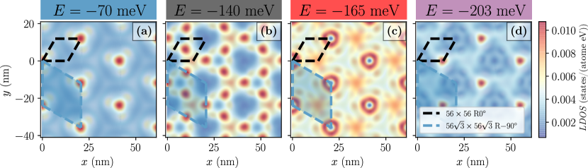
Although STM measurements in this type of samples would remain a practical challenge due to the encapsulation with the top hBN layer, it is interesting to discuss the SM effects on the spatial distribution of the LDOS (SLDOS). As expected, SLDOS is modulated by the hexagonally symmetric potential which originates from moiré patterns with different spatial lengths. In Fig. 6(a) clear modulation respecting the symmetry of the super-moiré can be observed. The energy is just above the SM induced Dirac-like point, where the modulation is the strongest. Notice that the highest LDOS appears in the corners of the SM unit-cell, where graphene atoms are maximally covered with boron and nitrogen atoms from both the top and the bottom hBN. Differently, in Figs. 6(b-d) close to the and moiré SDPs, different symmetry of the SLDOS patterns reveals the dominant effect of the two underlying moirés. In this case, the LDOS distribution at the corners of the SM is minimized.
5 Enhancement of super-moiré by lattice relaxation
When graphene and hBN are put on top of each other and aligned, two effects occur. Firstly there is band energy reconstruction through the appearance of mini-bands and of secondary Dirac points. The second effect is related to the van der Waals energy which is minimized through the formation of stacking areas with minimal energy [4]. This induces strain which further changes the tunnelling probability (or the hopping energy) throughout the sample. In the case of incommensurate alignment of layers, when no or little relaxation occurs, the effects of the opposite boron and nitrogen species on the graphene layer are averaged out on the area of the moiré unit cell, and no gaps appear [4].
Relaxation changes the interatomic registry, which results in the appearance of significant gaps at the primary and secondary Dirac points [32, 33], which was confirmed experimentally [4, 5, 6, 13, 34, 35].
If the goal is to preserve the gapless linear spectrum, an addition of misaligned top layer to the hBN substrate, would again average out the mass-like boron/nitrogen terms and preserve the gapless graphene spectrum. More interesting effects come into play when the second hBN layer is close to align [13].
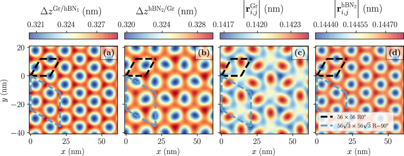
The sample relaxation was done using MD simulations. Bottom hBN layer is kept rigid to mimic the effect of a thick substrate, while graphene and top hBN are freely relaxed. The resulting effect on the interlayer distance () and the bond lengths () is shown in Fig. 7. Interlayer distance between graphene and bottom hBN in Fig. 7(a) shows a clear evidence of the symmetry which follows the moiré pattern between these two layers, as marked with the black unit cell. Notice also that the bond lengths in top hBN reveal the symmetry of the moiré between graphene and this layer shown in (d). In contrast, the distance between top hBN and graphene in panel (b) and the distribution of the bond lengths in graphene in panel (c) follow the symmetry of the SM, marked with the blue unit cell. This shows that the SM is imprinted in the in-plane distribution of the strain in graphene, and the interlayer distance between graphene and the relaxed hBN layer, modifying in such a way all the hopping terms in Eq. (6) and further enhancing the super-moiré effect.
In the electronic spectrum, both the rigid, Fig. 5(a), and the relaxed sample, Fig. 8(a), show similar behaviour around the two SDPs at the hole side. The main difference is that in the relaxed sample gaps appear at the primary (see figure S5 in [14]), and in both of the secondary Dirac points on the hole doped side [33], consistent with broken inversion symmetry where the gap does not average out over the area of the SM pattern. It is important to note that relaxation effects are believed to be only partially responsible for the appearance of the experimentally observed gaps, while they are expected to increase when many-body interactions are included [5, 32, 36].
More importantly, the band structure in Fig. 8(a) reveals a gap at the hole doped SM Dirac-like point as well. The appearance of the SM reconstruction is highly tunable within the low energy spectrum through the change of the twist angle. In the small misalignment regime, the minimization of the van der Waals energy induces surface reconstruction that further results in SM gaps. Hence, the hBN/gr/hBN trilayers might provide a feasible route for gap engineering at arbitrary energies, which was not possible previously in moiré like structures. Simply, the lowest energy SDP ( meV) is limited by the largest bilayer hBN/gr period which is nm.
The slight misalignment brings the two SDPs to a close proximity, which then results in the appearance of a narrow band in between the two energy features, and [13]. Due to relaxation of the sample, this band becomes even narrower. In addition, the SM gap edge shows similar dispersionless property, which was absent in the rigid sample. This means that by relaxing the sample, two almost flat bands appear, which suggests even richer physics in this regime.
Relaxation partially recovers the electron-hole symmetry in the spectrum. Although gaps appear only in the hole doped side, the moiré and SM become more visible on the electron side, as shown in the DOS, Fig. 8(b), and the conductivity, Fig. 8(c).
6 Conclusion
To conclude, we have examined and showed the effects of slightly misaligned hBN encapsulation layers on the electronic properties of monolayer graphene. A simple model in terms of Bragg scattering vectors is able to explain the origin of the super-moiré spectrum. Using a real space tight-binding method we have quantitatively described the angle dependent SM effects that result in additional spectrum reconstruction, velocity suppression and spatial electron redistribution.
In addition to rigid alignment between the layers, we have studied the effects of lattice relaxation. Bottom hBN layer was kept rigid, which simulates the effect of a thick substrate, while the top hBN and graphene were freely relaxed. By relaxing the trilayer sample, the SM features are enhanced, and multiple asymmetrical low-energy gaps and flat bands whose energy can be controlled by misalignment appear. The opening of band-gaps, and the expected enhancement due to many-body interactions appearing alongside flat bands are of high interest to the community working on twisted 2D (hetero)structures. The fact that flat bands are apparent in the case of graphene almost aligned to two encapsulated hBN layers, means only that further theoretical studies starting from the picture of interacting electrons are needed to understand all the different aspects of close aligned hBN/gr/hBN layers.
Acknowledgements
This work was funded by FLAGERA project TRANS2DTMD and the Flemish Science Foundation (FWO-Vl) through a postdoc fellowship for S.P.M. The authors acknowledge useful discussions with W. Zihao and K. Novoselov.
References
References
- [1] Mayorov A S, Gorbachev R V, Morozov S V, Britnell L, Jalil R, Ponomarenko L A, Blake P, Novoselov K S, Watanabe K, Taniguchi T and Geim A K 2011 Nano Letters 11 2396–2399 URL https://doi.org/10.1021/nl200758b
- [2] Kretinin A V, Cao Y, Tu J S, Yu G L, Jalil R, Novoselov K S, Haigh S J, Gholinia A, Mishchenko A, Lozada M, Georgiou T, Woods C R, Withers F, Blake P, Eda G, Wirsig A, Hucho C, Watanabe K, Taniguchi T, Geim A K and Gorbachev R V 2014 Nano Letters 14 3270–3276 URL https://doi.org/10.1021/nl5006542
- [3] Yankowitz M, Xue J, Cormode D, Sanchez-Yamagishi J D, Watanabe K, Taniguchi T, Jarillo-Herrero P, Jacquod P and LeRoy B J 2012 Nature Physics 8 382–386 URL https://doi.org/10.1038/nphys2272
- [4] Woods C R, Britnell L, Eckmann A, Ma R S, Lu J C, Guo H M, Lin X, Yu G L, Cao Y, Gorbachev R V, Kretinin A V, Park J, Ponomarenko L A, Katsnelson M I, Gornostyrev Y N, Watanabe K, Taniguchi T, Casiraghi C, Gao H J, Geim A K and Novoselov K S 2014 Nature Physics 10 451–456 URL https://doi.org/10.1038/nphys2954
- [5] Hunt B, Sanchez-Yamagishi J D, Young A F, Yankowitz M, LeRoy B J, Watanabe K, Taniguchi T, Moon P, Koshino M, Jarillo-Herrero P and Ashoori R C 2013 Science 340 1427–1430 URL https://doi.org/10.1126/science.1237240
- [6] Chen Z G, Shi Z, Yang W, Lu X, Lai Y, Yan H, Wang F, Zhang G and Li Z 2014 Nature Communications 5 4461 URL https://doi.org/10.1038/ncomms5461
- [7] Chen G, Sharpe A L, Gallagher P, Rosen I T, Fox E J, Jiang L, Lyu B, Li H, Watanabe K, Taniguchi T, Jung J, Shi Z, Goldhaber-Gordon D, Zhang Y and Wang F 2019 Nature 572 215–219 URL https://doi.org/10.1038/s41586-019-1393-y
- [8] Chen G, Jiang L, Wu S, Lyu B, Li H, Chittari B L, Watanabe K, Taniguchi T, Shi Z, Jung J, Zhang Y and Wang F 2019 Nature Physics 15 237–241 URL https://doi.org/10.1038/s41567-018-0387-2
- [9] Kim K, DaSilva A, Huang S, Fallahazad B, Larentis S, Taniguchi T, Watanabe K, LeRoy B J, MacDonald A H and Tutuc E 2017 Proceedings of the National Academy of Sciences 114 3364–3369 URL https://doi.org/10.1073/pnas.1620140114
- [10] Cao Y, Fatemi V, Fang S, Watanabe K, Taniguchi T, Kaxiras E and Jarillo-Herrero P 2018 Nature 556 43–50 URL https://doi.org/10.1038/nature26160
- [11] Ribeiro-Palau R, Zhang C, Watanabe K, Taniguchi T, Hone J and Dean C R 2018 Science 361 690–693 URL https://doi.org/10.1126/science.aat6981
- [12] Wang L, Zihlmann S, Liu M H, Makk P, Watanabe K, Taniguchi T, Baumgartner A and Schönenberger C 2019 Nano Letters 19 2371–2376 URL https://doi.org/10.1021/acs.nanolett.8b05061
- [13] Finney N R, Yankowitz M, Muraleetharan L, Watanabe K, Taniguchi T, Dean C R and Hone J 2019 arXiv:1903.11191 [cond-mat] (Preprint https://arxiv.org/abs/1903.11191)
- [14] Wang Z, Wang Y, Yin J, Tovari E, Yang Y, Lin L, Holwill M, Birkbeck J, Perello D, Xu S, Zultak J, Gorbachev R, Kretinin A, Taniguchi T, Watanabe K, Morozov S, Anđelković M, Milovanović S, Covaci L, Peeters F M, Mishchenko A, Geim A, Novoselov K, Fal’ko V, Knothe A and Woods C 2019 To appear in Science Advances ISSN 2375-2548
- [15] Moon P and Koshino M 2014 Physical Review B 90 155406 URL https://doi.org/10.1103/physrevb.90.155406
- [16] Diez M, Dahlhaus J, Wimmer M and Beenakker C 2014 Physical Review Letters 112 196602 URL https://doi.org/10.1103/physrevlett.112.196602
- [17] Zeller P and Günther S 2014 New Journal of Physics 16 083028 URL https://doi.org/10.1088/1367-2630/16/8/083028
- [18] Slater J C and Koster G F 1954 Physical Review 94 1498–1524 URL https://doi.org/10.1103/physrev.94.1498
- [19] Weiße A, Wellein G, Alvermann A and Fehske H 2006 Reviews of Modern Physics 78 275–306 URL https://doi.org/10.1103/revmodphys.78.275
- [20] Moldovan D, Anđelković M and Peeters F 2017 Pybinding v0.9.4: A python package for tight-binding calculations URL https://zenodo.org/record/826942
- [21] García J H, Covaci L and Rappoport T G 2015 Physical Review Letters 114 116602 URL https://doi.org/10.1103/physrevlett.114.116602
- [22] Grozdanov T P, Mandelshtam V A and Taylor H S 1995 The Journal of Chemical Physics 103 7990–7995 URL https://doi.org/10.1063/1.470217
- [23] Anđelković M, Covaci L and Peeters F M 2018 Physical Review Materials 2 034004 URL http://doi.org/10.1103/PhysRevMaterials.2.034004
- [24] Munoz W A, Covaci L and Peeters F M 2015 Physical Review B 91 054506 URL http://doi.org/10.1103/PhysRevB.91.054506
- [25] Ferreira A and Mucciolo E R 2015 Physical Review Letters 115 106601 URL https://doi.org/10.1103/physrevlett.115.106601
- [26] Argentero G, Mittelberger A, Reza Ahmadpour Monazam M, Cao Y, Pennycook T J, Mangler C, Kramberger C, Kotakoski J, Geim A K and Meyer J C 2017 Nano Letters 17 1409–1416 URL https://doi.org/10.1021/acs.nanolett.6b04360
- [27] Plimpton S 1995 Journal of Computational Physics 117 1–19 URL http://doi.org/10.1006/jcph.1995.1039
- [28] Plimpton S J and Thompson A P 2012 MRS Bulletin 37 513–521 URL http://doi.org/10.1557/mrs.2012.96
- [29] Dean C R, Young A F, Meric I, Lee C, Wang L, Sorgenfrei S, Watanabe K, Taniguchi T, Kim P, Shepard K L and Hone J 2010 Nature Nanotechnology 5 722–726 URL https://doi.org/10.1038/nnano.2010.172
- [30] Wallbank J R, Patel A A, Mucha-Kruczyński M, Geim A K and Fal’ko V I 2013 Physical Review B 87 245408 URL https://doi.org/10.1103/physrevb.87.245408
- [31] DaSilva A M, Jung J, Adam S and MacDonald A H 2015 Physical Review B 91 245422 URL https://doi.org/10.1103/physrevb.91.245422
- [32] Jung J, DaSilva A M, MacDonald A H and Adam S 2015 Nature Communications 6 6308 URL https://doi.org/10.1038/ncomms7308
- [33] Kim H, Leconte N, Chittari B L, Watanabe K, Taniguchi T, MacDonald A H, Jung J and Jung S 2018 Nano Letters 18 7732–7741 URL https://doi.org/10.1021/acs.nanolett.8b03423
- [34] Yang W, Chen G, Shi Z, Liu C C, Zhang L, Xie G, Cheng M, Wang D, Yang R, Shi D, Watanabe K, Taniguchi T, Yao Y, Zhang Y and Zhang G 2013 Nature Materials 12 792–797 URL https://doi.org/10.1038/nmat3695
- [35] Yankowitz M, Jung J, Laksono E, Leconte N, Chittari B L, Watanabe K, Taniguchi T, Adam S, Graf D and Dean C R 2018 Nature 557 404–408 URL https://doi.org/10.1038/s41586-018-0107-1
- [36] Jung J, Laksono E, DaSilva A M, MacDonald A H, Mucha-Kruczyński M and Adam S 2017 Physical Review B 96 085442 URL https://doi.org/10.1103/physrevb.96.085442
- [37] Zhou Y C, Zhang H L and Deng W Q 2013 Nanotechnology 24 225705 URL https://doi.org/10.1088/0957-4484/24/22/225705
Supplementary information: Double moiré with a twist : super-moiré in encapsulated graphene.
M. Anđelković, S. P. Milovanović, L. Covaci, and F. M. Peeters
S1 Identifying the rotation angle
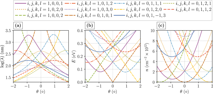
Using geometrical considerations explained in the main text we are able to relate the theoretical prediction of the super-moiré harmonics to real-space periods, reconstruction energies or densities. Different combinations of moiré vectors give more harmonics in addition to the harmonics already defined in Eq. (3). In Fig. S1, panels (a-c) period, reconstruction energy, and density are shown for different harmonics that appear in the low energy spectrum (lower than eV). Experimental results are obtained mostly as a function of carrier density, so panel S1(c) can be particularly important for extracting the expected values of the rotation angles, and the period of the underlying periodicities from the super-moiré features.
S2 Band structure - comparison with aligned bilayer
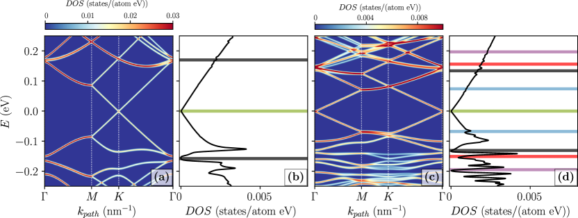
By solving the Diophantine equation from Eq. (7), commensurate structures that allow to define a unit cell can be obtained. One of the solutions is for rotations (aligned hBN) and (rotated hBN) resulting in the super-moiré period of nm. Figure S2 shows the band structure along the path in the SM mini-Brillouin zone and the DOS for a bilayer (aligned hBN/gr ) and trilayer hBN/gr/hBN ( and ), respectively.
In the bilayer case (Figs. S2(a, b)), the hBN substrate induces a pair of secondary Dirac points at energies meV, with large degree of electron-hole asymmetry which was discussed previously (at energies marked by black line), where is the (primary) Dirac point of graphene (marked by green line).The additional top hBN layer (Figs. S2(c, d)), as suggested from the other spectral calculations, results in additional Dirac-like points (marked by blue line in the DOS) at energies below the ones induced by aligned or rotated 2 layer moiré patterns ( meV). Additional secondary Dirac point due to the rotated hBN/gr appears as well (marked by red line).
The Dirac point in graphene is located at different points in the moiré or super-moiré mini-Brillouin zone, which is caused by different superlattice band folding [37].
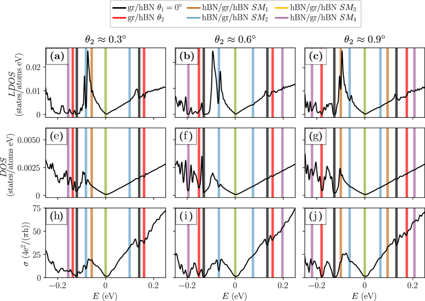
S3 Behaviour at higher rotation angles
To expand the discussion on the SM reconstruction effects, in Fig. 4 LDOS (at the same graphene site as in Fig. 4(b), panels S3(a-c)), DOS (panels S3(e-g)) and conductivity (panels S3(h-j)) are shown in a system with rotation angles and , , . The fits of the SM effects are marked with coloured stripes, where the different harmonics are labeled in the legend. Notice that the effects of the SM are more apparent in the LDOS when compared to global properties like DOS and conductivity, where the effects are averaged over different stacking regions. The SM features are almost completely wiped out at rotation , which confirms our findings about the necessity of close alignment of the layers in order to see the SM effects.