Manipulation of optomechanically induced transparency and absorption by indirectly coupling to an auxiliary cavity mode
Abstract
We theoretically study the optomechanically induced transparency (OMIT) and absorption (OMIA) phenomena in a single microcavity optomechanical system, assisted by an indirectly-coupled auxiliary cavity mode. We show that the interference effect between the two optical modes plays an important role and can be used to control the multiple-pathway induced destructive or constructive interference effect. The three-pathway interference could induce an absorption dip within the transparent window in the red sideband driving regime, while we can switch back and forth between OMIT and OMIA with the four-pathway interference. The conversion between the transparency peak and absorption dip can be achieved by tuning the relative amplitude and phase of the multiple light paths interference. Our system proposes a new platform to realize multiple pathways induced transparency and absorption in a single microcavity and a feasible way for realizing all-optical information processing.
pacs:
Valid PACS appear hereI Introduction
In the past decades, electromagnetically induced transparency (EIT) has been studied both theoretically and experimentally marangos1998electromagnetically ; kash1999ultraslow ; fleischhauer2005electromagnetically . And the potential applications range from ultraslow light propagation kash1999ultraslow , quantum information storage phillips2001storage ; liu2001observation to the enhancement of nonlinear processes (harris1990nonlinear, ; jain1996efficient, ). Normally, EIT is a coherent phenomenon due to the destructive quantum interference of two excitation pathways in a three-level system. On the other hand, the electromagnetically induced absorption (EIA) lezama1999electromagnetically ; taichenachev1999electromagnetically is the result of constructive interference between different pathways. Recently, the EIT effects are widely studied in the optical microresonators armani2003ultra ; jing2018nanoparticle ; liu2018gain ; liu2017controllable , i.e. the so called EIT-like effect totsuka2007slow ; yanik2004stopping ; xu2006experimental ; xiao2009electromagnetically ; zhou2011coherent ; dong2009modified ; peng2014and ; wang2016coupled-mode ; naweed2005induced ; wang2019multiple ; xiao2013tunneling ; li2016optomechanically ; huang2014electromagnetically ; yang2015coupled-mode-induced . Usually, this effect can be generated through a high quality factor (Q) cavity mode directly or indirectly coupling to a low Q one. In this case, a sharp transparent window at their original resonant frequency region appears when the two modes are frequency overlapped.
Based on the strong optical and mechanical interaction, optomechanical systems have potential applications in the fundamental research aspelmeyer2014cavity ; pikovski2012probing ; liu2018chiral ; liu2018observation ; chen2017high ; cai2017second ; xiong2018analysis ; abughanem2018cavity ; tian2019finite and provide a promising platform for exploring quantum nonlinear phenomena jiao2018optomechanical ; jiao2016nonlinear , such as ground state cooling arcizet2006radiation ; marquardt2007quantum ; wilson2007theory ; chan2011laser ; park2009resolved ; liu2013dynamic ; al2018ground ; jing2017high , entanglement in cavity optomechanical system wang2013reservoir ; palomaki2013entangling ; liao2014entangling . Meanwhile, the cavity optomechanics could enable the exploration of a variety of optical processes. The system has been studied and applied in OMIT Weis1520 ; xiong2018fundamentals ; kronwald2013optomechanically ; safavi2011electromagnetically ; lemonde2013nonlinear ; kim2015non ; shen2016experimental ; dong2015brillouin ; zhang2018loss ; lu2018optomechanically ; jing2015optomechanically , OMIA safavi2011electromagnetically ; qu2013phonon ; hocke2012electromechanically , quantum information processing stannigel2012optomechanical ; dong2012optomechanical ; lu2015squeezed and amplification nunnenkamp2014quantum ; li2017optical ; lu2019selective .
Analog to the EIT (EIA) in the atomic system, the OMIT (OMIA) effect is the result of destructive (constructive) interference between different pathways in optomechanical system. The OMIT effect has been investigated both theoretically and experimentally Weis1520 ; xiong2018fundamentals ; kronwald2013optomechanically ; safavi2011electromagnetically ; lemonde2013nonlinear ; kim2015non ; shen2016experimental ; dong2015brillouin ; jiang2015chip ; lu2017optomechanically . Compared with OMIT, the OMIA system generally consists of more degrees of freedom or more than two transition pathways for the probe qu2013phonon ; lei2015three ; ma2014tunable ; jiang2016phase ; hou2015optomechanically ; bai2016tunable ; si2017optomechanically ; zhang2017optomechanically ; liu2017controllable ; ullah2018multiple . The OMIT could be switched to OMIA through multiple-pathway interference effects, accomplished by coupling to an additional microcavity or adding more mechanical resonators. However, these approaches make the system more complicated and fragile to control.
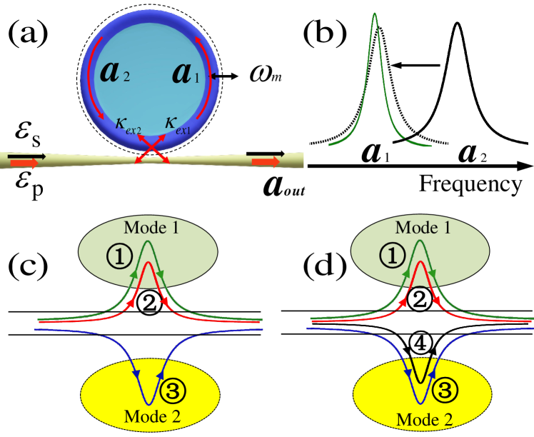
In this paper, we study the optomechanical system and multiple-pathway interference in a single microcavity, in which one cavity optical mode indirectly couples to an auxiliary cavity mode. As shown schematically in Fig.1, the optomechanical system contains two optical modes and one mechanical mode. The auxiliary cavity mode is adjacent to the dominant optical mode in frequency domain and can be tuned to overlap with xiao2009electromagnetically . Different from the directly coupled cavity case lei2015three ; hou2015optomechanically , the two optical modes here have no direct couple. The interference effect between the two optical modes are mediated by the tapered fiber and could induce the EIT-like phenomenon without the optomechancial interaction. Combining the EIT-like and OMIT effect, we can easily realize multiple-pathway interference. When the auxiliary cavity mode decouples to the phonons, the three-pathway interference will induce constructive interference effect. We find in the red sideband driving regime, the transmission rate of the system is sensitive to the auxiliary cavity mode. While the auxiliary cavity mode couples to the mechanical mode, the four-pathway interference could induce destructive or constructive interference effect. And the bi-directional transformations between OMIT and OMIA can be achieved. We also study the transmission of the three-pathway interference case in the blue sideband regime. The optical amplification mainly depends on the optomechanical gain and could enhanced by the auxiliary cavity mode. Therefore, the output spectrum can be precisely controlled by tuning the auxiliary cavity mode and the optomechanical coupling strength. The paper is organized as follows. In Sec II, we introduce the theoretical model of the optomechanical system shown in Fig.1. In Sec III, we study the physical origins of the three light propagation paths when the auxiliary cavity mode decouples to the mechanical mode. And we discuss the optical response of probe field both in red and blue sideband driving regime. In Sec IV, the bi-directional conversion between OMIT and OMIA can be achieved through the four-pathway interference effect. In Sec V, the conclusion is given.
II Model
As schematically shown in Fig.1, the system we considered here is a whispering-gallery-mode optomechanical microresonator, where two optical modes and one mechanical mode have been excited. The dominant optical mode has the resonant frequency and the internal loss . The auxiliary cavity mode has the resonant frequency and the internal loss . The mechanical resonator has the frequency with the effective mass . The optical modes and are two independent WGMs. However, the cavity mode can couple to the mode indirectly through the waveguide xiao2009electromagnetically . The interference between the two optical pathways results in EIT-like line shape. Both optical modes could couple to the mechanical resonator with different optomechanical coupling rate and . As shown in Fig.1 (c) and (d), the optomechanical coupling strength between the auxiliary cavity mode and the mechancial mode is weak. When the optomechanical coupling can be ignored, the system shows three pathways interference. Without loss of generality, the system shows four pathways interference when both optical modes couple to the mechanical mode. The Hamiltonian can be described as
| (1) |
where the operators and represent the position and momentum of the mechanical mode, respectively. The annihilation operator indicates the waveguide mode, which satisfies . (j=1,2) describes the coupling constant between the cavity mode and waveguide modes. The first four terms represent the free Hamiltonians of the optical and mechanical modes. The fifth term is to describe the Hamiltonian of the waveguide modes. And the last term indicates the the coupling between the optical modes and the waveguide modes. In our scheme, the system is driven by a strong control laser field with the amplitudes and frequency , respectively. Meanwhile, a weak probe laser field, with the amplitude and the frequency , is applied on the system. The dynamics of the optomechanical system can thus be described in the rotating frame at the pump frequency
| (2) | ||||
| (3) | ||||
| (4) | ||||
| (5) |
where and represent the detuings of optical modes with respect to the driving field. indicates the total decay rate of optical mode (j=1,2). is the frequency detuning between the probe field and the control field. And () is the external noise of the optical mode () introduced by the waveguide. is the thermal noise of the mechanical oscillator and is the decay rate of the mechanical mode. In our case, the pump laser field is much stronger than the probe field. By using the linearization approach, thus the Heisenberg operators can be divided into the steady parts and the fluctuation ones, i.e., (j = 1,2) and . Substituting the division forms into Eq.(2)-(5), the steady solutions of the above dynamical equations can be obtained as
| (6) | ||||
| (7) | ||||
| (8) |
Then, we only keep the first-order terms in the small fluctuation ones , , , and . Under these conditions, we can obtain the linearized Langevin equations as follows:
| (9) | ||||
| (10) | ||||
| (11) | ||||
| (12) | ||||
| (13) |
where and denote the effective detuning between the cavity modes and the control laser beam, including the frequency shift caused by the mechanical motion.
Combining the above analysis and Fig.1 (c) and (d), we can better understand the multiple light paths for interference. Fig.1 displays a schematic of quantum interference between different light paths. The photons at the output port could come from four different path. The different paths are: ① the probe photons excite the cavity mode and pass to the output port; ② the photons generated by the sideband transition through the optomechanical interaction in mode are coupled out the cavity through the waveguide; ③ the probe field passes through the cavity mode directly. In our case, the system only shows three different pathways when the optomechanical coupling rate can be neglected. Otherwise, the fourth pathway is: ④ the photons genetated by anti-Stokes process in the optical mode are coupled out the cavity through the waveguide. Thus the photons in the output beam is the sum of four different paths. For convenience, we introduce and to get the transmission of the system, where is the zero point fluctuation. We also neglect the quantum noise , and . Without loss of generality, in the following discussions the frequency of the auxiliary cavity mode is tuned to satisfy . According to the input-output theorygardiner2004quantum , we can get the output of the probe field: . With neglecting the high order sideband effect, the normalized transmission coefficient in the red sideband driving regime can be simplified to
| (14) |
where and are the effective optomechanical coupling strength, , and . When the system is driven by the blue-detuned pump field, the normalized transmission coefficient is
| (15) |
where , and . And the corresponding power transmission coefficient is given by
III Transmission rate with three pathways interference
Before we discuss the three-pathway interference effect, the two-pathway induced EIT-like effect is considered. The all-optical analogues of the EIT effect are widely studied in optical resonators systems. And this EIT-like effect contains two coupling mechanism: directly coupled-resonator-induced transparency(DCRIT) totsuka2007slow ; yanik2004stopping and indirectly coupled-resonator-induced transparency(ICRIT) xiao2009electromagnetically ; dong2009modified . By combining the DCRIT and OMIT effect, the three-pathway induced EIT and EIA effects has been studied in different system lei2015three ; bai2016tunable ; si2017optomechanically ; zhang2017optomechanically ; liu2017controllable . For the coupled cavity system, the two cavities should be tuned precisely to couple, requiring the complicated control and fabrication for the expereimtns. Thus here we study the three-pathway interference effect by combining the ICRIT effect and optomechanical interaction in a single cavity. In this section, we consider the situation that the auxiliary cavity mode decouples to the mechanical mode, i.e., . We study the power transmission coefficient with the effect of the auxiliary cavity mode both in the red and blue sideband driving regime. We find that the three mode interaction could be tuned by mode , which can be used to control the transmission rate.
III.1 Three-pathway interference with red-detuned driving
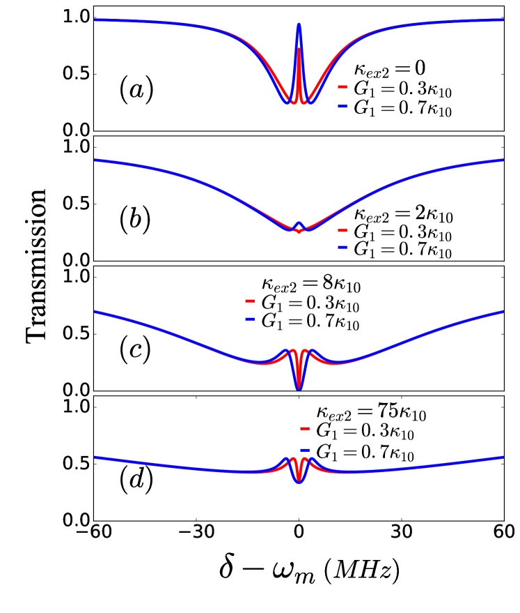
We have discussed the physical origins of the three pathway interference phenomena in Fig.1 (c). The photons at the output port with frequency equaling to the probe signal come from the three pathways. When one light path is changed, the relative amplitude and phase of the multiple light paths interference is adjusted. This influence of the three-pathway interference effect will change the output spectrum. To investigate the influence of path ③ on the three-pathway interference effect, we plot the output spectrum in Fig.2 with different external coupling rate . In Fig.2 (a), the transmission shows the OMIT window without the auxiliary mode. This is the result of the two-pathway destructive interference effect. When the optical mode couples with tapered fiber, the transparent peak maintains but becomes really minute plotted by blue line (@ ) in (b). While the absorption dip starts appearing represent by the red solid line with the weaker optomechanical coupling rate MHz.
Further increasing the external coupling rate of the auxiliary mode to 40 MHz in Fig.2 (c), the output spectra show the evident absorption dips within a EIT-like window for both lines. The power transmission drops to zero due to the constructive interference. By tuning the external coupling rate to , the tapered fiber mediated interference
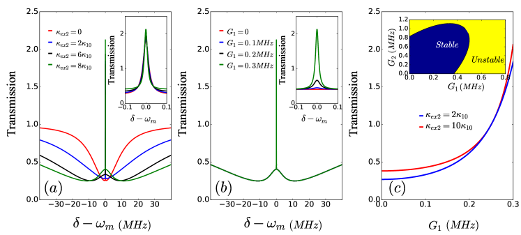
effect is strong compared with the optomechanical coupling strength. Both the transmission spectrum and the absorption window become wider. While the transmission () increases to 0.33 even with the absorption dip.
Form Fig.2, we can obtain that the interference between the two optical modes could lead the transmission rate form OMIT peak to OMIA dip. The reason for the absorption windows is the constructive interference effect induced by the auxiliary cavity mode. Without the auxiliary cavity mode , the output field only connects with mode and shows a OMIT peak in Fig.2 (a). When the auxiliary cavity mode is introduced, the photons with frequency equaling to the probe signal come from the optical modes and both. While the anti-stokes process leads to destructive interference for the intracavity field , suppressing the photons population of . The constructive interference leads an absorption dip and the transmission rate of central dip drops to zero.
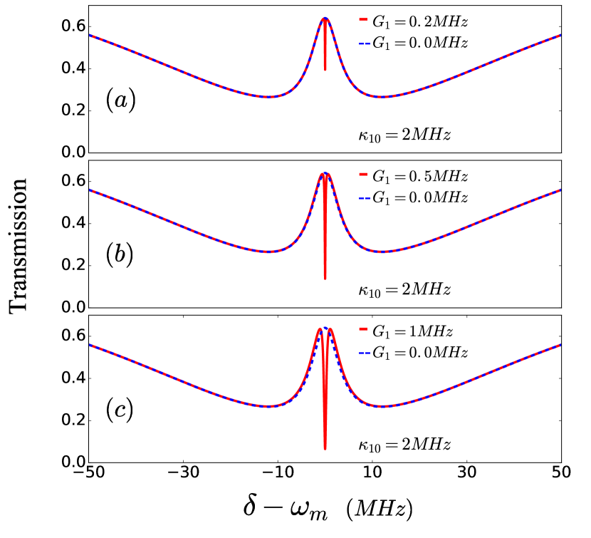
Then we study the influence of the optomechanical interaction on the three-pathway interference. The transmission rate is plotted in Fig.3 with the different optomechanical coupling strength . In Fig.3 (a), (b) and (c), the external coupling strength is fixed to 60 MHz and . The transmission displays the EIT-like window with plotted by the blue dashed lines. When the optomechanical coupling strength is increased to 0.4 MHz , there is an small absorption window within the EIT window in Fig.3 (a). In Fig.3(c), the transmission of the central dip drops to 0.1 with stronger optomechanical coupling rate . It is obvious that with increasing the optomechanical coupling rate, the transmission shows more prominent absorption effect.
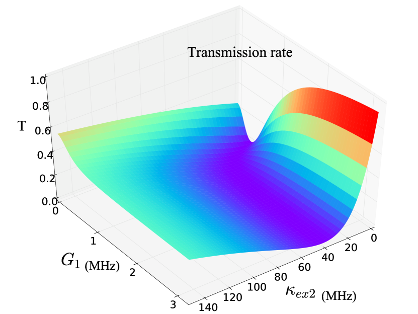
From the Fig.2 and Fig.3, we can obtain that the three-pathway interference effect could vary from the transparent window to an absorption dip in our system. The output spectrum is sensitive to the auxiliary cavity mode in Fig.2, which can be used to control the three mode interaction. While in Fig.3, the depth of the absorption dip can be manipilated by the path ②. This system offers two effective methods to tune the optical response. The transmission is plotted in Fig.4 as the function of the optomechanical coupling rate and the external coupling strength of the auxiliary cavity mode. It can be obtained that with the weak optomechanical coupling rate, the effect of two optical modes interference becomes more evident and leads to transparency-like window. While the transmission shows OMIT window when is weak. Thus the transmission can be manipulated through tuning the relative amplitudes and phases of the three-pathway interference.
III.2 Three-pathway induced amplification with blue-detuned driving
In our system, the photons generated form the optomechanical interaction will directly affect the intracavity probe photons population, which could result in OMIA dip in the red sideband pumping regime. Now we consider the situation that the system is driven by a blue-detuned driving field and the auxiliary optical mode decouples to the mechanical mode. In this scheme we limit our parameters to the stable driving regime. And the stability condition can be obtained by analyzing the Lyapunov exponents benettin1980lyapunov of the Jacobian matrix. We have plotted the border between the stable and unstable condition in the inset of Fig.5(c). In Fig.5, we have shown the the normalized output spectra of optomechanical system with a blue-detuned pump field. In Fig.5 (a), we plot the transmission rate as a function of for different values of external coupling rate . The red solid line indicates the transmission with optomechanical coupling rate MHz while . Without the auxiliary optical mode, it is clear that the transmission line shows an amplified peak. With the enhancement of the two optical mode interference through increasing , the transmission becomes broader and shows the EIT-like window. As the inset of Fig.5 (a) shows, the transmission at the central peak could enhanced with stronger external coupling strength of the auxiliary optical mode.
We also plot the transmission amplification effect for different values of the coupling strength in Fig.5 (b). Here is fixed to 60 MHz, and is increased to 0.3 MHz. The red solid line shows a EIT-like window without optomechanical interaction. It is clear that the transmission rate of central peak increases to 1.75 with MHz compared with red line. In Fig.5(b), the transmission amplification effect of the probe field becomes stronger with increasing the optomechanical coupling rate . Fig.5 (c) plots the transmission rate of the central peak as a function of the coupling rate when the probe frequency detuning . The blue (red) solid line plots the amplification effect when equals to 10 (60) MHz. When is small, the fiber mediated two optical interference is strong, the transmission rate depends on . For strong optomechanical coupling rate, the amplification depends on , while the transmission can be affected by the auxiliary cavity mode.
By increasing the optomechancial coupling rate , the stokes process is enhanced and emits photons and phonons. The photons generated by the optomechanical interaction are degenerate with the probe field, which accelerates the circulating power of . The two optical interference is weak compared with the optomechanical coupling. Thus the optomechanical amplification plays a dominant role in the three pathways. The closer to the stability border, the more prominent the optomechanical gain effect is. However, even the central peak is not sensitive to , the amplification effect could be enhanced by the two optical interference.
IV Transmission rate with four-pathway interference effect
In this section, we will consider the situation that the auxiliary cavity mode couples to the mechanical mode. Here we assume that the effective optomechanical coupling strength and can be tuned separately by using the extra tapered fiber to introduce the extra pump field.
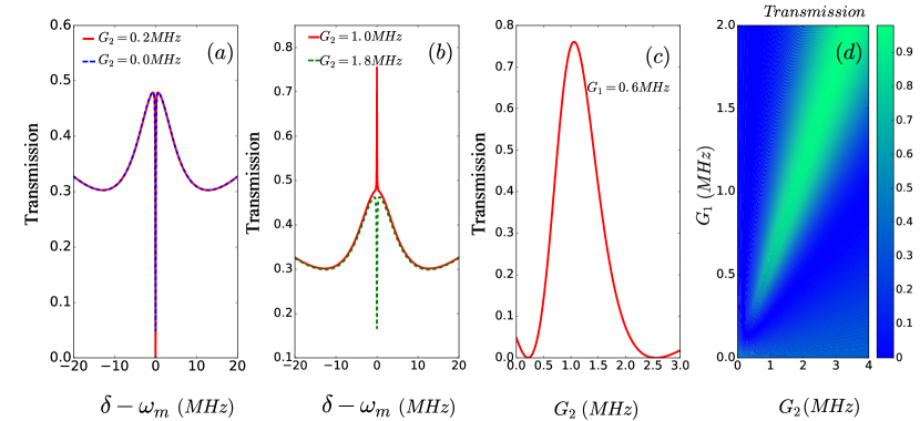
To investigate the effect of optomechanical coupling rate , on the transmission spectrum, we plot the transmission with the different optomechanical couping rates and in Fig.6 with the red-detuned driving. Under the three pathways situation in red sideband regime, the transmission rates show an absorption window, which have been presented in Fig.2. Through increasing the optomechanical coupling rate , the absorption dip becomes deeper and wider. Different with three pathways induced absorption, four pathways interference effect can switch the transmission spectrum back and forth between OMIT and OMIA depending on the coupling strength and . In Fig.6(a), when , the transmission of the central dip is 0.13 which has been presented by the blue dashed line. While the absorption dip becomes more evident in the middle of transmission window when MHz and MHz. The transmission drops to 0 due to constructive interference effect. By keeping MHz unchanged, the transmission rate is plotted in Fig.6(b) when the coupling rate is enlarged to 1 MHz. In contrast to the absorption dip for the coupling rate MHz, here the OMIT peak appears for the resonant case, making the transmission go up to 0.75. By increasing the coupling rate to 1.8 MHz, the constructive interference between different pathways results in the OMIA again. To show the manipulation between OMIA and OMIT through tuning the ratio between and , the height of the central peak is plotted in Fig.6(c). It is clear that when the optomechanical coupling strength is weak, the four-pathway interference will enhance the constructive interference and lead to the OMIA effect. Further increasing , the four pathways will result in the destructive interference and OMIT window. While is larger than 1.5 MHz, the constructive interference occurs, resulting in the absorption window again. In Fig.6(d), we plot the transmission rate as a function of different coupling rate and . We can obtain that the conversion between the constructive and destructive interference can be achieved by tuning the coupling strength of and . Compared with when the coupling rate , transmission can be switched to 0 or 1 due to the OMIA or OMIT effect.
V Conclusion
In summary, we have explored an optomechanical system with multiple light paths interference effect in a single optical resonator. We give the explicit physical explanations and detailed calculations in this paper. By combining the EIT-like and OMIT effect, the system shows destructive or constructive interference effect under different conditions. The auxiliary cavity mode offers the additional light pathway to control the output spectrum. Through enhancing the optomechanical coupling strength or the external coupling rate of the auxiliary cavity mode, we can tune the optical response of the probe field effectively. Experimentally, the system has no limitation on the quality factor of the auxiliary cavity mode, making it easy to implement. Moreover, our model paves an easy way for realization of multiple interference and manipulation of OMIT and OMIA.
Acknowledgments
The work was supported by the National Natural Science Foundation of China (NSFC) (20171311628); Ministry of Science and Technology of the People’s Republic of China (MOST) (2017YFA0303700); Beijing Advanced Innovation Center for Future Chip (ICFC).
References
- [1] Jonathan P Marangos. Electromagnetically induced transparency. Journal of Modern Optics, 45(3):471–503, 1998.
- [2] Michael M Kash, Vladimir A Sautenkov, Alexander S Zibrov, Leo Hollberg, George R Welch, Mikhail D Lukin, Yuri Rostovtsev, Edward S Fry, and Marlan O Scully. Ultraslow group velocity and enhanced nonlinear optical effects in a coherently driven hot atomic gas. Physical Review Letters, 82(26):5229, 1999.
- [3] Michael Fleischhauer, Atac Imamoglu, and Jonathan P Marangos. Electromagnetically induced transparency: Optics in coherent media. Reviews of modern physics, 77(2):633, 2005.
- [4] DF Phillips, A Fleischhauer, A Mair, RL Walsworth, and Mikhail D Lukin. Storage of light in atomic vapor. Physical Review Letters, 86(5):783, 2001.
- [5] Chien Liu, Zachary Dutton, Cyrus H Behroozi, and Lene Vestergaard Hau. Observation of coherent optical information storage in an atomic medium using halted light pulses. Nature, 409(6819):490, 2001.
- [6] Stephen E Harris, JE Field, and A Imamoğlu. Nonlinear optical processes using electromagnetically induced transparency. Physical Review Letters, 64(10):1107, 1990.
- [7] Maneesh Jain, Hui Xia, GY Yin, AJ Merriam, and SE Harris. Efficient nonlinear frequency conversion with maximal atomic coherence. Physical review letters, 77(21):4326, 1996.
- [8] A Lezama, S Barreiro, and AM Akulshin. Electromagnetically induced absorption. Physical Review A, 59(6):4732, 1999.
- [9] AV Taichenachev, AM Tumaikin, and VI Yudin. Electromagnetically induced absorption in a four-state system. Physical Review A, 61(1):011802, 1999.
- [10] DK Armani, TJ Kippenberg, SM Spillane, and KJ Vahala. Ultra-high-q toroid microcavity on a chip. Nature, 421(6926):925, 2003.
- [11] Hui Jing, H Lü, SK Özdemir, T Carmon, and Franco Nori. Nanoparticle sensing with a spinning resonator. Optica, 5(11):1424–1430, 2018.
- [12] Xiao-Fei Liu, Fuchuan Lei, Tie-Jun Wang, Gui-Lu Long, and Chuan Wang. Gain lifetime characterization through time-resolved stimulated emission in a whispering-gallery mode microresonator. Nanophotonics, 8(1):127–134, 2018.
- [13] Yu-Long Liu, Rebing Wu, Jing Zhang, Şahin Kaya Özdemir, Lan Yang, Franco Nori, and Yu-xi Liu. Controllable optical response by modifying the gain and loss of a mechanical resonator and cavity mode in an optomechanical system. Physical Review A, 95(1):013843, 2017.
- [14] Kouki Totsuka, Norihiko Kobayashi, and Makoto Tomita. Slow light in coupled-resonator-induced transparency. Physical review letters, 98(21):213904, 2007.
- [15] Mehmet Fatih Yanik, Wonjoo Suh, Zheng Wang, and Shanhui Fan. Stopping light in a waveguide with an all-optical analog of electromagnetically induced transparency. Physical Review Letters, 93(23):233903, 2004.
- [16] Qianfan Xu, Sunil Sandhu, Michelle L Povinelli, Jagat Shakya, Shanhui Fan, and Michal Lipson. Experimental realization of an on-chip all-optical analogue to electromagnetically induced transparency. Physical Review Letters, 96(12):123901, 2006.
- [17] Yunfeng Xiao, Lina He, Jiangang Zhu, and Lan Yang. Electromagnetically induced transparency-like effect in a single polydimethylsiloxane-coated silica microtoroid. Applied Physics Letters, 94(23):231115, 2009.
- [18] Linjie Zhou, Tong Ye, and Jianping Chen. Coherent interference induced transparency in self-coupled optical waveguide-based resonators. Optics Letters, 36(1):13–15, 2011.
- [19] Chun-Hua Dong, Chang-Ling Zou, Yun-Feng Xiao, Jin-Ming Cui, Zheng-Fu Han, and Guang-Can Guo. Modified transmission spectrum induced by two-mode interference in a single silica microsphere. Journal of Physics B: Atomic, Molecular and Optical Physics, 42(21):215401, 2009.
- [20] Bo Peng, Şahin Kaya Özdemir, Weijian Chen, Franco Nori, and Lan Yang. What is and what is not electromagnetically induced transparency in whispering-gallery microcavities. Nature communications, 5:5082, 2014.
- [21] Yue Wang, Kun Zhang, Song Zhou, Yihui Wu, Mingbo Chi, and Peng Hao. Coupled-mode induced transparency in a bottle whispering-gallery-mode resonator. Optics Letters, 41(8):1825–1828, 2016.
- [22] Ahmer Naweed, G Farca, Siyka I Shopova, and A T Rosenberger. Induced transparency and absorption in coupled whispering-gallery microresonators. Physical Review A, 71(4):043804, 2005.
- [23] Tao Wang, Yun-Qi Hu, Chun-Guang Du, and Gui-Lu Long. Multiple eit and eia in optical microresonators. Optics express, 27(5):7344–7353, 2019.
- [24] Yun-Feng Xiao, Xue-Feng Jiang, Qi-Fan Yang, Li Wang, Kebin Shi, Yan Li, and Qihuang Gong. Tunneling-induced transparency in a chaotic microcavity. Laser & Photonics Reviews, 7(5):L51–L54, 2013.
- [25] Guanyu Li, Xiaoshun Jiang, Shiyue Hua, Yingchun Qin, and Min Xiao. Optomechanically tuned electromagnetically induced transparency-like effect in coupled optical microcavities. Applied Physics Letters, 109(26):261106, 2016.
- [26] Qingzhong Huang, Zhan Shu, Ge Song, Juguang Chen, Jinsong Xia, and Jinzhong Yu. Electromagnetically induced transparency-like effect in a two-bus waveguides coupled microdisk resonator. Optics Express, 22(3):3219–3227, 2014.
- [27] Yong Yang, Sunny Saurabh, Jonathan M Ward, and Sile Nic Chormaic. Coupled-mode-induced transparency in aerostatically tuned microbubble whispering-gallery resonators. Optics Letters, 40(8):1834–1837, 2015.
- [28] Markus Aspelmeyer, Tobias J Kippenberg, and Florian Marquardt. Cavity optomechanics. Reviews of Modern Physics, 86(4):1391, 2014.
- [29] Igor Pikovski, Michael R Vanner, Markus Aspelmeyer, MS Kim, and Časlav Brukner. Probing planck-scale physics with quantum optics. Nature Physics, 8(5):393, 2012.
- [30] Xiao-Fei Liu, Tie-Jun Wang, Yong-Pan Gao, Cong Cao, and Chuan Wang. Chiral microresonator assisted by rydberg-atom ensembles. Physical Review A, 98(3):033824, 2018.
- [31] Yanzhong Liu, Tengfei Hao, Wei Li, Jose Capmany, Ninghua Zhu, and Ming Li. Observation of parity-time symmetry in microwave photonics. Light: Science & Applications, 7(1):38, 2018.
- [32] Xu Chen, Clément Chardin, Kevin Makles, Charles Caër, Sheon Chua, Rémy Braive, Isabelle Robert-Philip, Tristan Briant, Pierre-François Cohadon, Antoine Heidmann, et al. High-finesse fabry–perot cavities with bidimensional si 3 n 4 photonic-crystal slabs. Light: Science & Applications, 6(1):e16190, 2017.
- [33] Kang Cai, RuiXia Wang, ZhangQi Yin, and GuiLu Long. Second-order magnetic field gradient-induced strong coupling between nitrogen-vacancy centers and a mechanical oscillator. SCIENCE CHINA Physics, Mechanics & Astronomy, 60(7):070311, 2017.
- [34] Xiao-Ran Xiong, Yong-Pan Gao, Xiao-Fei Liu, Cong Cao, Tie-Jun Wang, and Chuan Wang. The analysis of high-order sideband signals in optomechanical system. SCIENCE CHINA Physics, Mechanics & Astronomy, 61(9):090322, 2018.
- [35] M AbuGhanem, AH Homid, and M Abdel-Aty. Cavity control as a new quantum algorithms implementation treatment. Frontiers of Physics, 13(1):130303, 2018.
- [36] Meng Tian, Yong-Gang Huang, Sha-Sha Wen, Hong Yang, Xiao-Yun Wang, Jin-Zhang Peng, and He-Ping Zhao. Finite-element method for obtaining the regularized photon green function in lossy material. EPL (Europhysics Letters), 126(1):13001, 2019.
- [37] Ya-Feng Jiao, Tian-Xiang Lu, and Hui Jing. Optomechanical second-order sidebands and group delays in a kerr resonator. Physical Review A, 97(1):013843, 2018.
- [38] Y Jiao, H Lü, J Qian, Y Li, and H Jing. Nonlinear optomechanics with gain and loss: amplifying higher-order sideband and group delay. New Journal of Physics, 18(8):083034, 2016.
- [39] Olivier Arcizet, P-F Cohadon, Tristan Briant, Michel Pinard, and Antoine Heidmann. Radiation-pressure cooling and optomechanical instability of a micromirror. Nature, 444(7115):71, 2006.
- [40] Florian Marquardt, Joe P Chen, Aashish A Clerk, and SM Girvin. Quantum theory of cavity-assisted sideband cooling of mechanical motion. Physical review letters, 99(9):093902, 2007.
- [41] Ignacio Wilson-Rae, Nima Nooshi, W Zwerger, and Tobias J Kippenberg. Theory of ground state cooling of a mechanical oscillator using dynamical backaction. Physical Review Letters, 99(9):093901, 2007.
- [42] Jasper Chan, TP Mayer Alegre, Amir H Safavi-Naeini, Jeff T Hill, Alex Krause, Simon Gröblacher, Markus Aspelmeyer, and Oskar Painter. Laser cooling of a nanomechanical oscillator into its quantum ground state. Nature, 478(7367):89, 2011.
- [43] Young-Shin Park and Hailin Wang. Resolved-sideband and cryogenic cooling of an optomechanical resonator. Nature physics, 5(7):489, 2009.
- [44] Yong-Chun Liu, Yun-Feng Xiao, Xingsheng Luan, and Chee Wei Wong. Dynamic dissipative cooling of a mechanical resonator in strong coupling optomechanics. Physical review letters, 110(15):153606, 2013.
- [45] Saud Al-Awfi, Mohannad Al-Hmoud, and Smail Bougouffa. Ground-state cooling in cavity optomechanics with unresolved sidebands. EPL (Europhysics Letters), 123(1):14005, 2018.
- [46] H Jing, ŞK Özdemir, H Lü, and Franco Nori. High-order exceptional points in optomechanics. Scientific reports, 7(1):3386, 2017.
- [47] Ying-Dan Wang and Aashish A Clerk. Reservoir-engineered entanglement in optomechanical systems. Physical review letters, 110(25):253601, 2013.
- [48] TA Palomaki, JD Teufel, RW Simmonds, and KW Lehnert. Entangling mechanical motion with microwave fields. Science, 342(6159):710–713, 2013.
- [49] Jie-Qiao Liao, Qin-Qin Wu, Franco Nori, et al. Entangling two macroscopic mechanical mirrors in a two-cavity optomechanical system. Physical Review A, 89(1):014302, 2014.
- [50] Stefan Weis, Rémi Rivière, Samuel Deléglise, Emanuel Gavartin, Olivier Arcizet, Albert Schliesser, and Tobias J. Kippenberg. Optomechanically induced transparency. Science, 330(6010):1520–1523, 2010.
- [51] Hao Xiong and Ying Wu. Fundamentals and applications of optomechanically induced transparency. Applied physics reviews, 5(3):031305, 2018.
- [52] Andreas Kronwald and Florian Marquardt. Optomechanically induced transparency in the nonlinear quantum regime. Physical review letters, 111(13):133601, 2013.
- [53] Amir H Safavi-Naeini, TP Mayer Alegre, Jasper Chan, Matt Eichenfield, Martin Winger, Qiang Lin, Jeff T Hill, Darrick E Chang, and Oskar Painter. Electromagnetically induced transparency and slow light with optomechanics. Nature, 472(7341):69, 2011.
- [54] Marc-Antoine Lemonde, Nicolas Didier, and Aashish A Clerk. Nonlinear interaction effects in a strongly driven optomechanical cavity. Physical review letters, 111(5):053602, 2013.
- [55] JunHwan Kim, Mark C Kuzyk, Kewen Han, Hailin Wang, and Gaurav Bahl. Non-reciprocal brillouin scattering induced transparency. Nature Physics, 11(3):275, 2015.
- [56] Zhen Shen, Yan-Lei Zhang, Yuan Chen, Chang-Ling Zou, Yun-Feng Xiao, Xu-Bo Zou, Fang-Wen Sun, Guang-Can Guo, and Chun-Hua Dong. Experimental realization of optomechanically induced non-reciprocity. Nature Photonics, 10(10):657, 2016.
- [57] Chun-Hua Dong, Zhen Shen, Chang-Ling Zou, Yan-Lei Zhang, Wei Fu, and Guang-Can Guo. Brillouin-scattering-induced transparency and non-reciprocal light storage. Nature communications, 6:6193, 2015.
- [58] H Zhang, F Saif, Y Jiao, and Hui Jing. Loss-induced transparency in optomechanics. Optics express, 26(19):25199–25210, 2018.
- [59] Hao Lü, Changqing Wang, Lan Yang, and Hui Jing. Optomechanically induced transparency at exceptional points. Physical Review Applied, 10(1):014006, 2018.
- [60] H Jing, Şahin K Özdemir, Z Geng, Jing Zhang, Xin-You Lü, Bo Peng, Lan Yang, and Franco Nori. Optomechanically-induced transparency in parity-time-symmetric microresonators. Scientific reports, 5:9663, 2015.
- [61] Kenan Qu and GS Agarwal. Phonon-mediated electromagnetically induced absorption in hybrid opto-electromechanical systems. Physical Review A, 87(3):031802, 2013.
- [62] Fredrik Hocke, Xiaoqing Zhou, Albert Schliesser, Tobias J Kippenberg, Hans Huebl, and Rudolf Gross. Electromechanically induced absorption in a circuit nano-electromechanical system. New Journal of Physics, 14(12):123037, 2012.
- [63] K Stannigel, Peter Komar, SJM Habraken, SD Bennett, Mikhail D Lukin, P Zoller, and P Rabl. Optomechanical quantum information processing with photons and phonons. Physical review letters, 109(1):013603, 2012.
- [64] Chunhua Dong, Victor Fiore, Mark C Kuzyk, and Hailin Wang. Optomechanical dark mode. Science, 338(6114):1609–1613, 2012.
- [65] Xin-You Lü, Ying Wu, JR Johansson, Hui Jing, Jing Zhang, and Franco Nori. Squeezed optomechanics with phase-matched amplification and dissipation. Physical review letters, 114(9):093602, 2015.
- [66] Andreas Nunnenkamp, V Sudhir, AK Feofanov, A Roulet, and TJ Kippenberg. Quantum-limited amplification and parametric instability in the reversed dissipation regime of cavity optomechanics. Physical review letters, 113(2):023604, 2014.
- [67] Yong Li, YY Huang, XZ Zhang, and Lin Tian. Optical directional amplification in a three-mode optomechanical system. Optics express, 25(16):18907–18916, 2017.
- [68] Tian-Xiang Lu, Ya-Feng Jiao, Hui-Lai Zhang, Farhan Saif, and Hui Jing. Selective and switchable optical amplification with mechanical driven oscillators. Physical Review A, 100(1):013813, 2019.
- [69] Xuefeng Jiang, Min Wang, Mark C Kuzyk, Thein Oo, Gui-Lu Long, and Hailin Wang. Chip-based silica microspheres for cavity optomechanics. Optics express, 23(21):27260–27265, 2015.
- [70] Hao Lü, Yajing Jiang, Yu-Zhu Wang, and Hui Jing. Optomechanically induced transparency in a spinning resonator. Photonics Research, 5(4):367–371, 2017.
- [71] Fu-Chuan Lei, Ming Gao, Chunguang Du, Qing-Li Jing, and Gui-Lu Long. Three-pathway electromagnetically induced transparency in coupled-cavity optomechanical system. Optics express, 23(9):11508–11517, 2015.
- [72] Peng-Cheng Ma, Jian-Qi Zhang, Yin Xiao, Mang Feng, and Zhi-Ming Zhang. Tunable double optomechanically induced transparency in an optomechanical system. Physical Review A, 90(4):043825, 2014.
- [73] Cheng Jiang, Yuanshun Cui, Xintian Bian, Fen Zuo, Hualing Yu, and Guibin Chen. Phase-dependent multiple optomechanically induced absorption in multimode optomechanical systems with mechanical driving. Physical Review A, 94(2):023837, 2016.
- [74] BP Hou, LF Wei, and SJ Wang. Optomechanically induced transparency and absorption in hybridized optomechanical systems. Physical Review A, 92(3):033829, 2015.
- [75] C Bai, BP Hou, DG Lai, and D Wu. Tunable optomechanically induced transparency in double quadratically coupled optomechanical cavities within a common reservoir. Physical Review A, 93(4):043804, 2016.
- [76] Liu-Gang Si, Hao Xiong, M Suhail Zubairy, and Ying Wu. Optomechanically induced opacity and amplification in a quadratically coupled optomechanical system. Physical Review A, 95(3):033803, 2017.
- [77] XY Zhang, YQ Guo, P Pei, and XX Yi. Optomechanically induced absorption in parity-time-symmetric optomechanical systems. Physical Review A, 95(6):063825, 2017.
- [78] Kamran Ullah, Hui Jing, and Farhan Saif. Multiple electromechanically-induced-transparency windows and fano resonances in hybrid nano-electro-optomechanics. Physical Review A, 97(3):033812, 2018.
- [79] Crispin Gardiner and Peter Zoller. Quantum noise: a handbook of Markovian and non-Markovian quantum stochastic methods with applications to quantum optics, volume 56. Springer Science & Business Media, 2004.
- [80] Giancarlo Benettin, Luigi Galgani, Antonio Giorgilli, and Jean-Marie Strelcyn. Lyapunov characteristic exponents for smooth dynamical systems and for hamiltonian systems; a method for computing all of them. part 1: Theory. Meccanica, 15(1):9–20, 1980.