Tensor network strategies for calculating biexcitons and trions in monolayer 2D materials beyond the ground state
Abstract
Recently in [Phys. Rev. B 99, 241301(R) (2019)] tensor networks build upon logical circuits were briefly introduced to retrieve exciton and biexciton states. Compared to a conventional approach the tensor network methods scales logarithmic instead of linear in the grid points of the Brioullin zone and linear instead of exponential in the number of electrons and holes. This enables calculations with higher precision on the full Brioullin zone than previously possible. In this paper extensive details for an efficient implementation and the corresponding mathematical background are presented. In particular this includes applications and results for excitons, trions and biexcitons (for monolayer MoS2 as example), going beyond the initial brief introduction. Furthermore strategies for calculating selective excited bound states and tests of common approximations are discussed making use of the high accuracy full Brioullin zone treatment of the tensor network method.
I Introduction
Bound electron hole states such as exciton, trions and biexcitons have been in the focus of semiconductor research since decades Lindberg and Koch (1988); Butscher et al. (2005); Malić et al. (2008); Reiter et al. (2007); Schmidt et al. (2016); Chatterjee et al. (2004); Winzer et al. (2010); Meckbach et al. (2018). Recently interest was intensified due to the introduction of monolayer two dimensional materials such as transition metal dichalcogenides TMDCs, which show bound electron-hole complexes with very high binding energies Qiu et al. (2013a); Berghäuser and Malic (2014); Qiu et al. (2015). Excitons are routinely calculated in effective mass approximation Haug and Koch (2009); Hüser et al. (2013); Berghäuser and Malic (2014), but also on the full Brioullin zone with different accuracy Ridolfi et al. (2018); Deilmann and Thygesen (2019); Steinhoff et al. (2018a); Qiu et al. (2013a, 2015).
On the other hand calculations of bound electron hole complexes involving a higher number of particles such as trions, biexcitons or charged biexcitons remain sparse Stébé et al. (1997); Mayrock et al. (1999); Esser et al. (2000, 2001); Mostaani et al. (2017); Singh et al. (2016); Florian et al. (2018); Zhang et al. (2015); Kidd et al. (2016); Drüppel et al. (2017); Steinhoff et al. (2018b). Often the theoretical approach for larger complexes rely on approximations: effective mass approximation Stébé et al. (1997); Mayrock et al. (1999); Esser et al. (2000, 2001); Zhang et al. (2015), certain Ansatz functionsMayrock et al. (1999); Katsch et al. (2019) or restrict the calculation to a part of the Brioullin zone Steinhoff et al. (2018b). A high number of grid points is not feasible for numerical calculations for larger complexes. Main problem are that the many particle wave functions are high dimensional (grid points of the Brioullin zone) and high rank tensors leading to unfeasible memory and computational requirements.
In Kuhn and Richter (2019) it was briefly shown, that tensor network methods (including matrix product states Vidal (2003); Orús (2014); Schollwöck (2011); Cirac et al. (2017); Verstraete and Cirac (2006); Vidal (2007); Cirac et al. (2017); Clark et al. (2010), DMRG White (1992); Schollwöck (2011) and quantics tensor trains Oseledets (2009, 2010); Khoromskij (2011); Kazeev and Khoromskij (2012); Khoromskaia and Khoromskij (2015); Benner et al. (2017)) using logical circuits, can be used to calculate bound exciton and biexciton states on a Brioullin zone with a high number of grid points.
However the first introduction of the method in Ref. Kuhn and Richter, 2019 was targeted to general cluster/correlation expansion treatments and no discussion of the details and pitfalls for creating an efficient implementation were given. Furthermore strategies to selectively calculate a specific excited bound eigenstates are a missing ingredient, since most tensor network methods such as DMRG often retrieve only the ground state of the system and often the ground state is a rather uninteresting dark state.
Therefore this paper gives a very detailed introduction into the method specialized to wave functions of electron hole complexes. This includes also details of the best gauge for the encoding of band structure, tight binding coefficients and Coulomb coupling into the tensor network with logical circuits and also ideas for the transformation into matrix product operator (MPO) form are discussed. After a recapitulation of DMRG and imaginary time propagation as methods for retrieving eigenstates of the Hamilton operator, exciton, trion and biexciton eigenstates are calculated and discussed for a MoS2 monolayer material. Focus is on retrieving selected excited eigenstates beyond the ground state, accordingly coordinate transformations and projections into parts of the Brioullin zone applied directly on the tensor level are discussed as well as approaches for a faster calculation using imaginary time propagation. Readers only interested in physical results can skip to Sec. VII and following.
II Model system, Hamiltonian and generalized Wannier equation
The paper is focused on method development, a realistic but slightly simplified model is used with a similar complexity as the full system. The Hamiltonian for bound electron hole complexes in semiconductors includes the band structure and the Coulomb interaction . The electronic bandstructure reads:
| (1) |
where and are the creation and annihilation operators for an electron (conduction bands) or hole (valence bands) with the band index and the quasi momentum ). includes as a multiindex also the spin . For a valence band it holds as well as for the conduction band . Here represents the band structure for the respective carrier, where we restrict our discussion to the valence and conduction band (including spin, cf. Fig. 1) for the electron hole complexes. For the numerical results presented here, we use the tight binding bandstructure from Ridolfi et al. (2015, 2018). For the numerical calculation the quasi momentum is using the basis vectors and of the two dimensional Brioullin zone ( are not the Cartesian basis elements) with being integer numbers and the number of grid points in one dimension resulting in a Monkhorst-Pack grid. For the presented method, the quasi momentum is written using the bits of the integer numbers
| (2) |
is the number of bits per dimension and are integer numbers, that are used to shift the Brioullin zone grid, and will be beneficial for applications discussed later using the tensor representation. Furthermore note, that many properties of the semiconductor are periodic with respect to the reciprocal lattice vector , so that the index and label often the same quantity (valid e.g. for band structure tight-binding coefficients etc., not valid for Coulomb potential). The Coulomb interaction Hamiltonian reads:
| (3) |
is 1, if and are both electrons or both holes and otherwise. The coupling element includes the Coulomb potential (here for demonstration the simple Keldysh style Coulomb potential Berkelbach et al. (2013); Berghäuser and Malic (2014)) and the tight-binding (TB) coefficients inside including only the long range part of the Coulomb interaction and neglecting short range contributions such as exchange splitting Takagahara (1993) for the simplified model system. In the following, is a multiindex including also the band index and is only written separately, if necessary. The tight binding coefficients originate from the Ansatz of the electronic wave function Ridolfi et al. (2015):
| (4) |
with the lattice vector and the tight binding orbitals . The tight binding model from Ridolfi et al. (2015, 2018) is used as basis for the calculation, however the form of Eq. (4) is furthermore compatible with Wannier interpolation Marzari et al. (2012), so that in the future this method may be applied to output from Wannier90 Mostofi et al. (2008) (planned future work).
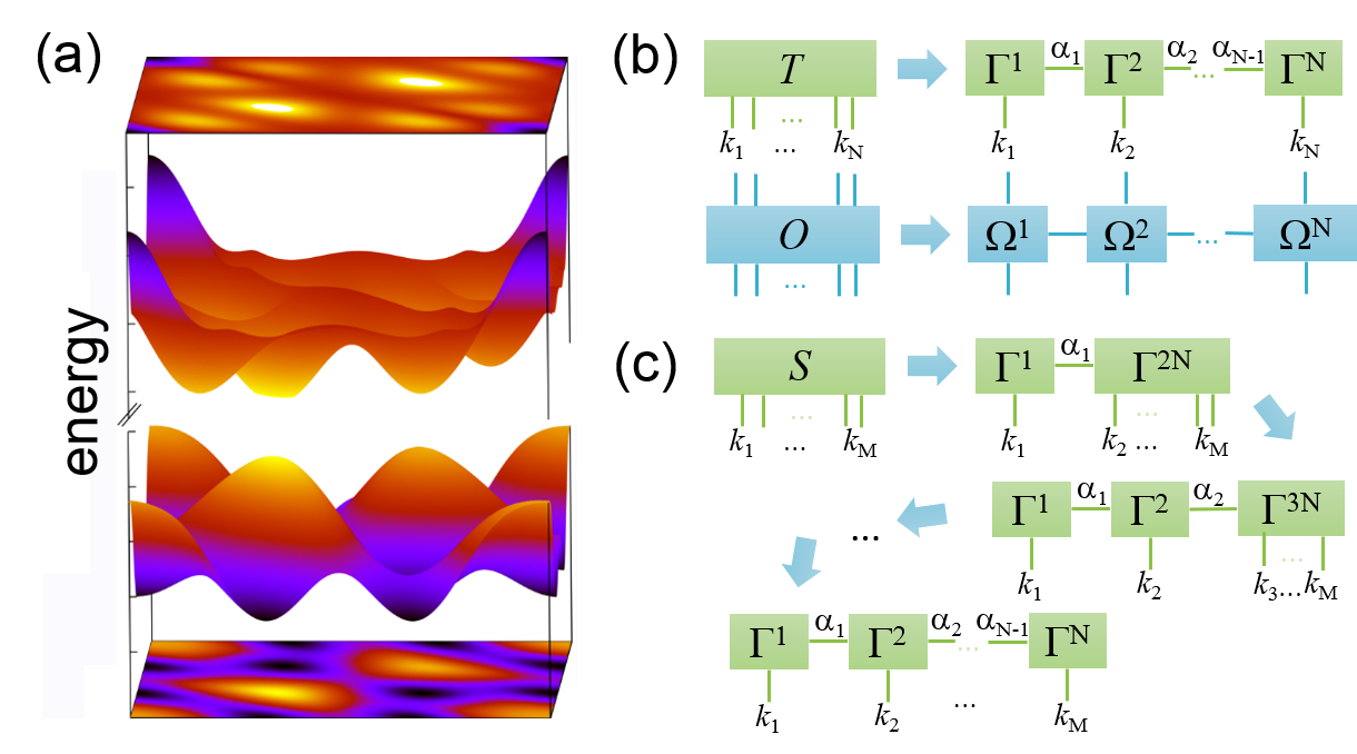
In this paper methods for calculating the bound eigenstates of electron-hole complexes are presented. Basis for the calculations is a generalization of the Wannier or Bethe Salpeter equation:
| (5) |
an eigenvalue problem for energy and the wavefunctions in reciprocal space . The wavefunction are the expansion coefficients for the many particle state . Here, is the ground state of the system with all valence bands occupied (no holes) and all conduction bands unoccupied (no electrons), so that holds. It is possible with this ansatz to calculate charged electron-hole complexes like trions or charged biexcitons Hao et al. (2017) for low doping. However higher doping requires a modified ground state and a transformation of the Hamiltonian, so that .
III Matrix product states and product operators
The wave function and also the operators acting on the wave function in Eq. (5) are stored in memory during the solution of the eigenproblem, mapping the quasi momenta onto a Monkhorst-Pack gridMonkhorst and Pack (1976) of the Brioullin zone. For high accuracy with a grid, the wave functions for a single particle as well as bright excitons are tensors with elements, resulting in a feasible eigenproblem. But electron hole complexes with higher particle numbers result in more indices such as all excitons ( elements), the trion ( elements) or the biexciton ( elements), so that the eigenproblem is not feasible anymore because of the high memory requirement. In general the overall number of tensor elements for scales as with the number of grid points and the number of particles. So that the calculation of higher electron/hole complexes such as trions and biexcitons was always carried out on grids with fewer points or a restriction to parts of the Brioullin zone Drüppel et al. (2017); Steinhoff et al. (2018b). To overcome this issue we proposed in Ref. Kuhn and Richter, 2019 to use matrix product states (MPS) Vidal (2003); Orús (2014); Schollwöck (2011); Cirac et al. (2017) (also called tensor trains in mathematics Oseledets (2009, 2010); Khoromskij (2011); Kazeev and Khoromskij (2012); Khoromskaia and Khoromskij (2015); Benner et al. (2017)) to represent the clusters. MPS were introduced in Vidal (2003), where it was shown, that every tensor can be approximated by a MPS as
| (6) |
Here, the tensors have less than elements with the maximum dimension of (link dimension). If the maximum link dimension is sufficiently small for an accurate representation of the tensor , the required memory does not scale exponentially anymore in the number of particles but linear enabling a calculation using the high rank tensors. In the following, we will use the common graphical notation for tensors, where each tensor is represented by a box and each index is depicted by a line with connected lines representing contracted indices (cf. Fig. 1). Tensors are mathematically vectors and typical vector operations such as addition, subtraction, norm, scalar multiplication are directly calculated in MPS form. Also linear operations acting on tensors can be represented as matrix product operators (MPO) (see Fig. 1b)), for which efficient applications directly to MPS exists Schollwöck (2011). Instead of using the indices for the quasimomentum , we use the binary representation of the Monkhorst-Pack grid from Eq. (2) as the indices used for the representation in MPS form. This further reduces the scaling to , so that the number of grid points only effect logarithmically the number of tensor elements. This idea comes originally from quantics tensor trains introduced in Oseledets (2009, 2010); Khoromskij (2011); Kazeev and Khoromskij (2012); Khoromskaia and Khoromskij (2015); Benner et al. (2017), here it is also beneficial, since it enables the calculation with logical circuits Kuhn and Richter (2019). Also the bit decompositions results in a hierarchical decomposition of the BZ, since for every dimension the first bit divides the BZ into an upper and lower part, and the next bits subsequently divide these parts into two halves.
Important for efficient MPOs constructed using the logical circuits is the ordering of the bits in the MPS. Bits, which are connected via logical circuits, should not be far away in the MPS in order to achieve a low link dimension in the MPO. For the tensor we will use the bit ordering (, , , …, , , …, ) for the band index, spin index, and the indices. Here is a group of bits: , cf. Fig. 3 a).
Note, that the setup used here is very different to two dimensional systems typically treated with tensor networks or MPS such as two dimensional spin lattice etc.. Our system is treated in reciprocal space. It is a periodic system with only few atoms in the elementary cell restricted to only the optical relevant valence and conduction bands. While traditionally the indices used for MPS decompositions are connected to a site (a quantum system located at a specific spatial position), here the bit representation of quantum numbers of wave functions such as the quasi moment is used for the decomposition. Therefore it is unclear, if this setup suffers from the same exponential scaling known from two dimensional spin lattice Eisert et al. (2010) and thus special care and a thorough convergence analysis is required and was done (see supplemental material of Ref.Kuhn and Richter, 2019 and Sec. IX.1 for details).
IV Converting matrix properties to MPS
A necessary step for converting Eq. (5) into MPO form is the conversion of the coefficients from Eq. (5). We start with a discussion of the bandstructure and the closely related tight binding coefficients (Note: similar quantities such as dipole moments are transformed in an analogous way). The first step is to store the whole tensor, e.g. in memory and then to recast it as with the bits as indices. The tensor is then converted using successive application of singular value decompositions (SVD) following the usual algorithm Vidal (2003) as illustrated in Fig. 1 c). However the resulting MPS has a high link dimension, so that a compression using a variational algorithm Schollwöck (2011) is carried out in the next step to reduce the link and to speed up later calculations. The same procedure is also used for the tight-binding coefficients , where only tight binding orbit index is not decomposed into bits .
The tight binding coefficients contain much more information than the bandstructure and require higher link dimensions for accurate results. Therefore we developed strategies to primarily reduce the link dimension of the compressed MPS for the tight binding coefficients. In our first attempts we tried to shift the origin of the Brioullin zone using and . The idea was that depending on the origin symmetries in the MPS bit representation are different and may lead to a lower link dimension by maintaining the same accuracy. While we saw some changes in the link dimension (may be a factor 2 or 3) before the compression, but not consistent for all quantities, the compression using the variational algorithm after the first decomposition has shown to be more effective. Instead a shift of the Brioullin zone may be used to restrict the calculation to certain parts of the Brioullin-Zone using bit masks (see discussion in Section VII).
For achieving a low link dimension, the data has to be smooth and symmetric with respect to . For example, in our first implementations the wrong bands were selected in the vicinity of points in the Brioullin zone with band crossings, while these points were energetically far away from the important K and K’ points and should not alter the results, the increased link dimensions were prohibitive. Therefore special care was taken when assigning an eigenvectors eigenvalue from the tight-binding eigenvalue problem Marzari et al. (2012) of the form:
| (7) |
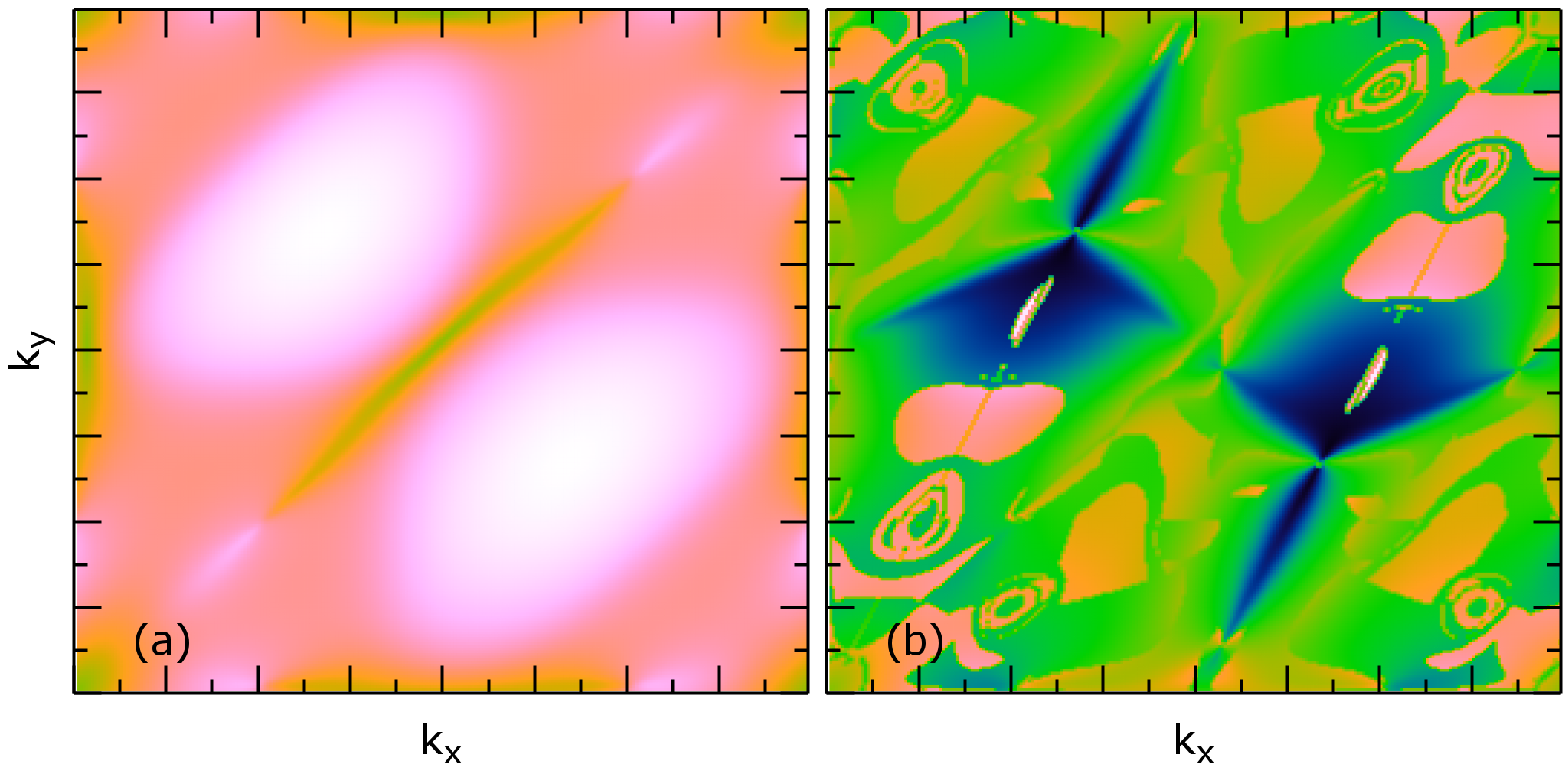
to a specific band’s energy and tight binding coefficient . One example of a successful strategy is to select an eigenvalue at a certain -point, whose tight binding coefficients changed least compared to the -points in the vicinity. Another problem is related to the phase of the tight binding coefficients, which is as usual completely arbitrary. Since the eigenvalue problem Eq. (7) is smooth in , the eigenvalue solvers show for most parts also a smooth behavior of the phase, however at certain boundaries abrupt changes of the phase occur (cf. Fig. 2 (a)). The jumps lead again to a high link dimension and need to be removed from the data before conversion to MPS. Therefore a gauge was applied that fixes the phase of one dominant orbital for a certain band and thus removes random phase jumps (cf. Fig. 2).
One might be tempted to include only the tight binding coefficients or bandstructure around the important symmetry points or in a certain energy window to reduce the information and thus the MPS link dimension. However all our attempts leaded to a significant increase in the link dimension, since the shape of the important area is encoded as well and dominates the required link dimension.
For the Coulomb potential , we use the Keldysh Coulomb potential for our model system. Here is the mean value between the surface and air. The Coulomb potential does not depend on a quasi momentum inside the Brioullin zone, but on a difference between quasi momentums. If we would just convert to a MPS using the bit representation of the Brioullin zone, for negative and/or would not be included. Instead is used as basis for the compression. This exploits the periodicity of the Brioullin-Zone and the representation of negative binary numbers in two’s complement notation Tietze et al. (2015). The further conversion to MPS is than done analog to the bandstructure etc. using the bit representation .
V MPO constructed using logical circuits
For calculating the eigenstates of Eq. (5), the equation is translated into tensor-network form. Eq. (5) is a standard eigenvalue problem:
| (8) |
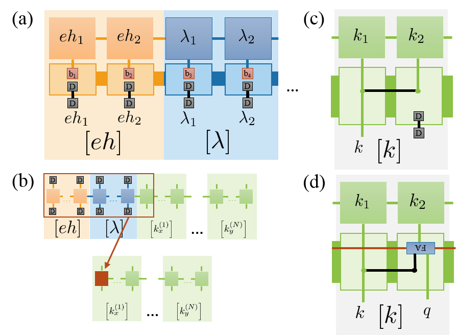
with the vector components of the wavefunction using a generalized index and a Hilbert operator matrix element . Naively viewed every summand of the rhs takes the component with the index multiplies it with the matrix element with the indices and and adds it to the resulting vector component with index . So for the tensor network, we must ensure, that from the MPS for on the rhs the correct indices (bits) are connected to the indices of final MPS (lhs), after applying the tensor network. Furthermore the matrix element connected to the initial and final indices has to be also multiplied to the final value by the tensor network. The procedure is first illustrated for the band energy term in Eq. (7): , the initial and final index are the same. Also the index for particle is connected to . Therefore we can rewrite the term as . Thus translates into a product of bitwise ’s for every k bit including band and spin.
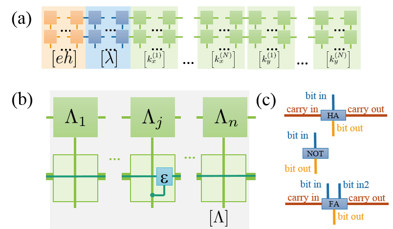
The corresponding tensor network is depicted in Fig. 3 b), for bit is written as a round dot, which connects the incoming index (connected to the lhs MPS on the top), outgoing index (resulting in the rhs) and index connected to tensor of corresponding bit index of the band structure MPS. For all other bits for particles just the ingoing and outgoing bit indices remain the same (), which is written as a straight line. The tensor network is rather simple and can be represented by a single MPS, since it is diagonal in all bit indices. Also we see already the similarity of the tensor network to logical circuits.
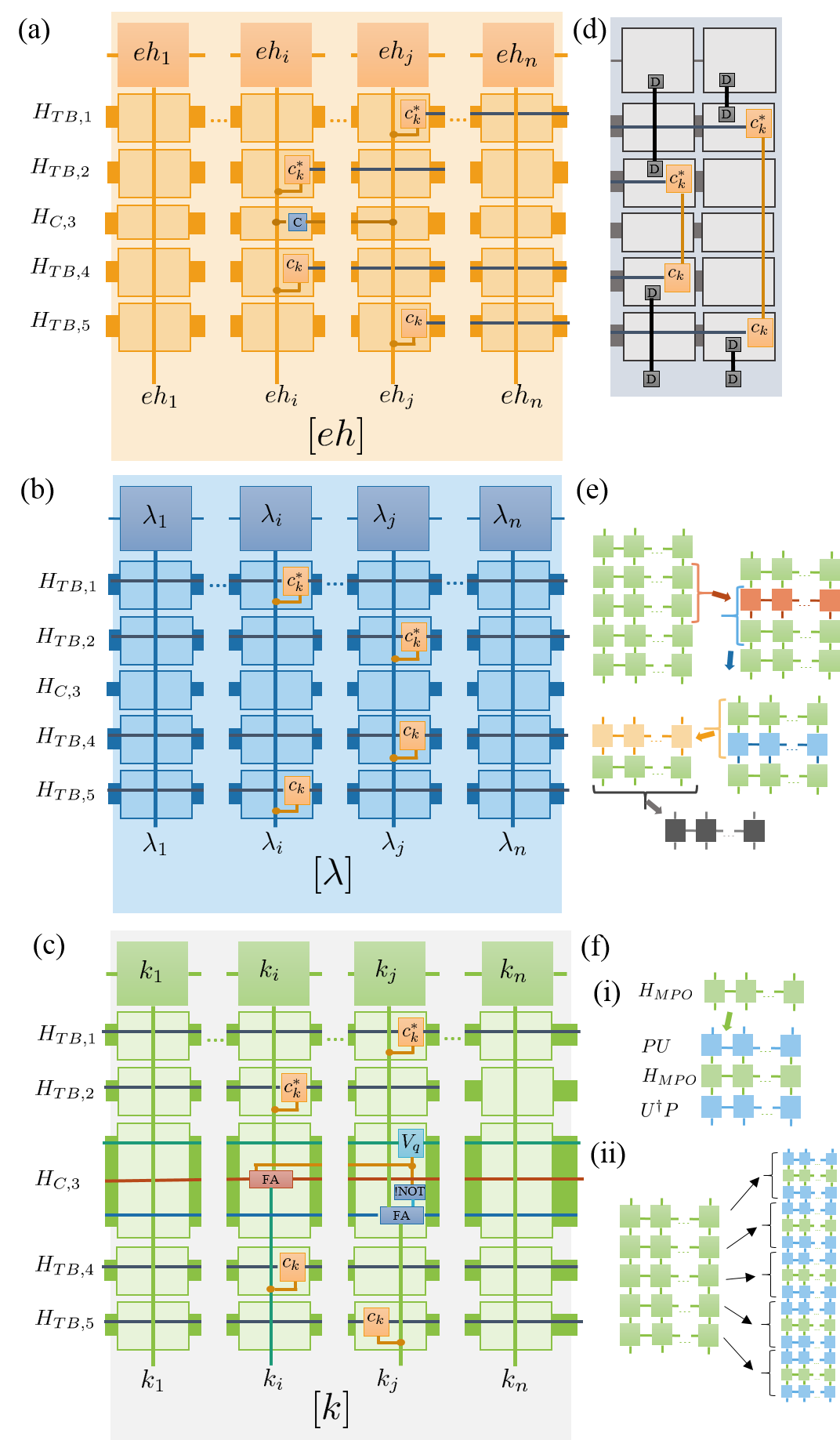
The Coulomb interaction contribution in Eq. (5) is non-diagonal in the indices. It connects the incoming indices on the rhs for particle and particle (top of Figure 4c)) to the outgoing indices and (bottom of Figure 4c)). This is implemented for every bit of the indices by two tensors, which are full adder (FA) logical circuits Tietze et al. (2015); Kuhn and Richter (2019). The carry output bit of every full adder for particle ( analog) is connected to the carry bit input of the full adder handling the next bit (cf. Fig.3c) ). The input bit of the FA handling the related bits are connected to the MPS representation of (cf. Fig.3c) ). In case of a subtraction of a NOT circuit is put on the bit input of the full adder (cf. Fig.3c) ). Note, that was exploited in the implementation. The first carry bit input of every dimension is set to for an addition and for a subtraction of , the last carry bit output is set to and by a tensor ensuring the periodic boundary conditions of the Brioullin Zone. The index handling and the multiplication of is handled in the middle MPO in Fig. 4c). The remaining parts of are () and () for the incoming indices and () and () for the outgoing indices. In this case the tight binding coefficient are diagonal in the bitindices and are each handled by one MPO, two on the top for the incoming indices (cf. Fig. 4 c)) and two on the bottom for the outgoing indices. Therefore index transformations can be applied to each of the MPOs individually, which we will use later in Sections VII,VIII,IX. The indices and are added to the end of the initial MPS and removed for the final MPS after the MPOs were applied (cf. Fig. 4d)) by merging with adjacent tensors inside the MPS for handling the sum over and . One might wonder, why we organize the tensor network into five stacked MPOs instead of a single MPO. The answer is simple, let us assume that the link dimension of the tight binding coefficients and Coulomb potentials is roughly a representation using one MPO will scale as , which is not feasible, since is typical in the order of 100. Therefore a strategy for merging the MPO will be discussed in the next section.
In the actual implementation, we generate two sets of MPOs one for the case and one for the case . This reduces the link dimension by a factor of 2 and thus the polynomial computing time.
At the end with including the band energy and Coulomb interaction a set of MPOs was generated that represents all necessary terms. In theory, the MPOs could be added before the eigenvalues are calculated. However the summed MPOs have a much higher link dimension D than the individual, so that it is for most algorithms more efficient to not sum the MPOs, but the resulting MPS (imaginary time propagation) or the environment tensors Stoudenmire and White .
V.1 Merging MPOs into a single MPO
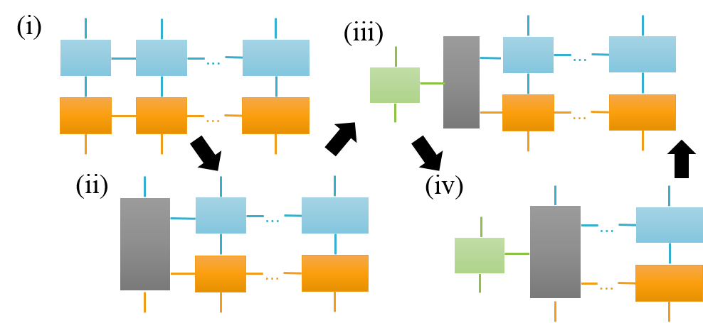
The five stacked MPOs of the Coulomb interaction have to be merged into a single MPO for algorithms like DMRG. The typical algorithm for multiplying two MPOs Schollwöck (2011); Stoudenmire and White (cf. Fig. 5) goes from left to right through the orthogonalized MPOs multiplies the tensor of the two MPOs and also does a SVD at every tensor. Afterwards the resulting MPO is orthogonalized.
Naively, the stacked MPOs can be multiplied from top to bottom to get the resulting merged MPO, but this is very inefficient and for realistic intermediate link dimensions (limited to a feasible range of a few thousands) the resulting MPO will not even describe the system qualitatively. MPS and MPO are build to efficiently represent correlated states or operations. The first two top MPOs represent tight binding coefficients and (e.g. with a maximal link dimension), but since both do not share a single index, the two MPOs are completely uncorrelated, so that a resulting MPO with acceptable precision will scale with D2 in the link dimension. On the other hand the third, middle MPO including the Coulomb potential connects all incoming and outgoing indices with each other, therefore all bits are correlated within this part of the tensor network. Therefore an efficient and accurate implementation starts with combining for example the third and the second MPO (cf. Fig. 4e)). Then the result is merged with the fourth MPO to eliminate the tight binding index and exploits its correlation with the second MPO. Subsequently the first and than fifth MPO is finally merged. In this way, we were able to get the best accuracy, since minimal links are required.
However even in this way, we could not achieve convergence within meV range, therefore the merged MPOs are only used for an initial calculation with DMRG. The final calculation with imaginary time propagation (ITP) avoids merging the stacked MPO for the Coulomb problem.
VI Methods for obtaining eigenstates

VI.1 Density matrix renormalization group (DMRG)
DMRG is a method for obtaining the system ground state, first introduced in the seminal paper of S. White White (1992). The main objective is to find a MPS , that minimizes according to Ritz’s principle. The problem is reformulated introducing the Lagrange multiplier for the ground state and finding the extreme of Schollwöck (2011)
| (9) |
for retrieving the ground state . Instead of a variation of the full MPS only the tensor inside the MPS at a specific site is varied. By placing the orthogonality center at site , we retrieve a simplified eigenvalue problem to obtain the tensor, that minimizes Eq. (9), (cf. Fig. 6 for illustration or Schollwöck (2011) for details). Important for the numerical efficiency are that the tensors of the MPS and MPO, which are not at position , are merged together into left and right environment tensor and . The link dimensions of the MPS and MPO at and determines the size of the environment tensors and and thus the numerical complexity of the problem. Therefore using stacked MPO for the Coulomb term will result in large environment tensors and thus a merging of the MPO is required.
In DMRG for obtaining the ground state MPS , is several times swept from left to right and then from right to left, while performing at every position a minimization of the tensor inside the MPS (see for example the review Schollwöck (2011) for details).
DMRG is through modifications able to calculate excited states. For example in the used itensor library Stoudenmire and White projectors for already obtained eigenstates are added into the minimization problem
| (10) |
together with a penalty energy (typical value for our simulations ). Other modified versions of DMRG for excited states were proposed in Lim and Sheng (2016); Yu et al. (2017); Khemani et al. (2016).
We use the DMRG implementation of the itensor library (version 2.1.0 patched) Stoudenmire and White , which is modified to use Hamiltonians represented as a sum of MPOs and to calculated excited states simultaneously.
VI.2 Imaginary time propagation(ITP)
While the DMRG method introduced in the last section is usually very fast and reliably allows to retrieve the ground state of most systems, we face major problems for the generalized Wannier equation. The main obstacles for the generalized Wannier equation are the tight-binding coefficients present in the Coulomb interaction (cf. tensor network in Fig. 4a)-c)), which requires a merging/multiplication of five MPOs (cf. Fig. 4e)). Even with very low precision very high link dimension in the order of thousands appear Kuhn and Richter (2019) during the multiplication. So that we could not achieve convergence for the electron-hole complexes studied here on our computing nodes. Without including the tight binding coefficients (which may be justified for an Ansatz including only certain parts of the Brioullin zone), a calculation of larger electron hole complexes states is feasible using DMRG with calculation times around hours. Including the tight-binding coefficients the merging/multiplication of the involved MPO’s consumes the majority of the time (cf. Fig. 4e)).
Of course, achieving convergence is much easier, if MPO merging is avoided. So that instead of representing a single part of the Hamiltonian as one MPO, we keep the five unmerged MPO . For DMRG, using the unmerged MPOs is not possible. In principle, the minimization of in DMRG could be written with unmerged MPOs for the contribution . However the environment tensors ( and ) inside the DMRG algorithm will scale roughly with . Typical values are in the range from 30-200 leading to in the range from to , which is not feasible. This shows clear future demand for a modification of the DMRG algorithm. On the other hand, we can solve the time dependent Schrödinger equation:
| (11) |
For calculating the time propagation, it is required to apply the Hamiltonian as MPO to the current MPS state . For the unmerged MPO , a successive application , ,…, , is possible and avoids the merging of MPO. The MPS truncation (the vector) can be achieved with much higher accuracy than a MPO (the matrix) truncation, since we hold only the information, how a single vector (MPS) is transformed by the Hamiltonian and not the information how any vector is transformed by the merged Hamiltonian (MPO). In practice, we use a variational approach Schollwöck (2011); Stoudenmire and White for the application of the MPO to the MPS states, since the exact application is too slow.
A numerical solution of the time dependent Schrödinger equation does not lead to the eigenvalues and eigenstates of the system. However, if the time is replaced by , we arrive at an equation for imaginary time propagation (ITP) Schollwöck (2011):
| (12) |
with the formal solution . Expanding into the eigenstates of with eigenenergy yields with the formal dependent solution
| (13) |
If holds for the ground state energy and we define we see immediately from
| (14) |
that , i.e. for long times propagates towards the ground state. Or more precisely the wavefunction propagates towards the eigenstate with the lowest energy included in the expansion with . This is exploited later for the calculation of excited states. Usually propagation starts with a random MPS for , which should include contributions from the lowest energy eigenstate. Numerical errors or errors due to the MPS approximation are beneficial for the algorithm, since these may expand the number of eigenstates included in .
For the implementation we take Eq. (12) and replace with using as parameter to shift the energy axis and use a first order Euler approximation:
| (15) |
for calculating the ITP using a variational algorithm algorithm Schollwöck (2011); Stoudenmire and White (fitMPOapply from itensor), than is immediately normalized after every time step. Before normalization allows to calculate the average energy. Furthermore and recognizing that allows to decide if the propagation is close to a single eigenstate, since for a single eigenstate the propagation reaches , if is calculated without approximations.
VI.3 Combined approaches
In practice, it is useful to start the calculation of an eigenstate with a DMRG calculation. Even if the result is not converged, the overall structure of the eigenstates is in general close enough to the converged result, that propagation until convergence in a subsequent ITP is drastically faster using the DMRG result as starting point for the propagation. This works always for the ground state inside the subspace of the calculation, since ITP will always lead to the ground state. However some times the variational application of the MPO in the ITP is stuck inside a subspace, in these cases a subsequent ITP starting from the excited states from DMRG will also work for retrieving excited states. We will discuss this in detail for the different applications (see section IX.1).
VII Exciton states
VII.1 Coordinate transformations
In most treatments only the optical active exciton states are of interest, this is routinely done Haug and Koch (2009); Berghäuser and Malic (2014); Mostaani et al. (2017); Schmidt et al. (2016); Richter (2017); Specht et al. (2019); Qiu et al. (2013b) without tensor networks. For the tensor network method the optical active states are a benchmark and to illustrate and test concepts, which are applied for larger electron hole complexes (trion and biexcitons). Exciton states in general benefit from the tensor networks, since higher grid sizes are easily possible as well as test of common approximation and physical mechanism such as a restriction to a part of the Brioullin zone, hybridization between K and K’ excitons and effective mass description.
Starting point for the exciton wavefunction is the two particle wavefunction together with the generalized Bethe-Salpeter Eq. (5). However the calculation of the ground state for will not yield an exciton but the wave function of two holes, since so far all possible combinations of bands, spins are included in the MPO implementation of Eq. (5). So for retrieving an exciton is calculated, setting for example the first particle to conduction band and spin and the second to valence band and spin . Furthermore often a calculation of optical active excitons is desired with only diagonal contributions to the exciton wave function . The restriction to a certain combination of bands and spins as well as taking only diagonal optical active states are both projections into a subspace of the Hilbert space. We will use in the following a combination of a projection and a coordination transformation . For applications together with the tensor networks, are MPOs and are presented here for the different index transformations (including the other quasi particles).
Every MPO describing a part of the term in the Eq. (5) is replaced with in the calculation (see Fig. 4f)(i)). has to be chosen, so that every is diagonal in the subspace, i.e. , holds. This requirement also applies for every of the stacked MPOs for the Coulomb term (cf. Fig. 4f)(ii)), since is applied to each MPO individually. It is also imperative to remove sites from the MPSs and MPOs, so that only the subspace of is indexed by them. Otherwise for example DMRG will calculate a state inside , for which the eigenvalue will be , since .
We illustrate the construction of a projector for the bits for band and spin, i.e. for , in Fig. 7a). The projector terminates the bits with the selected band or spin and the site dimension is set to using a tensor . The projector is than applied to the original MPO as , see Fig. 4f). In a second step, the tensor of the MPO with fixed site bits are terminated by a tensor and merged with the adjacent tensors inside the MPO (see Fig. 7b)).
A projector restricting the calculation to optical active excitons with diagonal index, e.g. , is constructed by connecting the two adjacent site bits to a delta tensor as depicted in Fig. 7c). One of the bit is obsolete after connecting the delta tensor and the connected tensor is removed after applying the projector to the Hamiltonian by merging with an adjacent tensor (analog to the band and spin indices cf. Fig. 7 a) and b)).
| State | DMRG | ITP | Restriction | Fig.9 |
| ground state | 1.762 | 1.767 | none | c) |
| (momentum dark) | 1.764 | 1.769 | big box at K | |
| 1.785 | 1.790 | small box at K | ||
| A 1s (bright) | 1.758 | 1.769 | a) | |
| 1.766 | 1.769 | box | ||
| (spin dark) | 1.755 | 1.763 | b) | |
| B 1s (bright) | 1.897 | 1.906 | d) | |
| 1.904 | 1.911 | big box at K’ | ||
| 1.927 | 1.934 | small box at K’ | ||
| (spin dark) | 1.900 | 1.912 | ||
| A 2p (bright) | 1.971 | |||
| (spin dark) | 1.969 | |||
| B 2p (bright) | 1.802 | |||
| (spin dark) | 1.802 | |||
| K-Q | 1.950 | 1.936 | (i) fixed value | e) |
| 1.946 | 1.938 | (ii)fix upper bits of | ||
| and |
VII.2 Numerical results
We start with a discussion of numerical results for the diagonal bright exciton . For example a DMRG calculation, chosen so that it is a fast and good starting point for ITP but not necessarily with accurate energies, yields for the lowest three bright and (spin forbidden dark) A 1s exciton (Fig. 9a)), B 2p exciton, B 1s exciton (Fig. 9d)) etc. the energies as given in Table 1 (with restriction ). As written earlier, we could not achieve convergence for the DMRG case due to the tight binding coefficients. Hence all DMRG calculations in this paper provide initial states for a fast ITP calculation and are calculated with reduced accuracy (cf. in Table 1 the unusual energy ordering of the states).
A calculation using ITP, which numerical converged, yields very different results for the bright and dark A 1s exciton (Fig. 9a)), B 1s exciton (Fig. 9d)), A 2p exciton and (cf. Table 1). Taking the DMRG result as start point for the ITP yields the same energy of for the A 1s exciton. For the excited states the procedure does not work, since in this case the ITP always retrieves the ground state, the A 1s exciton.
In order to get reliable results, a careful convergence analysis is required for the MPS of the band structure, Coulomb potential etc. as well as the parameters of DMRG or ITP for excitons, but also for trions and biexcitons, see supplemental material of Ref. Kuhn and Richter, 2019 and also Sec. IX.1 for the analysis and parameters used here. Indeed the large grid size of is necessary for a high accuracy of the exciton binding energy. The convergence analysis also ensures, that we do not encounter problems from a potential unfavorable entropy scaling in two dimensionsEisert et al. (2010).
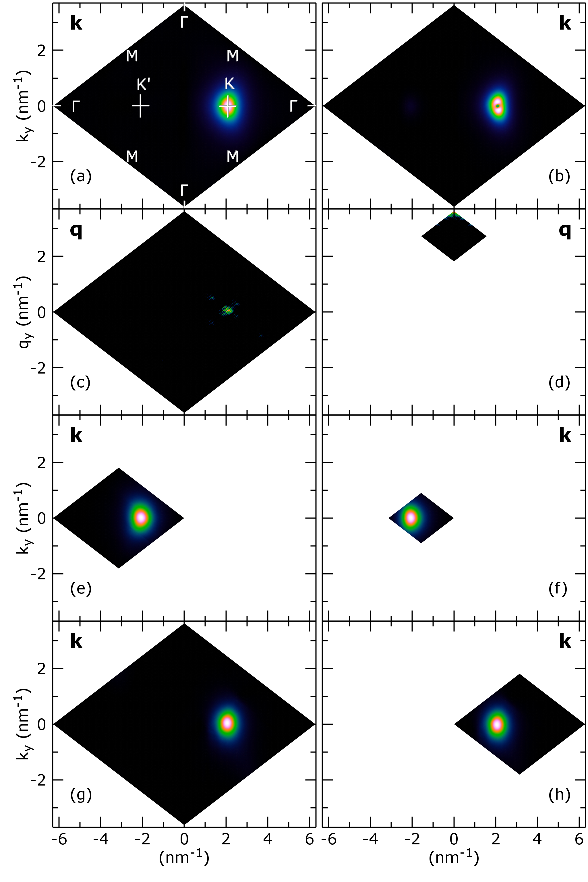
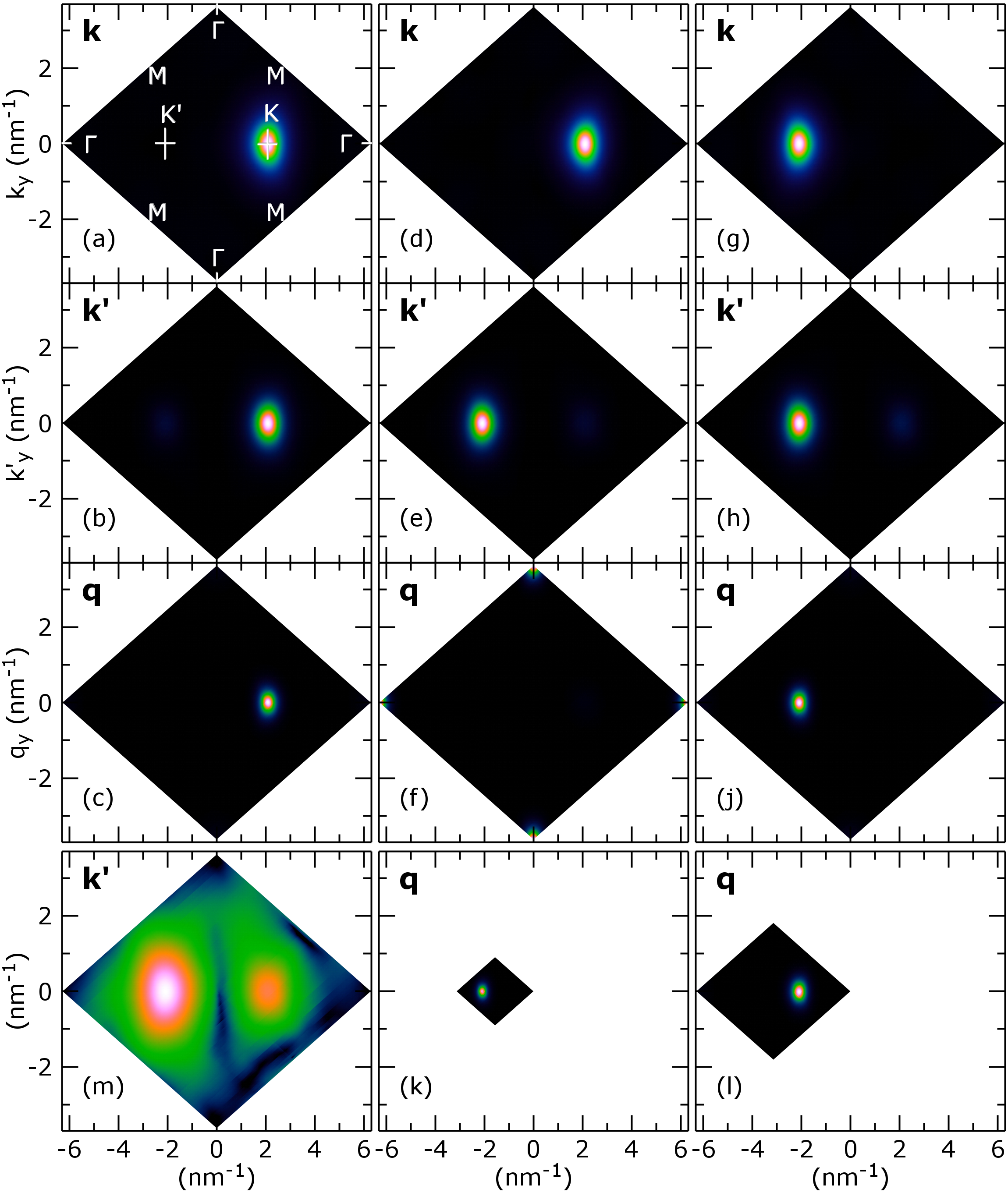
Calculating the bright -diagonal exciton states is not special and routinely carried out without tensor networks Haug and Koch (2009); Berghäuser and Malic (2014); Mostaani et al. (2017); Schmidt et al. (2016); Richter (2017); Specht et al. (2019); Qiu et al. (2013b). However tensor networks enable also to calculate without setting , so that deviations from a center of mass motion and momentum forbidden excitons are addressed. The index transformation is beneficial, since Coulomb interaction will leave invariant and thus should be a delta peak at a single . Furthermore similar index transformations are required for trions and biexcitons, so that concepts are tested here at the known exciton level. The index transformation of and to and is handled by a fulladder circuit similar to the Coulomb interaction (Fig. 7d)). The DMRG calculation as input for ITP reveals an ground state exciton energy of 1.762 eV and a subsequent ITP yields 1.767 eV. The energies are different to the previous calculation using diagonal momenta (, cf. Table 1). For the seed DMRG deviations are expected, but not for ITP. However, an inspection of the exciton wave function shows that here the ground state is an optically momentum forbidden K-K’ exciton (see Fig. 8c)) with electron and holes being at different symmetry points. Therefore the desired bright 1s A exciton is an excited state in this case an ideal testing case for strategies needed later for the bright biexciton.
The excited states retrieved by DMRG are completely unordered but the low energy states are also momentum forbidden 1s K-K’ excitons and are describing the center of mass continuum of the ground state. In this way the grid used for the Brillouin Zone is a curse (it also haunts the biexciton problem), since a huge number of dark continuum states for the ground state is retrieved more than is actually feasible to also access other excited states. Therefore strategies for calculating selectively the excited states are required.
One way is to set to a fixed value (the optical allowed diagonal case is the special case ), which is exact, since the Coulomb interaction leaves invariant. In this case, the bits are set to the fixed value and removed afterwards, analog to the procedure for the band and spin indices. Often the exciton state with the smallest energy with electron and holes at certain symmetry points is desired or the momentum dark state instead of the bright state or vice versa. In this case, we set the upper bits of to a fixed value, restricting to a box around bit boundaries (cf. Fig. 8d)).
On the other hand the same can be applied to , e.g. to focus only on certain symmetry points. If the boxes do not fit well to the desired symmetry points, the Brillouin zone can be shifted by and . Restricting is actually an approximation, since superpositions between different symmetry points due to Coulomb interaction are prohibited. However a restriction to certain symmetry points is a common approximation Berghäuser and Malic (2014); Steinhoff et al. (2018b), which we test here: The bright A exciton is calculated by restricting the momentum to a box including , therefore fixing the upper two bits of every dimension to 0 (cf. Fig. 8d)). An energy of 1.766 eV is retrieved in the seed DMRG and of 1.769 eV in the subsequent ITP, showing no deviation from the calculation of the bright exciton before in ITP (cf. Table 1).
For retrieving higher excited states such as the bright B exciton we fix the upper bits of to restrict it to a box around the symmetry point such as K or K’. For the momentum forbidden ground state exciton (Fig. 9c)), we retrieve 1.764 eV (1.785 eV) in DMRG and 1.769 eV (1.790 eV) in ITP for a big (small) box (cf. Fig. 8c)). For the 1s B exciton the energy is 1.904 eV (1.927 eV) in DMRG and 1.911 eV (1.934 eV) in ITP for a big (small) box (cf. Fig. 8e)f)). The approach does not include couplings/hybridization between the K-K’ point (cf. Berghäuser et al. (2018)) and thus changes the energies slightly by a few , showing that for MoS2 the hybridization and thus the Coulomb hybridization (cf. ”Dexter” coupling in Berghäuser et al. (2018)) leads to a shift of several meV and that the full Brioullin zone should be included in the calculation. Also it is clear, that the box has to be big enough to include the full wave function (cf. the error of over 10 meV for a small box).
Furthermore K-Q excitons are in the focus of current investigations Selig et al. (2018); Deilmann and Thygesen (2019). Two strategies are possible to access these: (i) is set to a fixed value (the distance between K-Q) and (ii) the upper bits of and are fixed, so that the state is found inside these boxes. The results for both cases are given in Table 1. We notice a small shift of in case of (ii) compared to the distance between K and Q, which was used in case (i) for the fixed . The difference of a few eV (cf. Table 1) may be solely attributed to the box used to confine . Note, that in case of fixed , we can easily access excited states like 2s, 2p etc, since it is similar to the diagonal bright case.
VIII Trion states
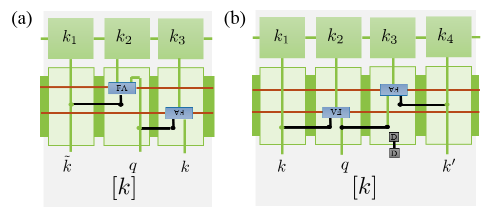
The trion is the next bigger bound electron hole complex after the exciton. A trion is a charged exciton with an additional electron or hole included in the complex. In the low density limit, the optical created trions does not start from the neutral ground state , but from a state with already an hole or an electron with momentum present in the system, corresponding to the wavefunctions or . The momentum added by optical excitation of the additional electron hole pair is negligible, thus that the overall momentum of a bright trion is the momentum of the initial carrier. In general the wavefunction of a trion is for T-: and T+: , for which the generalized Bethe Salpeter Eq. (5) holds. If only bright trion complexes are of interest, the coordinate transformation or is beneficial with momentum of the initial carrier or the whole trion. Since the Coulomb interaction does not change in these coordinates, can be set to a fixed value. The coordinate transformation UP is implemented as MPO including two fulladder circuits for every k bit (see Fig. 10a)). For the calculation the k bits can be fixed analog to fixing q bits in the exciton case. A separate calculation of the trion eigenstates is required for every . The calculation is very efficient, but we can not calculate trion eigenstates for the whole 1024x1024 grid. If trion binding energies are of interest, the carrier momentum is placed at band minima at typical symmetry points. If a calculation of the line shape is of interest as in Ref. Esser et al., 2000, a coarse grid around the symmetry points can be used to retrieve an approximation of the overall shape.
As in the exciton case, the trion states are first calculated with a low accuracy DMRG calculation and a subsequent ITP achieves convergence. While in the exciton case the link dimension of the MPS during ITP was effectively unrestricted, we had to restrict the link dimension in the trion and biexciton case. For a fast calculation the ITP typically starts with a restricted link dimension of 200, after being close to the final state the ITP continues briefly with a link dimension of 500. (See biexciton section IX.1 for a detailed analysis of the strategy.)
| Type | Configuration | Restriction | Fig. 11 | |||
| T- A | 1.742 | 27 | K’ | none | a) | |
| 1.746 | 23 | K | d) | |||
| T- B | 1.885 | 21 | K | Sec.IX.1 | ||
| T- A | 1.756 | 13 | K’ | box K’ | b) | |
| 1.748 | 21 | K’ | big box K’ | |||
| 1.7425 | 27 | K | none | c) | ||
| T+ A | 1.740 | 29 | K’ | none | e) | |
| 1.736 | 33 | K ’ | none | f) | ||
| 1.739 | 29.4 | K | h) | |||
| 1.739 | 30 | K | box | g) |
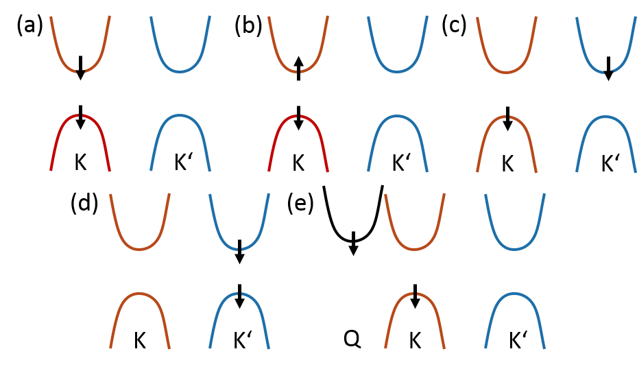
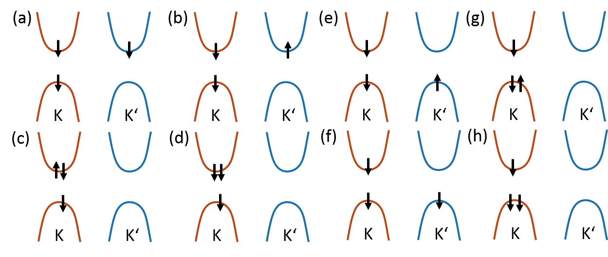
We start with example states for the negatively charged trion T- with at the K’ point. The resulting trion has an electron hole pair at the K point and an excess electron at K’ as depicted in Fig. 11 a) with a transition energy of 1.742 eV and a trion binding energy of 27 meV. The transition energy of the trion is the difference between trion energy and energy of initial free carrier with momentum . The binding energy is the difference between the transition energy and the exciton energy. For getting the configuration in Fig. 11b), we use an initial electron at K’ with spin up (flipped compared to a)) and restrict to a box around K’ (cf. section VII.2) for the wavefunction . A small box (upper two bits fixed) yields a transition energy of 1.756 eV in ITP and a binding energy of 13 meV. A bigger box (upper bit fixed) results in a transition energy of 1.748 eV in ITP and a binding energy of 21 meV. So in contrast to the exciton case, where is delta-like, the introduction of a too small box introduces a substantial error for the broad distribution for the trion. A small error can remain for the bigger box (cf. Sec. IX).
For an initial carrier with at the K point, we yield for the spin configuration a trion T- with all carriers at the K point as depicted in Fig. 11 c), ITP results in a transition energy of 1.7425 eV and a binding energy of 27 meV. So only a slightly higher transition energy as the configuration with equal spin and the K’ point electron. On the other hand also a T- configuration with equal spin with all electron and holes at K point (initial electron also at K point) exist as shown in Fig. 11d) with higher transition energy 1.746 eV and lower 23 meV binding energy. Note, often this state is excluded using Pauli exclusion principle as argument, but this holds only for level systems like quantum dots, the existence of the triplet states is well known for quantum wells Peeters et al. (2001); Palacios et al. (1996) and the reduction of the binding energy is a result of the interplay of Pauli exclusion principle and Hund’s rule. From calculating we also retrieved an excited containing a B exciton using the technique described in section IX.1 and an initial maximum link dimension 100 for ITP (in principle Fig. 11 a) with K and K’ exchanged) with transition energy 1.885 eV and binding energy 21 meV.
We continue with example states for the positive charged trion T+ for the spin configuration with at the K’ point, we yield the trion as depicted in Fig. 11 e) with at the K’ point. ITP gives a transition energy of 1.740 eV and a binding energy of 29 meV. For the equal spin configuration also with at the K’ point (cf. Fig. 11 f)), ITP results in a transition energy of 1.736 eV and a binding energy of 33 meV. Here the different spin of the excess carrier slightly alters the Coulomb contribution. For T+ also trions with at the K point exist, however for retrieving the state using the configuration , had to be restricted around K (cf. Fig. 11 g)) and yield after ITP a transition energy of 1.739 eV and a binding energy of 30 meV compared to the bright exciton. So compared to the case with at the K’-point, the T+ with equal spins and with at the K point does not require a restriction of and yield a transition energy of 1.739 eV and a binding energy of 29.4 meV, so only slightly changed compared to the different spin case (cf. Fig. 11 h)).
Furthermore the differences between having all carriers at the same or at different or are not so pronounced for the positive as for the negative charged case. This might be a consequence of lower effective masses.
Overall the order of magnitude of the calculated trion binding energies agree with current literatureDrüppel et al. (2017); Szyniszewski et al. (2017); Kylänpää and Komsa (2015). For the trions one drawback of the method was, that we had to guess the spin configuration, the position of the initial carrier and also to use constraints for some states. So we had to select beforehand the configuration of interest and did not obtain a complete set of states, therefore only selected examples are given. A systematic study of the states is subject to future work.
| Type | Configuration | Method | Fig. 12 | ||
|---|---|---|---|---|---|
| A-A (dark) | 3.506 | 27 | Sec. IX.1 | b) | |
| A-A | 3.519 | 19-20 | Sec. IX.1 | a) | |
| (bright) | 3.536 | 1-2 | small | ||
| 3.523 | 15 | big | |||
| box at K’ | |||||
| 3.518 | 20 | Sec. IX.1 | |||
| B-B | 3.791 | 21 | Sec. IX.1 | d) | |
| A-B | 3.655 | 20 | Sec. IX.1 | c) |
IX Biexciton states
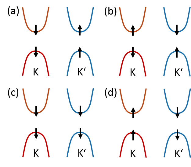
Biexcitons are electron-holes complexes with one additional particle more than a trion. Biexcitons consists of two electrons and holes and can be viewed as bound states made from two excitons. The biexciton wavefunction is calculated using the generalized Bethe-Salpeter Eq. (5). The optical created biexcitons as in the exciton case have overall vanishing momentum, therefore a transformation such as with overall vanishing momentum excludes some dark biexcitons (see Fig. 10b) for the tensor network implementation). Unfortunately it does not exclude every dark biexciton, since we include the full Brioullin zone (a drawback of the full calculation). For example the typical ground state bright exciton in MoS2 consists of two spin allowed excitons one at K and one at K’ point (cf. Fig. 12a) or Fig. 13(d-f)), however a biexciton made from two spin forbidden excitons one at K and one at K’ point (cf. Fig. 12b) or Fig. 13(a-c) ) is included in the same biexciton wavefunction (of course due to small hybridizations between K and K’ the dipole moment does not vanish completely but is much smaller). Unfortunately the dark biexciton, which is uninteresting for optical applications, has a smaller energy than the bright biexciton, so that the retrieval of the bright biexciton for example from ITP (theoretical always retrieving the ground state) is tricky. One way is to use as starting point for the ITP bright biexciton state calculated with DMRG even with low numerical convergence. In principle, the ITP should retrieve the biexciton ground state, but due to limits in the link dimension and variational approach for applying the MPOs often it does not change the overall symmetry of the eigenstate and is stuck inside a local subspace. In order to retrieve with DMRG the biexciton state of interest, we often ran the DMRG several times, since for the biexciton case DMRG was often trapped in local minima of the problem, where the symmetry and ordering of the retrieved states depended on the random initial vector. Furthermore it was also beneficial to use DMRG with parameters resulting in low convergence, e.g. low link dimension or numerical accuracy, since we obtained often biexciton states with very different symmetries (e.g. s, p and even d like contributions) in this case. So the ground state, the dark biexciton is retrieved from a DMRG of and subsequent ITP (cf. Fig. 13 (a-c)) yielding an energy of 3.506 eV and thus a binding energy of 27 meV. Another DMRG run allowed to retrieve the lowest bright biexciton and a subsequent ITP (using the strategy from section IX.1) with energy 3.519 eV and a binding energy of 19-20 meV (cf. Fig. 13(d-f)).
Another way to retrieve the bright biexciton is to limit to a box (similar to the exciton and trion case). This requires the spin configuration together with restricted around K’ fixing the upper two bits (Fig. 13 k)). The calculation yields a bright exciton state with energy 3.536 eV and binding energy around 1-2 meV, which differs considerably from the previous result! A calculation with a bigger box for fixing only one bit results in an energy of 3.523 eV and binding energy 15 meV (cf. Fig. 13 l)), but required a higher accuracy for applying UP and link dimension in the seed DMRG. The binding energy is still 5 meV smaller than the previous result, but the major deviation came from a too small box for effectively preventing the biexciton binding process (cf. Fig. 13k) l) ). Furthermore the deviation is roughly twice as large as the error introduced by restricting an exciton to a big box around the K point. Therefore the deviation is caused by a suppression of the K-K’ hybridization. This is confirmed by hybridization present in the bright biexciton calculated also for this spin configuration using the method from Sec. IX.1 (cf. Fig. 13 (h) ) for the hybridization), which agrees to the previously calculated energy 3.518 eV and binding energy 20 meV and is depicted in Fig. 13 (g-j).
Beside the bright 1s A-A biexciton also allows to retrieve the bright 1s B-B biexciton (cf. Fig. 12d)) with 3.791 eV and 21 meV binding energy.
Another interesting state is the bright 1s A-B biexciton, which can be retrieved from . Two states are retrieved one with , , around K and one around K’, both with the energy 3.655 eV and 20 meV binding energy within numerical accuracy. These are actually not two different eigenstates, but the same eigenstate, since the ansatz using only the expansion coefficients does not guarantee the correct permutation symmetry. Therefore a linear combination of the two degenerate results yields biexciton state with the proper symmetrization. This does not effect the eigenenergies, but for a calculation of matrix elements, proper symmetrization is required using the expansion coefficients from the calculation presented here.
Furthermore for all biexciton states a small hybridization for the hole between K and K’ is visible for (cf. Fig. 13 (b), (e), (h) and (m)), if is not restricted. We yield in all cases almost the same energy, since our model system is lacking short range exchange interaction Steinhoff et al. (2018b).
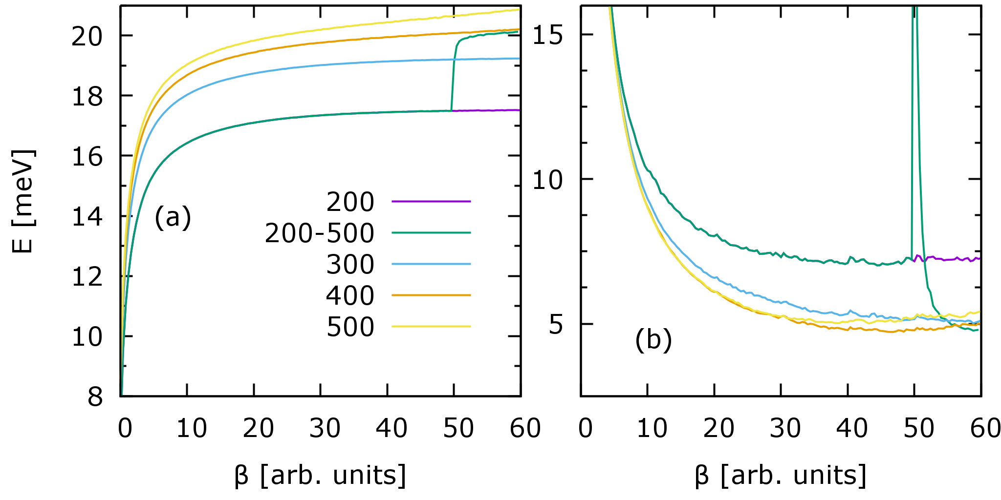
IX.1 Convergent and fast calculations
The link dimension of the MPS appearing during ITP for trion and biexcitons for a truncation precision of exceeds the feasible range. Therefore the link dimension is truncated, which due to the polynomial scaling of the computation time and memory leads to a significant speed up. The energy and energy variation is plotted over propagation time in Fig. 14 a) and b) for the bright biexciton state (note the dark biexciton state is the ground state). The energy in Fig. 14 a) converges at least for the low link dimension (up to 300) for increasing, also for clearly converges for increasing link dimension. But for the for 300 and 400 link dimension does not seem to converge for and also increasing link dimension does not seem to lead to convergence. Decreasing in Fig. 14 is an indicator for convergence and for up to link dimension 400 it goes to a fixed value (for biexcitons typically 5 meV, for excitons and trions typically 0.5-2 meV ). But is actually slightly increasing for link dimension 400 and 500 a clear sign that the propagation is leaving the initial bright biexciton state and propagating towards the (dark) biexciton ground state. For lower link dimensions the subspace of the propagation is so small, that the MPS sticks to the type of the initially prepared state. This explains the convergence problems visible in Fig. 14 after and of course does not occur, if we calculate the ground state within the projector .
In order to keep the initial state, which is not the ground state, it is better to raise the link dimension relatively late during ITP for a relative short remaining propagation time (see Fig. 14 link 200-500). In this way the calculation benefits from the fast calculation with small link dimension and the small propagation subspace in the beginning and the good energy convergence for the high link dimension at the very end. Therefore this strategy was used for most trion and biexciton calculations in this paper.
Please note that is not necessarily an absolute measure of the error of the eigenstate energy, but about the quality of the wave function (admixture from other eigenstates) and that it is also affected by a truncated link dimension.
X Conclusion
Detailed strategies, algorithm and background information for an efficient calculation of bound electron hole complexes in two dimensional material such as MoS2 using tensor network methods were given in this paper. Furthermore example calculations for exciton, trions, biexcitons showed how to selectively retrieve specific bound states. We believe, that the tensor methods with logical circuits will enable the calculating bound electron hole complexes on the full Brioullin zone with high resolution grid discretization for many future applications.
Acknowledgements.
We gratefully acknowledge support from the Deutsche Forschungsgemeinschaft (DFG) through SFB 787 B1 (Project No. 43659573).References
- Lindberg and Koch (1988) M. Lindberg and S. W. Koch, Physical Review B 38, 3342 (1988).
- Butscher et al. (2005) S. Butscher, J. Förstner, I. Waldmüller, and A. Knorr, Physical Review B 72, 045314 (2005).
- Malić et al. (2008) E. Malić, M. Hirtschulz, F. Milde, M. Richter, J. Maultzsch, S. Reich, and A. Knorr, physica status solidi (b) 245, 2155 (2008).
- Reiter et al. (2007) D. Reiter, M. Glanemann, V. Axt, and T. Kuhn, Physical Review B 75, 205327 (2007).
- Schmidt et al. (2016) R. Schmidt, G. Berghäuser, R. Schneider, M. Selig, P. Tonndorf, E. Malic, A. Knorr, S. Michaelis de Vasconcellos, and R. Bratschitsch, Nano Letters 16, 2945 (2016), pMID: 27086935, https://doi.org/10.1021/acs.nanolett.5b04733 .
- Chatterjee et al. (2004) S. Chatterjee, C. Ell, S. Mosor, G. Khitrova, H. M. Gibbs, W. Hoyer, M. Kira, S. W. Koch, J. P. Prineas, and H. Stolz, Phys. Rev. Lett. 92, 067402 (2004).
- Winzer et al. (2010) T. Winzer, A. Knorr, and E. Malic, Nano letters 10, 4839 (2010).
- Meckbach et al. (2018) L. Meckbach, T. Stroucken, and S. W. Koch, Phys. Rev. B 97, 035425 (2018).
- Qiu et al. (2013a) D. Y. Qiu, H. Felipe, and S. G. Louie, Phys. Rev. Lett. 111, 216805 (2013a).
- Berghäuser and Malic (2014) G. Berghäuser and E. Malic, Phys. Rev. B 89, 125309 (2014).
- Qiu et al. (2015) D. Y. Qiu, T. Cao, and S. G. Louie, Physical review letters 115, 176801 (2015).
- Haug and Koch (2009) H. Haug and S. W. Koch, Quantum Theory of the Optical and Electronic Properties of Semiconductors: Fivth Edition (World Scientific Publishing Company, 2009).
- Hüser et al. (2013) F. Hüser, T. Olsen, and K. S. Thygesen, Physical Review B 88, 245309 (2013).
- Ridolfi et al. (2018) E. Ridolfi, C. H. Lewenkopf, and V. M. Pereira, Phys. Rev. B 97, 205409 (2018).
- Deilmann and Thygesen (2019) T. Deilmann and K. S. Thygesen, 2D Materials 6, 035003 (2019).
- Steinhoff et al. (2018a) A. Steinhoff, T. Wehling, and M. Rösner, Physical Review B 98, 045304 (2018a).
- Stébé et al. (1997) B. Stébé, G. Munschy, L. Stauffer, F. Dujardin, and J. Murat, Physical Review B 56, 12454 (1997).
- Mayrock et al. (1999) O. Mayrock, H.-J. Wünsche, F. Henneberger, C. Riva, V. Schweigert, and F. Peeters, Physical Review B 60, 5582 (1999).
- Esser et al. (2000) A. Esser, E. Runge, R. Zimmermann, and W. Langbein, physica status solidi (a) 178, 489 (2000).
- Esser et al. (2001) A. Esser, R. Zimmermann, and E. Runge, physica status solidi (b) 227, 317 (2001).
- Mostaani et al. (2017) E. Mostaani, M. Szyniszewski, C. Price, R. Maezono, M. Danovich, R. Hunt, N. Drummond, and V. Fal’Ko, Physical Review B 96, 075431 (2017).
- Singh et al. (2016) A. Singh, G. Moody, K. Tran, M. E. Scott, V. Overbeck, G. Berghäuser, J. Schaibley, E. J. Seifert, D. Pleskot, N. M. Gabor, J. Yan, D. G. Mandrus, M. Richter, E. Malic, X. Xu, and X. Li, Phys. Rev. B 93, 041401 (2016).
- Florian et al. (2018) M. Florian, M. Hartmann, A. Steinhoff, J. Klein, A. W. Holleitner, J. J. Finley, T. O. Wehling, M. Kaniber, and C. Gies, Nano Letters 18, 2725 (2018), pMID: 29558797, https://doi.org/10.1021/acs.nanolett.8b00840 .
- Zhang et al. (2015) D. K. Zhang, D. W. Kidd, and K. Varga, Nano Letters 15, 7002 (2015), pMID: 26422057, https://doi.org/10.1021/acs.nanolett.5b03009 .
- Kidd et al. (2016) D. W. Kidd, D. K. Zhang, and K. Varga, Phys. Rev. B 93, 125423 (2016).
- Drüppel et al. (2017) M. Drüppel, T. Deilmann, P. Krüger, and M. Rohlfing, Nature Communications 8, 2117 (2017).
- Steinhoff et al. (2018b) A. Steinhoff, M. Florian, A. Singh, K. Tran, M. Kolarczik, S. Helmrich, A. W. Achtstein, U. Woggon, N. Owschimikow, F. Jahnke, and X. Li, Nature Physics 14, 1199 (2018b).
- Katsch et al. (2019) F. Katsch, M. Selig, and A. Knorr, 2D Materials 7, 015021 (2019).
- Kuhn and Richter (2019) S. C. Kuhn and M. Richter, Phys. Rev. B 99, 241301 (2019).
- Vidal (2003) G. Vidal, Phys. Rev. Lett. 91, 147902 (2003).
- Orús (2014) R. Orús, Annals of Physics 349, 117 (2014).
- Schollwöck (2011) U. Schollwöck, Annals of Physics 326, 96 (2011).
- Cirac et al. (2017) J. Cirac, D. Pérez-García, N. Schuch, and F. Verstraete, Annals of Physics 378, 100 (2017).
- Verstraete and Cirac (2006) F. Verstraete and J. I. Cirac, Physical Review B 73, 094423 (2006).
- Vidal (2007) G. Vidal, Physical review letters 98, 070201 (2007).
- Clark et al. (2010) S. R. Clark, J. Prior, M. J. Hartmann, D. Jaksch, and M. B. Plenio, New Journal of Physics 12, 025005 (2010).
- White (1992) S. R. White, Physical review letters 69, 2863 (1992).
- Oseledets (2009) I. Oseledets, in Doklady Mathematics, Vol. 80 (Springer, 2009) pp. 653–654.
- Oseledets (2010) I. V. Oseledets, SIAM Journal on Matrix Analysis and Applications 31, 2130 (2010).
- Khoromskij (2011) B. N. Khoromskij, Constructive Approximation 34, 257 (2011).
- Kazeev and Khoromskij (2012) V. A. Kazeev and B. N. Khoromskij, SIAM J. Matrix Anal. Appl. 33, 742 (2012).
- Khoromskaia and Khoromskij (2015) V. Khoromskaia and B. N. Khoromskij, Physical Chemistry Chemical Physics 17, 31491 (2015).
- Benner et al. (2017) P. Benner, S. Dolgov, V. Khoromskaia, and B. N. Khoromskij, Journal of Computational Physics 334, 221 (2017).
- Ridolfi et al. (2015) E. Ridolfi, D. Le, T. Rahman, E. Mucciolo, and C. Lewenkopf, Journal of Physics: Condensed Matter 27, 365501 (2015).
- Berkelbach et al. (2013) T. C. Berkelbach, M. S. Hybertsen, and D. R. Reichman, Phys. Rev. B 88, 045318 (2013).
- Takagahara (1993) T. Takagahara, Phys. Rev. B 47, 4569 (1993).
- Marzari et al. (2012) N. Marzari, A. A. Mostofi, J. R. Yates, I. Souza, and D. Vanderbilt, Rev. Mod. Phys. 84, 1419 (2012).
- Mostofi et al. (2008) A. A. Mostofi, J. R. Yates, Y.-S. Lee, I. Souza, D. Vanderbilt, and N. Marzari, Computer Physics Communications 178, 685 (2008).
- Hao et al. (2017) K. Hao, J. F. Specht, P. Nagler, L. Xu, K. Tran, A. Singh, C. K. Dass, C. Schüller, T. Korn, M. Richter, et al., Nature communications 8, 15552 (2017).
- Monkhorst and Pack (1976) H. J. Monkhorst and J. D. Pack, Phys. Rev. B 13, 5188 (1976).
- Eisert et al. (2010) J. Eisert, M. Cramer, and M. B. Plenio, Rev. Mod. Phys. 82, 277 (2010).
- Tietze et al. (2015) U. Tietze, C. Schenk, and E. Gamm, Electronic circuits: handbook for design and application (Springer, 2015).
- (53) E. M. Stoudenmire and S. R. White, “Itensor c++ library,http://itensor.org/,” .
- Lim and Sheng (2016) S. P. Lim and D. N. Sheng, Phys. Rev. B 94, 045111 (2016).
- Yu et al. (2017) X. Yu, D. Pekker, and B. K. Clark, Phys. Rev. Lett. 118, 017201 (2017).
- Khemani et al. (2016) V. Khemani, F. Pollmann, and S. L. Sondhi, Phys. Rev. Lett. 116, 247204 (2016).
- Richter (2017) M. Richter, Physical Review Materials 1, 016001 (2017).
- Specht et al. (2019) J. F. Specht, R. Scott, M. Corona Castro, S. Christodoulou, G. H. V. Bertrand, A. V. Prudnikau, A. Antanovich, L. D. A. Siebbeles, N. Owschimikow, I. Moreels, M. Artemyev, U. Woggon, A. W. Achtstein, and M. Richter, Nanoscale 11, 12230 (2019).
- Qiu et al. (2013b) D. Y. Qiu, F. H. da Jornada, and S. G. Louie, Phys. Rev. Lett. 111, 216805 (2013b).
- Berghäuser et al. (2018) G. Berghäuser, I. Bernal-Villamil, R. Schmidt, R. Schneider, I. Niehues, P. Erhart, S. M. de Vasconcellos, R. Bratschitsch, A. Knorr, and E. Malic, Nature communications 9, 971 (2018).
- Selig et al. (2018) M. Selig, G. Berghäuser, M. Richter, R. Bratschitsch, A. Knorr, and E. Malic, 2D Materials 5, 035017 (2018).
- Peeters et al. (2001) F. Peeters, C. Riva, and K. Varga, Physica B: Condensed Matter 300, 139 (2001), jubilee issue Volume 300.
- Palacios et al. (1996) J. J. Palacios, D. Yoshioka, and A. H. MacDonald, Phys. Rev. B 54, R2296 (1996).
- Szyniszewski et al. (2017) M. Szyniszewski, E. Mostaani, N. D. Drummond, and V. I. Fal’ko, Phys. Rev. B 95, 081301 (2017).
- Kylänpää and Komsa (2015) I. Kylänpää and H.-P. Komsa, Phys. Rev. B 92, 205418 (2015).