EUDAQ – A Data Acquisition Software Framework for Common Beam Telescopes
Abstract
EUDAQ is a generic data acquisition software developed for use in conjunction with common beam telescopes at charged particle beam lines. Providing high-precision reference tracks for performance studies of new sensors, beam telescopes are essential for the research and development towards future detectors for high-energy physics. As beam time is a highly limited resource, EUDAQ has been designed with reliability and ease-of-use in mind. It enables flexible integration of different independent devices under test via their specific data acquisition systems into a top-level framework. EUDAQ controls all components globally, handles the data flow centrally and synchronises and records the data streams. Over the past decade, EUDAQ has been deployed as part of a wide range of successful test beam campaigns and detector development applications.
1 Introduction
Test beam campaigns with beam telescopes constitute a crucial component in the research and development of novel particle detectors. In-depth performance studies usually require simultaneous operation of different detector systems and synchronised recording of data. This often poses a significant challenge due to the necessary hardware and software integration into a common data acquisition (DAQ) system.
EUDAQ is a generic DAQ software framework that was developed to simplify this integration process. Written in C++, supporting multiple platforms such as Linux, MacOS X and Windows and distributed under the LGPLv3 [1], EUDAQ provides a high level of interoperability. As such, it is one of the few examples of common tools for test beams today and is well-received by a growing user community [2].
The development of EUDAQ started as part of the EU-funded Joint Research Activity of the EUDET project “Test Beam Infrastructure” [3, 4] in 2005. The goal of the project was the development of a high-precision pixel beam telescope for investigations of the tracking performance of sensor devices. To make this beam telescope a versatile tool for a broad user base and a wide variety of devices, an easy integration strategy for devices under test (DUT) and its DAQ was a priority from the beginning of the project [5]. The interface that was considered to be the most flexible for the user consisted of two separate layers: on the hardware level, the different DAQ systems were to be synchronised using a simple trigger-busy communication protocol; on the software level, the full integration of the DUT into EUDAQ was foreseen as the preferred approach, yet was kept optional.
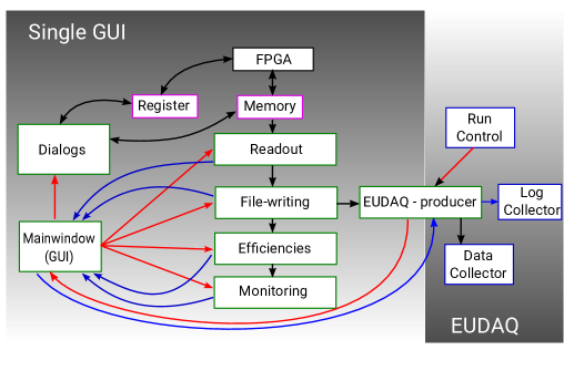
This approach determined the core architecture of EUDAQ [6] which remains today: centralised but distributed core components that communicate with so-called Producers via a custom TCP/IP-based protocol. In this scheme, the latter are responsible for implementing an interface to the individual hardware components, controlling the devices’ states and feeding the data into the central data collection unit. Both the beam telescope detector planes and the DUT use the same interface, thus making the framework flexible and independent of any specific hardware. The framework architecture is described in more detail in Section 2.
Historically, the most prominent application of EUDAQ is the DAQ of the EUDET-type pixel beam telescopes [7]. They are based on Mimosa26 sensors [8] as telescope planes and a custom-designed trigger logic unit (TLU), the EUDET TLU [9]. Today, the EUDET-type beam telescopes are accessible as common infrastructure at test beam facilities all over the world. This broad availability of beam telescopes combined with the ease-of-use, extensive documentation and user-focus of EUDAQ outlined in Section 3 has led to a large number of successful EUDAQ-based test beam campaigns in the last decade: in Section 4, eleven applications from a wide range of communities are described in more detail.
Since the early days of mostly user-driven development, EUDAQ has been moved to a collaborative development model with several active contributors. New features as well as many behind-the-scenes changes such as continuous integration methods paved the road towards the second major version of EUDAQ as briefly outlined in Section 5.
2 Framework Architecture
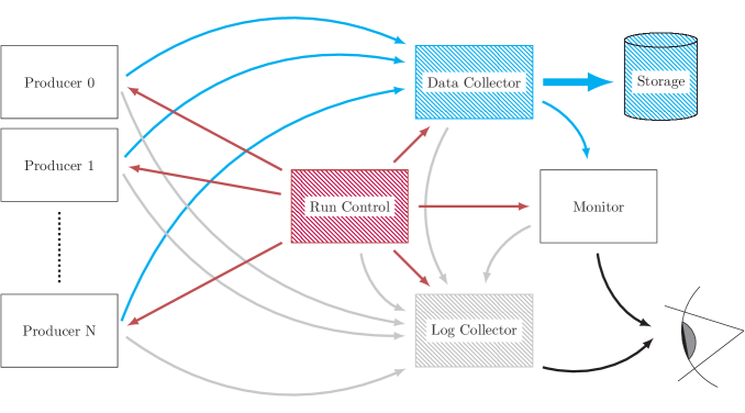
The EUDAQ framework is split into a number of different processes, usually running on several different computers connected via LAN, and communicating using a custom TCP/IP protocol, indicated by arrows between the components in Figure 1. The framework is written in C++, with minimal external dependencies, in order to ensure maximal portability. It uses POSIX threads for concurrency and POSIX sockets [11] for inter-process communication over TCP/IP.
There are three separate channels for sending different types of information to the individual EUDAQ processes: the command, the data and the log channel. In the following, a brief overview of the framework architecture and its concepts is given in Section 2.1, and the individual communication channels are introduced in more detail in Sections 2.2, 2.3 and 2.4. The architecture overview is complemented by a description of the online monitoring tool in Section 2.5 as a crucial part of the user interface.
2.1 Overview & Concepts
A central Run Control provides an interface to the user for controlling the DAQ system. The Run Control monitors the state of all other processes and sends them commands to start and stop a run, configure the components etc. using the command channel indicated by the red arrows in Figure 1. Here, run indicates a continuous period of data taking with typical durations ranging from a few minutes to several hours. Runs are divided into so-called events, which represent the data from all participating devices corresponding to one trigger. Triggers are synchronised between different devices at the hardware level.
Each process of the DAQ that produces data is controlled by a Producer. The EUDAQ Producer class provides a standardised interface to the rest of the framework for receiving commands and sending data and log messages. A Producer should send one event for every trigger. Each event consists of a standard header containing the run number, the trigger number and some other status information, along with the unprocessed raw data from the sensor. If a Producer has no data for certain events for example a small sensor that does not register a hit for every trigger, then it should send empty events (see Section 4.11). In addition to these standard events, each Producer must also send special beginning-of-run and end-of-run events at the start and end of each run respectively. The beginning-of-run event includes the configuration data for the run, ensuring that this information is always available with the collected data. For devices that generate data much less frequently or triggerless data, for example temperature sensors, motor stages (see Section 4.7 or 4.10) or other environment monitors, EUDAQ provides an alternative base class called Slow Producer. However, it is encouraged to use the standard Producers whenever feasible, since the strong synchronisation of events provided helps to ensure data integrity.
The Data Collector receives data as EUDAQ Event objects from all data-generating processes over the data channel as shown by the blue arrows in Figure 1. It collates and organises them such that event data from all Producers is ordered and synchronised, and then for each trigger it combines all the relevant events and writes them to disk (Storage in Figure 1). Because all Producers send one event for every trigger, along with the beginning and end of run events to mark the runs, the synchronisation between Producers to be kept simple, and any problems can be caught and rectified as early as possible. During event building the Data Collector ignores the absence of events from Slow Producers, which are distinguished from the usual Producers by the type information that is communicated during the initial connection. By default, the data files are just the serialised EUDAQ Event objects, consisting of a common header with run number, trigger number etc. and the raw binary data provided by the respective detector. By directly recording the raw detector response without online processing, all initially available information is retained and the risk posed by possible mistakes in the intermediate data processing code is mitigated. These architectural decisions have proven to provide a high degree of stability and confidence in the integrity of the collected data. If required, EUDAQ may also be configured to write in various other formats, such as the LCIO format [12, 13] or its own StandardEvent format.
Log messages from all processes are collected centrally in the Log Collector, using the dedicated log channel indicated by gray arrows in Figure 1. This provides a central location for the user to monitor all distributed processes for any unexpected warnings or errors. The Online Monitor reads the output data file and generates a range of plots to help the user verify that the system is operating properly.
Data is serialised using a simple EUDAQ-specific binary format. The primitive types like different-sized integers, floats etc. are serialised as a sequence of bytes using little-endian format even on big-endian CPU architectures, so that the data is compatible between different machine architectures. Strings are serialised using a 32-bit length indicator followed by the contents of the string interpreted as bytes. A range of standard types, such as std::vector and std::map are also handled by EUDAQ, using a similar scheme. Classes defined in the EUDAQ code base, or by the user, are made serializable by inheriting from the Serializable base class, and by implementing the virtual Serialize function and a constructor that takes a single Deserializer instance. In most cases, the implementation is as simple as writing each member variable to the Serializer in the Serialize method, and reading them in the same order in the constructor. All member variables of a Serializable class must also be serializable – either by inheriting from Serializable, or being explicitly handled by the Serializer class.
2.2 Command Channel
The command channel is controlled by the Run Control component. All other components are connected to the command channel in order to keep track of the current state of the DAQ system. Components that communicate with the Run Control must inherit from the CommandReceiver class, which handles the reception of the command messages and calls the corresponding member functions. When receiving a command from the finite state machine of the Run Control, the component must execute the requested state transition and respond with its new state.
This allows the Run Control to monitor the states of individual components, and to define the global machine state. Messages on the command channel are kept simple, consisting of a single string command with an optional string parameter. This is encoded into a single string message, separated by a null byte if the optional parameter is present. The individual commands are listed in Table 1.
| Command | Parameter | Description |
|---|---|---|
| INIT | Configuration | Initialise DAQ system |
| CONFIG | Configuration | Configure DAQ for a run |
| START | Run number | Start a new run (and send run number) |
| STOP | n/a | Stop a run |
| RESET | n/a | Reset DAQ system |
| TERMINATE | n/a | Terminate (quit) DAQ |
| STATUS | n/a | Retrieve status of all systems |
| LOG | Log server | Configure log server address |
2.3 Data Channel
The data channel is used to collect all data generated during a run into a single component, where it is written to disk. This component is called Data Collector and acts as receiver for data from any of the Producers participating in the run. Usually this will include the Producer for the telescope DAQ, a Producer for the DUT DAQ, and a Producer for a system providing trigger information. All Producers inherit from the Producer base class, which provides a SendEvent method that the inheriting class should call for each event to be sent to permanent storage.
2.4 Log Channel
At runtime, every process can generate log messages containing information about the state of the component, or any unexpected occurrences. Simple access to the messages during data taking is realised by a central Log Collector, which collects messages from all Log channels.
Every process inherits from the Log Sender class, enabling it to send log messages over the TCP/IP connection to the Log Collector. Each log message is an instance of the Log Message class, which contains the log message, a level such as INFO, WARNING, or ERROR, and a timestamp. Similar to other objects, it derives from the Serializable class, allowing network transmission in the usual binary encoding.
2.5 Online Monitoring
An important feature of the EUDAQ framework is the ability to monitor the incoming data stream online using the Online Monitor, which is provided as a part of the framework. The Online Monitor only uses the information provided in the byte-stream and does not rely on external information. It treats every sensor unit as a plane with hits in x-y coordinates and is therefore ideally suited for pixelated detectors as well as strip-based sensors. For all planes a standard set of histograms is generated, e.g. a hit map both in 1D and 2D and the number of hits per sensor plane. The Online Monitor also implements some basic clustering routines and the possibility to perform hit correlations between individual sensor planes to enable gauging of the alignment between sensor planes and the particle beam already during data taking. Additionally, for each different type of sensor, dedicated histograms can be filled if implemented by the user. Finally, central performance monitoring histograms help to identify potential problems during data taking.
The EUDAQ Online Monitor uses the ROOT framework [14, 15] both for creating histograms and rendering the graphical user interface. The initial release of the Online Monitor has been described in [16], but its performance has been significantly improved and its functionality extended by the integration of various other devices into the EUDAQ framework as will be described in Sections 3 and 4.
3 Integration & Operation
The straightforward architecture of EUDAQ allows new users to quickly integrate existing, hardware-specific DAQ systems into EUDAQ with minimal overhead. Within EUDAQ, each such integrated system is represented by a Producer. The Producer has two roles: to receive commands from Run Control and to send the acquired data to the Data Collector. As such, it provides an interface between the user’s DAQ and the rest of the EUDAQ system. Producers can be implemented by deriving from a provided C++ base class, or by using ctypes-based Python bindings. For both use-cases, documentation as well as several examples are provided [6, 17].
Whenever a command is received from Run Control, a corresponding member function of the Producer is invoked. By providing their own implementations of these functions, users are able to control their device’s DAQ. The possible commands include OnInitialise, which is called once at startup to perform one-off initialisation; OnConfigure, which is called to configure the Producers, and may be called between runs to reconfigure with different settings; and OnStartRun and OnStopRun, which start or stop the acquisition, respectively. For the former two, Run Control includes a list of initialization or configuration parameters and their values, which are retrieved from a plain-text file in order to allow modification of parameters for individual data-taking runs. The latter two require the Producers to respond by sending begin-of-run and end-of-run events, respectively, containing specific flags. As well as ensuring synchronisation of runs between all Producers, these events also contain the full sensor configuration as well as the user-provided configuration parameters. Having this information stored alongside the actual data significantly simplifies the bookkeeping for later offline analysis and reference. A utility program called Magic Log Book can be used to extract run numbers and their associated parameters from collected data files in order to automatically generate a test beam “log book”.
During a run, the data retrieved from a device may be submitted through the Producer’s SendEvent method. The data is expected to be encapsulated in one of EUDAQ’s event formats: usually, this is of type RawDataEvent which is a generic container for blocks of binary data. Additionally, each event can hold metadata which can be useful to record variables relating to device state changes. It is up to each Producer how the raw data is encoded, thus ensuring minimal interference by the data acquisition system and therefore reducing the potential for data corruption. The data are then serialised and sent to the Data Collector.
The Data Collector expects that all devices are synchronised through a hardware signal by a central trigger system and that their respective Producers send data on every single event. Otherwise, the Data Collector generates an error to alert the user of missing data.
While the data are usually written to disk in the device’s native format, for online monitoring purposes and later analysis stages a conversion is usually necessary. To easily integrate into the existing tools provided by EUDAQ, the Data ConverterPlugin system was developed. For each type of RawDataEvent, a converter plugin can be registered. This plugin will be dynamically loaded and used to convert the native raw data into a format which can be parsed by EUDAQ.
Once a Producer, the RawDataEvent format and a Data ConverterPlugin have been developed, the respective device is fully integrated into the EUDAQ system and can seamlessly interact with all its components. At this point users are encouraged to submit their code for inclusion into the EUDAQ software repository [17]. This centralised collection of Producers on the main repository helps prospective users in the detector R&D community by providing examples. Furthermore, the contributors benefit from the continuous integration methods employed in the EUDAQ development process. Through regular automated builds and tests, potential issues can be identified early in the process and mitigated before future releases. As EUDAQ is licensed under the GNU LGPLv3 [1], users are generally welcome to share, modify and contribute to its development. The source code of EUDAQ is hosted on GitHub, where any potential issues or feature requests can be reported through its issue tracking system.
Since interconnection between different platforms and even different architectures is often necessary when performing beam tests, EUDAQ has been developed with interoperability and easy deployment in mind. Using the CMake build system, EUDAQ can be compiled on recent versions of GNU/Linux, MacOS X, and Microsoft Windows using the native compiler tools. The core library and the command-line executables of EUDAQ are self-contained and require no additional external dependencies. Optional components, such as specific Producers, can be enabled at build-time and might have additional dependencies. Commonly, these are Qt [18] for the graphical user-interface (GUI) and ROOT [14, 15] for the online monitoring.
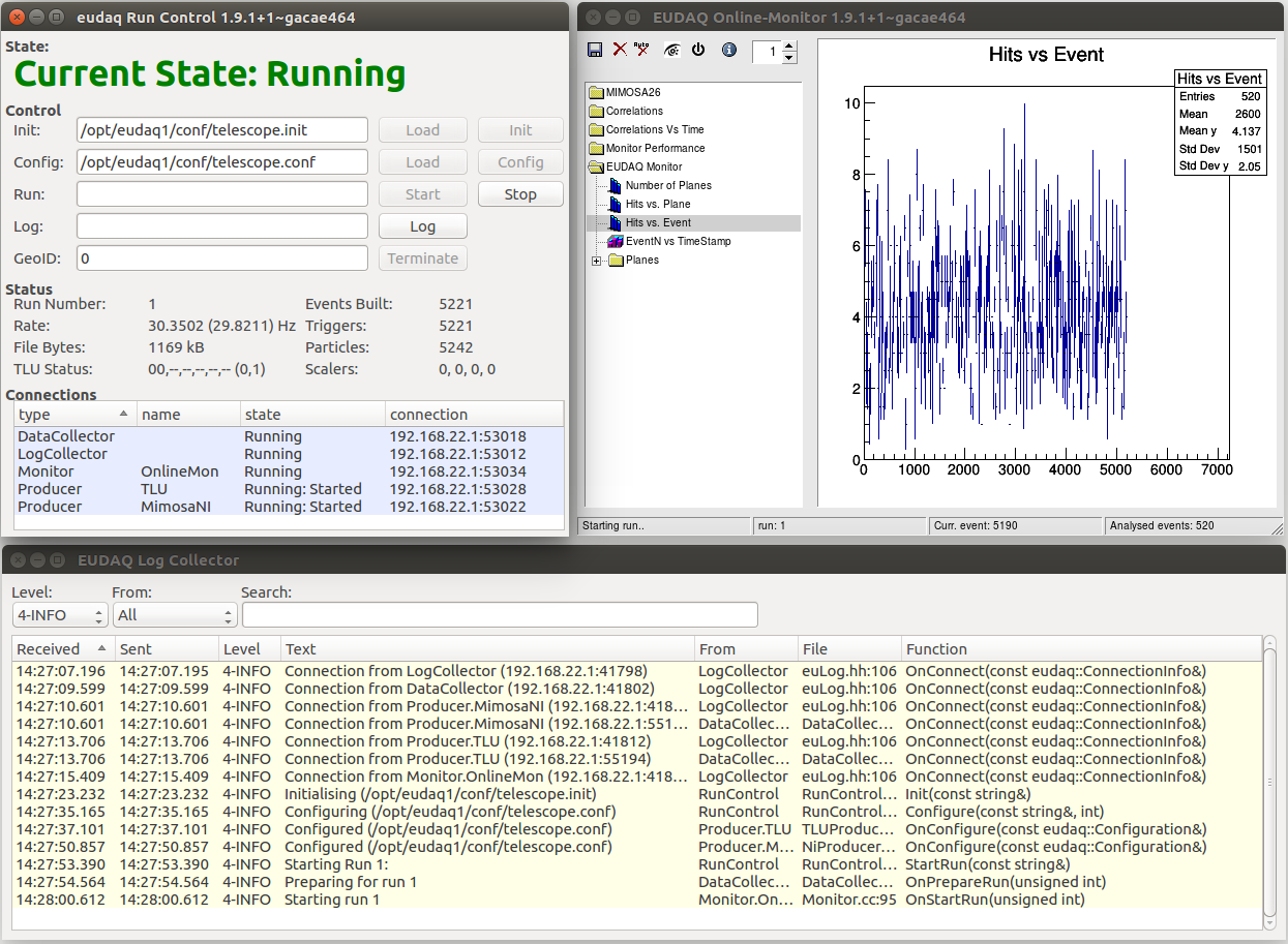
Each individual component of EUDAQ, such as the Run Control, the respective Producers and the Data Collector, run as separate processes communicating with the rest of the system via TCP/IP on configurable port numbers as described in Section 2. Start-up scripts are provided that help to set up typical use-case scenarios. After starting EUDAQ, three windows are displayed as shown in Figure 2: firstly, the Run Control GUI for interaction with the DAQ system and for display of the system state; secondly, the Log Collector window for listing all messages reported within the system, allowing direct searches and live filtering; lastly, the Online Monitor which reads back the data written to disk and generates live-updated histograms. Together these tools provide the detailed online feedback on the performance of the various components that is crucial to the user during test beam operations.
EUDAQ is shipped with many additional tools and ready-made Producers, a complete list of which can be found in the latest manual [19]. Some of the optional components are related to the most common use-case: running within the EUDET-family of beam telescopes. From a hardware perspective, the beam telescopes consist of six planes of Mimosa26 sensors and a triggering system based around an EUDET TLU. Within the EUDAQ framework, these components are represented by their own Producers using the approach of integration into EUDAQ previously described. The NIProducer provides the interface to the Mimosa26 DAQ and is built around the National Instrument (NI) PXIe crate architecture [20, 21]. The TLUProducer connects via USB to the EUDET TLU to initialise, configure and operate it. Operating EUDAQ with the EUDET-type beam telescopes, the trigger or event rate is limited to 2.0 kHz in average. This limit is caused by the data read-out of the EUDET TLU and the Mimosa26 DAQ, but was also sufficient for most of the EUDAQ applications in the last decade (see Section 4).
For all telescope components, converter plugins are provided as part of EUDAQ allowing full online monitoring out-of-the-box. The EUDAQ converter plugins are also utilised by the beam telescope data analysis framework EUTelescope [22, 23, 24] to interpret the raw data written by EUDAQ. EUTelescope provides the user with extensive tools for clustering, alignment, track reconstruction, and data analysis. Thus, the telescope hardware with mechanical user interfaces, the EUDAQ framework, and the reconstruction framework EUTelescope provide a unique infrastructure, which is extendible for any devices under test and covers all aspects of test beam studies.
To summarise, EUDAQ plays a central role in a wide-spread set of test beam tools, including the EUDET-type beam telescopes and the EUDET TLU: today there are seven copies of EUDET-type beam telescopes located at different test beam facilities such as PS and SPS at CERN, the DESY II Test Beam Facility, ELSA in Bonn and ESTB at SLAC. Furthermore, approximately 35 EUDET TLUs were produced and distributed to different R&D groups. Like all infrastructure around the EUDET-type beam telescopes, EUDAQ is highly modular and suited for many use-cases as shown in the following chapter.
4 Applications
EUDAQ is used by a large variety of detector systems. Many detector prototypes and DAQ systems today provide an integration with the EUDAQ system and thus greatly simplify their deployment in test beam campaigns. Especially for users of the DESY II Test Beam Facility [25], due to the close integration of the EUDET-type beam telescopes as well as the EUDET TLU described in Section 3, EUDAQ has proven to be a valuable component of the test beam infrastructure. In the following, several integrations of detector prototypes with the EUDAQ system are presented in alphabetical order. Special attention is paid to the different requirements of the detector systems and the different approaches of integration into the EUDAQ framework.
4.1 ALICE Inner Tracker System: Development of MAPS
The ALICE experiment [26] at the LHC is undergoing a major upgrade in the second Long Shutdown of the collider (2019–2020). During this upgrade, the Inner Tracking System (ITS) of ALICE will be completely replaced by a new silicon pixel detector. This new detector consists of seven layers of Monolithic Active Pixel Sensors (MAPS) designed specifically for the upgrade [27]. This new sensor, called ALPIDE (ALICE PIxel DEtector) [28], is a large pixel detector with 1024 512 pixels with a pitch of . The sensor can be thinned down to a total thickness of .
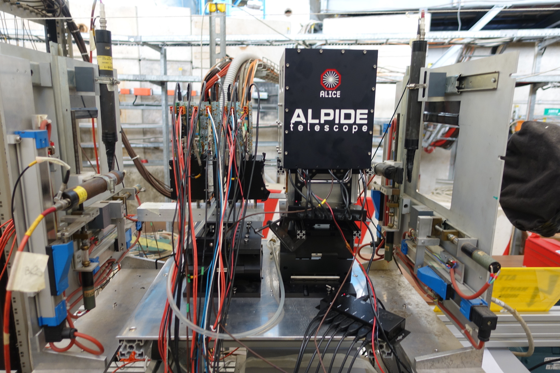
The ALPIDE sensor has been developed in a long prototyping and testing phase before arriving at the final design. First prototypes of the detector have been characterised in test beam measurements as early as 2013. This so-called Explorer chip [29] featured an analogue output, a small active matrix with approximately 12k pixels and has been tested using reference tracks from the EUDET-type beam telescope. In a next step, slightly larger prototypes with approximately 32k pixels and an ALPIDE-like architecture [30] were tested first with an EUDET-type beam telescope and later on with ALPIDE prototype-based telescopes as shown in Figure 3. All these different setups have been integrated and were operated using the EUDAQ framework.
In order to efficiently conduct the many test beam campaigns for the development of the ITS with a total of approximately runs, a high degree of automation and reliability was required. This has been achieved by implementing the necessary key features into the EUDAQ framework: automatic change of detector configuration at the end of a run; timestamp and data integrity control directly in the EUDAQ Producer; the ability to fully reconfigure the hardware during the run from within the Producer; and control of external equipment such as power supplies, rotary and translation stages as well as the cooling unit.
4.2 ATLAS Inner Tracker: Pixel Detector R&D
The ATLAS pixel detector is the innermost part of the tracker subsystem of the ATLAS experiment [31]. After the initial installation the pixel detector consisted of three barrel layers and two end-caps with three disks each. Its modules consist of a planar silicon n+-in-n sensor tile to which 16 FE-I3 readout chips are bump bonded. The top of the sensor has a flexible PCB attached which hosts an aggregator chip, which multiplexes the individual data streams from the ASICS. The default pixel has a size of and the detector has achieved a resolution of in the radial direction () and along the -axis [32]. The BAT telescope [33] based on silicon-strip detectors was used during the R&D and the qualification phase [34, 35]
In 2010 it was decided to amend the detector with an additional layer of pixel detectors, the so-called Insertable B-Layer (IBL) [36] to improve tracking robustness and b-quark tagging. At the beginning of the sensor oriented research effort FE-I3 [37] based modules were used. Those were operated by the laboratory test system TurboDAQ [16], which has been fully integrated into the EUDAQ framework in order to allow efficient testing of the chips using the EUDET-type beam telescopes. As the development of the IBL progressed, both a new readout ASIC, FE-I4 [38], and a new generation of readout systems were introduced and integrated into the EUDAQ framework right from the beginning. In the USBpix Gen2 readout board [39] the incoming data was multiplexed and transmitted by a single Producer, while with the next-generation USBpix Gen3 [40, 41] the readout was fully asynchronous using the so-called STcontrol software [42]. Through this tool, data were copied from the DAQ board to the computer and sent by the Producer simultaneously. A single CommandReceiver is instantiated while each connected board has its own DataSender which are instantiated once the number of boards is known from the configuration. An alternative readout system used for FE-I4 based modules during test beams is the HSIO-2 system which also provides a Producer.
Different pixel sensor technologies were developed and qualified for the ATLAS IBL in multiple test beam campaigns at CERN and DESY: slim-edge thin n+-in-n planar and, for the first time-use in high-energy physics, 3D sensors [43]. The radiation hardness of these sensors beyond the required was successfully demonstrated. The test beam results obtained with the different readout systems and sensors [44] may be found in the summary paper [45] and the production report [46].
With the IBL installed and operating, the R&D of ATLAS pixel detector modules continued with a focus on the HL-LHC upgrade. A new all-silicon tracking detector [47] will replace the current inner detector and the pixel part will consist of five layers and corresponding end-caps. Pixel modules with slim-edge and radiation-hard thin n-in-p planar and 3D sensors were prototyped using the FE-I4 readout chip and tested up to fluences on the order of and beyond [48, 49, 50]. Two prototypes of readout ASICs, FE65-P2 and RD53A [51], have been characterised in test beams and for the current stage of testing, the RD53A is used. In order to operate the new generation of readout chips also new readout systems YARR [52, 53] and BDAQ53 [54] have been developed. They profited from experience with the previous DAQ generations and both are providing an EUDAQ Producer.
Two additional developments originated from within the ATLAS Pixel Detector R&D: Firstly pyBAR software for the readout of FE-I4 ASICs has been developed as an alternative DAQ software using PYTHON. This has been used with several readout boards including USBpix Gen2 and USBpix Gen3 boards. It was initially developed to investigate chip tuning methods [55] and then used for hybrid pixel detector R&D [56] ranging from single-chip readout for sensor characterization [57] to multi-chip readout for operation and testing of larger-scale detectors [58, 59, 60]. The pyBAR software uses PYTHON bindings to integrate into the EUDAQ framework and to provide a dedicated Producer which enables the complete control of pyBAR via the EUDAQ Run Control.
A second development was an additional telescope plane consisting of a FE-I4 based module read out by a USBpix board. This has been added to the EUDET-type beam telescopes to provide a reference detector which allows region-of-interest triggering and to provide track time stamps with a granularity of [61].
4.3 ATLAS Inner Tracker: Strip Tracker R&D
For the High-Luminosity LHC the ATLAS experiment [31] will replace the current tracking system with an all silicon detector, the Inner Tracker (ITk), consisting of inner pixel layers and outer strip layers. The ITk Strip detector will be composed of four barrels and six end-cap disks on each side, with a total silicon area of approximately 165 m2. The basic building unit is the strip module, which consists of an -in-p silicon sensor, one or two hybrids that host the front-end ASICs, and a power board, which provides the power for the read-out chips and monitoring functionalities. The hybrids and the power board are glued directly on top of the silicon sensor [62].
Starting from 2014, several prototype modules have been tested during a series of test beam campaigns at DESY, CERN and SLAC, using EUDET-type beam telescopes [63]. In 2017 the DAQ was upgraded to EUDAQ version 2 for subsequent test beams [64]. The readout cycle of the DUTs corresponds to the LHC bunch-crossing frequency at and is thus much shorter than the rolling shutter readout of the Mimosa26 sensors of EUDET-type beam telescope. In order to select only tracks passing within one readout cycle of the DUT, the integrated FE-I4 plane described in Section 4.2 has been used. An entire barrel module was irradiated to the full expected dose at the HL-LHC and was characterised in 2016, which provided valuable information regarding the future performance of the modules at the end-of-lifetime of the HL-LHC.
The ITk Strip DAQ (ITSDAQ) used to operate the detector prototypes runs on an FPGA which performs the trigger-busy-handshake with the EUDET TLU. The so-called ROOT Producer has been developed to provide the interface between the EUDAQ configuration file and ITSDAQ [65]. Two data streams are sent independently to the EUDAQ Data Collector: one containing the hit information and timestamps from the front-end ASICs, and another containing the timing, trigger and control information from the FPGA. Two converters have been implemented in EUDAQ for the individual streams. It has been observed that the hit information data stream sometimes exhibits de-synchronization problems which can, however, be corrected offline during the analysis of the raw files by comparing the timestamps in the two streams on an event-by-event basis. To mitigate further problems with de-synchronization, in the latest test beam campaigns an automatic check has been implemented and deployed in ITSDAQ which allows to directly identify de-synchronised events and re-synchronise the data online.
4.4 Belle II Vertex Detector: Development of DEPFET Sensors
The Belle II experiment [66] is a new general purpose detector operated at the new Japanese Super Flavor Factory, SuperKEKB. The new machine, working at the intensity frontier, collides electrons against positrons at intermediate energies of but delivering ultra-high luminosities, and is expected to reach in the early 2020s. Belle II is searching for physics beyond the standard model in B, D and decays through precision measurements and studies of highly suppressed or forbidden processes [67].
The main task of the Belle II vertex detector (VXD) is to provide an accurate measurement of the impact parameters that allow the precise determination of the position of the vertices of the short-lived particles. The VXD consists of two layers of DEPFET pixel detectors (PXD) and four layers of double-sided silicon strip sensors (SVD). The pixel detector is composed of eight million DEPFET pixels with in and 55- in and operates at a readout frame rate of . The reduced thickness of the sensitive volume of and the minimal services and support structures sum up to a total overall material budget of 0.21 X0.
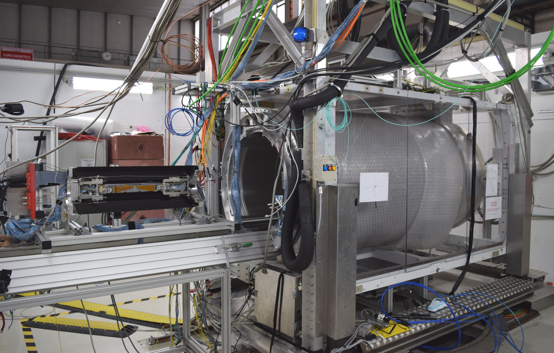
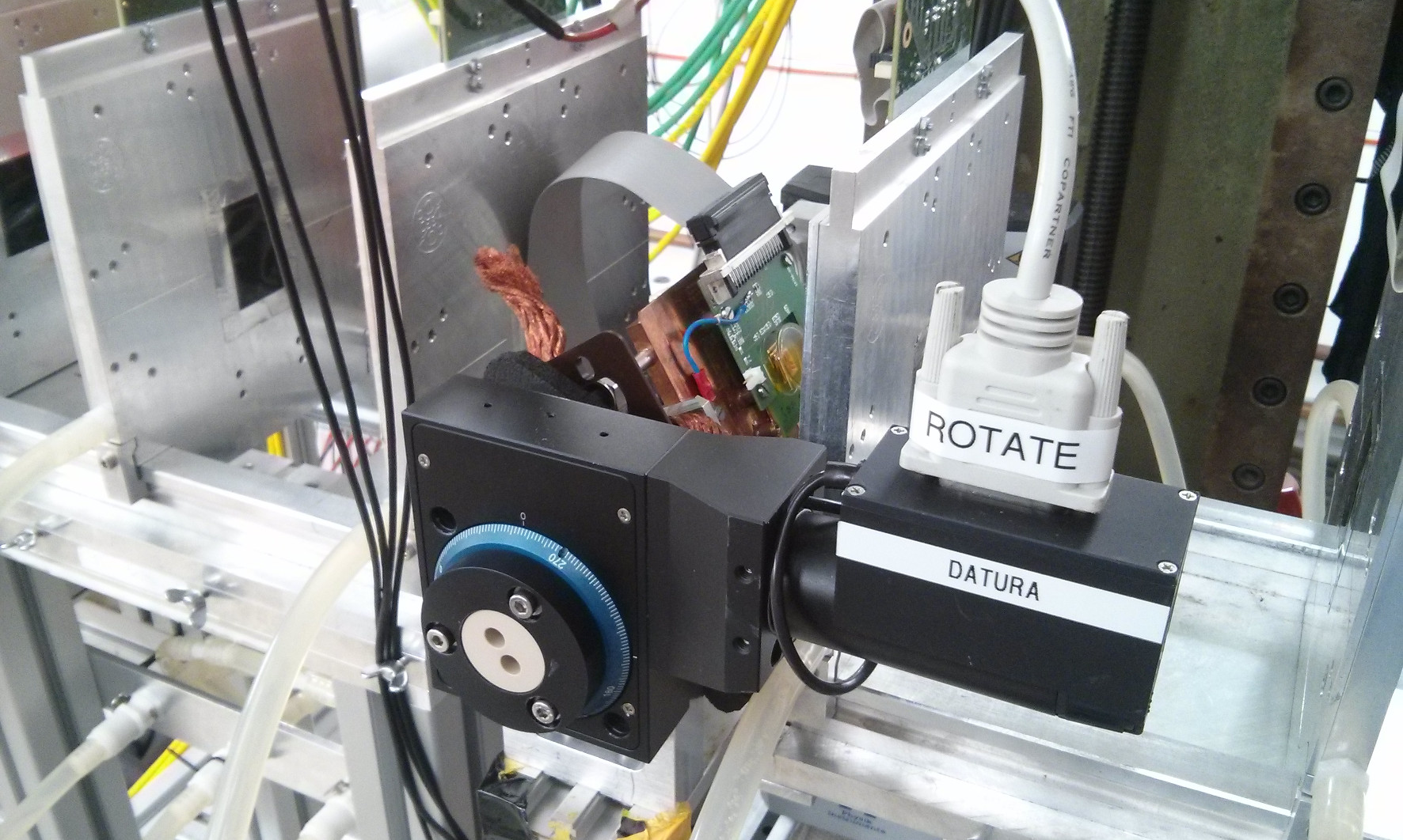
The final PXD detector modules are the result of more than 10 years of testing and prototyping. The DEPFET collaboration was the first user to perform a complete integration of the devices under test into the EUDET-type pixel telescope [68] including the integration into EUDAQ. Early PXD standalone test beams with small scale prototypes focused on measuring the intrinsic spatial resolution and hit efficiency of thick sensors and provided data to validate the detector simulation in the Belle II software [69]. Several combined VXD and standalone PXD test beam campaigns have been successfully performed [70, 71] at the DESY II Test Beam Facility using EUDET-type telescopes as shown in Figure 4.
In order to increase the data taking efficiency for prototypes with small sensitive area, the DEPFET collaboration used the region-of-interest (ROI) trigger described in Sec. 4.2 to select only tracks traversing the sensitive area of the device under test. The availability of this FE-I4 reference plane for triggering and timing was valuable also for a test beam with full size () and thick DEPFET sensor at DESY in November 2018. The FE-I4 hit data was read out with pyBAR (c.f. Section 4.2) and sent to the EUDAQ Data Collector in order to identify tracks with a resolution of which allowed the measurement of the hit efficiency of the DEPFET devices.
Finally, a main requirement for the Belle II VXD design was to minimise the material budget as much as possible in order to reduce multiple scattering of impinging particles. The magnitude of the effect depends on the local material budget measured in units of the radiation length X0. The DEPFET collaboration developed a framework to compute high resolution images of the material budget of planar objects installed in the center of EUDET-type telescopes [72], similar to the material budget imaging described in Section 4.10. High resolution images of mechanical prototypes of Belle II PXD and SVD ladders were obtained in a test beam at DESY in 2015 and were used to validate the Geant4 model of the Belle II VXD.
4.5 CALICE: R&D of Electromagnetic & Hadronic Calorimeter Prototypes
The Silicon Tungsten Electromagnetic Calorimeter (SiW-ECAL) and the Analogue Hadronic Calorimeter (AHCAL) are two CALICE prototypes of high granularity calorimeters for future colliders. Both entered the engineering phase of prototyping where the main technological challenges, such as compactness, reduction of power consumption and embedding of the very-front-end (VFE) in the active layers, are addressed.
The SiW-ECAL technological prototype [73] consists of thin layers of silicon sensors (300-) as active material alternated with tungsten plates as absorber material. The active layers are made of a matrix of silicon sensors segmented each in matrices of squared pixels with a pitch of . The VFE consists of 16 SKIROC ASICs [74] that have been designed for the readout of silicon PIN diodes. The AHCAL prototype consists of detector layers that are made from units, each equipped with 144 scintillator tiles () individually read out by SiPMs. The VFE consists of four SPIROC ASICs [75].
The prototypes use different DAQ systems. While the AHCAL readout is based on a Labview DAQ, integrated into the EUDAQ framework by means of a Producer, the independent Calicoes software [76], based on the Pyrame framework [77], has been developed for control and data acquisition of the SiW-ECAL. Both prototypes are self-triggered and are designed for the ILC [78] timing structure with bunch trains of high activity interspersed with significant periods without beam which are used for readout and lead to dead time. Therefore the synchronization of the active periods of the detectors is very important for test beams.
The hardware synchronisation was ensured by two clocks – and , derived from a single clock generator – and a shared signal to control the acquisition. The EUDAQ framework was used to integrate the two separate DAQ frameworks of the prototypes. EUDAQ producers receive data from each subsystem via a TCP/IP socket connection and send them to the Data Collector to combine them into one event in LCIO format by correlating their timestamps. LCIO collections are used to separate the individual subsystems.
In 2016, test beams of the AHCAL prototype with an externally-triggered EUDET-type beam telescope were conducted at the DESY II Test Beam Facility. Hardware synchronization was provided by an EUDET TLU running in the trigger-handshake mode. The trigger signals were recorded by the AHCAL DAQ hardware to allow correlation with the self-triggered hits from the AHCAL. Events were then combined on the basis of the trigger number and converted to LCIO. The EUDAQ online monitor provided a visual verification of the synchronization via the spatial correlation between the detectors.
EUDAQ was also used for a combined test at the CERN SPS in 2017 of the AHCAL prototype with the CMS HGCAL prototype described in Section 4.7. For this, an additional EUDAQ Producer was developed to control and read out Delay Wire Chambers (DWCs) using a CAEN TDC VME module. Similar to the preceding test beams, events were built in EUDAQ using the trigger numbers recorded by all participating devices.
Since the first test beam with EUDAQ, the AHCAL group has adopted EUDAQ as DAQ framework for most test beams including the integration with the AIDA-2020 beam telescopes and the TLU. Multiple tests were performed in different test beam campaigns, which were crucial in the development of EUDAQ2, supported by the AIDA-2020 project work package for common test beam DAQ developments. The CALICE collaboration has decided to encourage all participating groups to use EUDAQ for new common test beams [79].
4.6 CLIC Vertex & Tracking Detectors: Pixel Detector R&D
The CLICdp collaboration studies available silicon pixel detector technologies, evaluates their tracking performance and identifies promising candidates for the construction of CLIC tracking and vertex detectors. Low material budget, small pixel pitch for a good spatial resolution and a few-nanoseconds timing resolution are needed to satisfy the physics requirements and cope with the experimental conditions in the CLIC detector.
In the context of this study, the Timepix readout ASIC [80] was used as a test vehicle to study the tracking characteristics of pixel sensors of various thicknesses and different polarities in order to develop simulation models to estimate the performances of future prototypes with smaller pitch and thinner substrate as required for CLIC. A series of sensors with thickness varying from to , with both polarities, was produced and a systematic characterization of their tracking properties using the EUDET-type telescope, the EUDAQ software and custom EUDAQ Producers was performed.
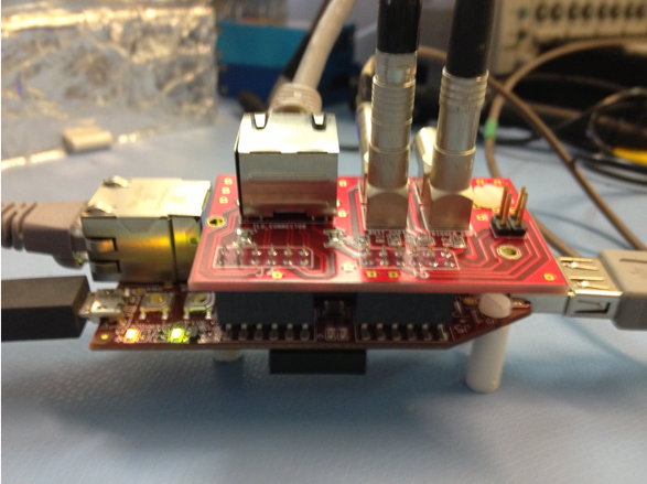
For initial studies, the proprietary readout system FITPix [81] was used. The pre-compiled libraries as well as the headers were provided by the Timepix/Medipix collaboration to allow interfacing the system with EUDAQ, but no modifications of firmware or software were possible. With the frame length of the EUDET-type beam telescopes of up to being much smaller than the configured frame duration of the Timepix, a simple trigger-busy scheme providing only one track per trigger issued would have severely limited the data rate. To mitigate this, an intermediate hardware interface between the TLU and the FITPix readout hardware, The Man-In-the-Middle TLU Unit (MIM-TLU) show in Figure 5, was designed. It consists of a Spartan6 FPGA evaluation board and a custom shield board providing the interface to the RJ45 DUT connection of the TLU and the Trigger-Busy interface of the FITPix. It allows the duty cycle of the Timepix detector to be maximised by accepting a configurable number of triggers from the TLU for each frame of the Timepix. The events were synchronised based on trigger IDs and the duty cycle of the system could be improved from to via the integration of up to 100 TLU triggers.
The Timepix EUDAQ Producer also provides interfaces to a Keithley High-Voltage power supply through a GPIB-USB interface and to a rotation stage via RS232 in order to perform automated threshold, bias and incident angle scans. The scan parameters were provided to the producer through the standard EUDAQ configuration files and the information on the system configuration was encoded in the header of the EUDAQ data files for further reference. The Magic Log Book tool was used to extract the conditions for each run and automatically populate the test beam log with the appropriate information. Finally, a decoder for online monitoring and integration to the EUTelescope reconstruction framework was developed in order to verify data quality during test beam and to perform reconstruction of the events for further analysis. More than nine weeks of continuous test beam was performed with this setup and the substantial amount of data acquired lead to multiple publications and PhD theses [82, 83, 84, 85, 86].
Following the successful experience with the Timepix integration, a Timepix3 producer was created and the FITPix system was replaced by the SPIDR readout [87]. The Timepix3 uses a data-driven acquisition model with no dead time for the readout and no additional hardware was required for operation with the EUDET-type telescope. Similarly, a Producer for the CLICPix ASIC [88] was produced, based on the ASIC system. Results of the Timepix3 and CLICPix characterisation can be found elsewhere [89].
4.7 CMS High Granularity Calorimeter for HL-LHC
For High-Luminosity LHC the CMS experiment will replace its existing end-cap (1.5<<3) calorimeters with a sampling calorimeter based on a mixture of silicon sensors in the highest radiation regions, and scintillating tiles with on-tile SiPM readout. The resulting High Granularity Calorimeter (HGCAL) will have unprecedented readout and trigger granularity for particle showers, facilitating particle-flow analyses to ensure good energy resolution and particle identification in the very high pileup and radiation environment expected [90]. The HGCAL will be installed during Long Shutdown 3 of the LHC, foreseen around 2024-2026. A series of beam-tests was planned in 2015, in order to validate the feasibility of the technically-challenging HGCAL design and to compare its simulated performance with that found in reality.
For the first small-scale tests of prototype hexagonal silicon modules at FNAL and CERN in 2016 [91] a proprietary DAQ system [92] was sufficient. Larger-scale tests were planned for 2017/18 using new DAQ components. In order to allow synchronous data taking with other hardware, EUDAQ was selected as central DAQ system due to its configurability, scalability, integrated Data Quality Monitoring (DQM), ease of use and relatively simple integration with different hardware. Initially three dedicated EUDAQ Producers were implemented: for the so-called RDOUT boards using the IPbus protocol [93], for CAEN v1290 TDCs, and for CAEN v1742 digitisers. The latter were incorporated for the readout of various beam-characterizing detectors at CERN such as Delay Wire Chambers (DWCs) [94], threshold Cerenkov counters and timing devices.
Following the recommended procedure, DataConverterPlugins for the online reconstruction and analysis of the HGCAL data were developed. The converted data were then visualised by suitably modifying the EUDAQ DQM to correctly display the hexagonal pixels of the CMS HGCAL modules. Independently-developed systems using EUDAQ for the readout, such as the CALICE AHCAL presented in Section 4.5, could be integrated into the tests with little modifications to the triggering logic at the hardware level. It is noteworthy that for the 2018 HGCAL test at DESY, the integration of the EUDET-type telescopes and X-Y stage was straightforward and allowed exploiting the pre-installed telescope Producer, Slow Producer and the TLU provided at the DESY II Test Beam Facility.
Using EUDAQ as central DAQ framework, systems ranging from a single 128-channel hexagonal silicon module, to 94 modules plus the 39-layer 2018 CALICE AHCAL prototype, were successfully tested in beams at DESY and CERN in 2017 and 2018 for a total of more than two months. The final test at CERN in October 2018 was performed with a prototype comprising a total of channels. The EUDAQ-based DAQ was reliable and sufficiently simple to be operated by 40 trained shifters in total. Data from up to four EUDAQ producers, the three mentioned previously plus one for the AHCAL, were acquired at a rate of around , limited by the DAQ hardware. In total, more than 6 million pion, electron and muon events were recorded for analysis. This in-built DQM proved very useful for ensuring good data quality, as can be seen in Figure 6. Data are currently being analyzed, but initial indications are very positive.

4.8 CMS Pixel Detector: Test Beams for the Phase I Upgrade
In the year-end technical stop 2016/2017, the CMS experiment has replaced its pixel detector with a new detector system in order to withstand the higher instantaneous luminosity of the LHC of expected for the following years of operation [95]. This so-called Phase-I Upgrade comprised, among other changes and improvements, of a new front-end ASIC, also referred to as readout chip (ROC). This chip is an evolution of the ROC used in the first pixel detector for CMS, implementing several enhancements to allow for higher particle rates and occupancy. The chip is fabricated in a radiation-hard process and features a pixel pitch of and a matrix of pixels.
Many test beam campaigns have been conducted in order to test new ROC versions, to verify design changes and to ensure good performance of the final detector modules [96, 97]. These measurements have been conducted at the DESY II Test Beam Facility using positrons from the DESY II synchrotron. Assemblies with the different ROC versions have been operated as DUTs and were placed between the two arms of an EUDET-type pixel beam telescope as shown in Figure 7. In addition to the DUT in the center of the beam telescope, a second ROC was placed downstream at the end of the beam telescope as a timing reference. This is necessary for efficiency measurements due to the rolling-shutter readout of the telescope detectors with an integration time of and the resulting track multiplicity in the beam telescope.
A dedicated readout system has been designed and built for the CMS pixel detector ROC family, consisting of a custom-designed FPGA-based readout board and the software library pxarCore [98]. The system is capable of operating single ROC assemblies as well as full detector modules and has been used for test beam measurements and for the qualification of all final detector modules produced.
The software library strictly separates user inputs from hardware calls by means of a hardware abstraction layer (HAL). This concept has allowed a stable application programming interface (API) to be provided to various users and developers of user interfaces while major changes could be implemented on firmware and HAL-level without entailing additional changes to user software or breaking compatibility with older versions. Using this interface, an EUDAQ Producer (CMSPixel) was written which parses the configuration parameters obtained from the EUDAQ Run Control and calls the appropriate API functions of the pxarCore library. Providing a Data ConverterPlugin for EUDAQ ensured full integration of the detector into the online monitoring system and allowed supervision of basic detector parameters as well as correlation with telescope planes during data taking.
The test beam activities and results have been summarised in a publication [97], and the detector was successfully built, commissioned and is in operation since the LHC year-end technical stop 2016/2017. The test beam setup and its EUDAQ integration has also been used for measurements studying the performance of the ROC under the influence of radiation-induced damage [99].
In addition to the comprehensive test beam campaigns for the characterization of the new readout chip, measurements with full CMS Phase I pixel detector modules have been performed [100]. Here, a telescope consisting of four detector modules with 16 ROCs each has been operated using the same readout electronics. In order to correlate the data from the different planes and to orchestrate the start and stop of a run, the EUDAQ Run Control was used together with four individual CMSPixel producers, one for each telescope plane. Owing to the flexibility of the EUDAQ framework and the underlying DAQ library, this did not require any changes to the code but provided an out-of-the-box experience for data acquisition of the new telescope, including online monitoring capabilities.
4.9 CMS Outer Tracker: Module Qualification in Test Beams for Phase 2
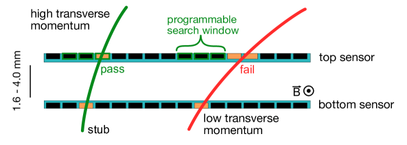
For the HL-LHC, the CMS experiment will substantially upgrade its tracking detector [101]. The all-new CMS Phase-2 tracker will consist of an Inner Tracker (IT) based on silicon pixel modules and an Outer Tracker (OT) made from silicon modules with strip and macro-pixel sensors. In the Outer Tracker, so-called modules will be utilised, which will provide input from the OT to the CMS L1 trigger. The modules are composed of two closely-spaced silicon sensors, which are read out by a common front-end ASIC, correlating the signals in the two sensors. With the T field of the CMS magnet, tracks from charged particles are bent, with the helix radius depending on the of the particle, as shown in Figure 8. Hit pairs corresponding to signals compatible with particles above the chosen threshold are called stubs and are sent to the L1.
Two different module types are foreseen for the OT: 2S modules comprising two strip sensors, and PS modules, where a strip sensor and a macro-pixel sensor are used. The latter are deployed at radii from mm, the former at radii larger than mm.
Four successful test beam campaigns investigating Outer Tracker prototype modules have been performed at DESY and CERN in 2017 and 2018 with the EUDET-type beam telescopes. The FPGA running the CMS OT DAQ performs the full trigger-busy-handshake protocol with the EUDET TLU. A custom EUDAQ Producer has been developed and interfaces the CMS OT DAQ with the EUDAQ Run Control. Whilst the initial configuration of the CMS modules is performed separately, the Producer sends the hit data of both prototype sensors to the Data Collector. Furthermore, parameters from the front-end ASICs such as TDC or stub information are added to the individual EUDAQ events for the track reconstruction and subsequent analysis.
4.10 Material Budget Imaging: Using Scattering Angles to Gauge Material

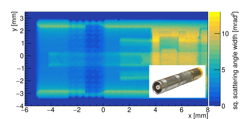
The material budget is the ratio of the thickness of a sample and its radiation length X0. One of the main concerns when designing tracking detectors for particle detectors is to minimise this value in order to reduce the effect of multiple scattering which degrades the achievable track resolution of the detector. Combining the EUDET-type telescopes as high-precision tracking devices and the moderate test beam momenta of the DESY II Test Beam Facility, a high spatial resolution for material budget imaging measuring the scattering angle of each particle can be achieved. This methodology has been used by different groups and experiments to gauge the material budget of detector prototypes or other objects, for example [72, 102, 103].
Using this method, structures of devices can be resolved in a two-dimensional image covering the Mimosa26 active area or even in three-dimensional tomographic images by rotating the sample under test [104, 99]. In this case a large amount of recorded particle tracks is needed to reach a reasonable resolution and contrast in the images. With the particle fluxes in the order of achievable at the DESY II Test Beam Facility, it is required to employ automatic data taking over longer time periods. EUDAQ and the DAQ of the EUDET-type beam telescopes have shown to perform stably when conducting measurement campaigns overnight using the automatic-next-run option.
The and linear stages can be used in order to explore samples larger than the active area of the Mimosa26 sensors. The rotational stage offers the possibility to perform tomographic studies. For this, the control over the different motor stages was implemented in EUDAQ as a Slow Producer, which allows one-dimensional scans to be performed by defining the scan range in the configuration file. For performing arbitrary two-dimensional scans, multiple configuration files for the respective coordinates can be created. After the completion of a given run, corresponding to one configuration file, the subsequent file is automatically loaded by the Run Control. This feature is extensively used for the three-dimensional tomographic imaging technique.
Owing to this fully automated data taking as well as the possibility to record even larger areas than the size of the Mimosa26 active area by stitching images, this technique is a valuable tool to gain insights into the material budget of calibration material as well as complex structures as demonstrated in Figure 9.
4.11 Mu3e: Development of HV-MAPS Sensors
The Mu3e experiment will search for the charged lepton flavor violating decay . The low momenta of the decay particles requires an ultra thin pixel sensor with high rate capabilities. Additionally, the continuously decaying muons do not allow for a hardware trigger, demanding a zero suppressed streaming readout of the pixel sensors. High-voltage monolithic active pixel sensors (HV-MAPS) [105] are chosen for the Mu3e tracker, as they offer a high integration level combined with the option of thinning the sensor down to a total thickness of only .
Four HV-MAPS prototype generations have been studied utilizing the EUDET-type telescopes during 14 test beam campaigns at the DESY II Test Beam Facility. The triggerless fast sensor readout poses a challenge for the integration into the triggered EUDAQ framework. A hit is registered and read out in less than , compared to the rolling shutter revolution time of up to of the Mimosa26 sensors. During a single Mimosa26 readout cycle, the timestamps on the MuPix laps 15 times. Additionally, the prototypes are significantly smaller than the Mimosa26 sensors, leading to events without a hit in the MuPix. To avoid several triggers without hit-data, empty blocks are sent to the Data Collector to match the trigger frequency. The full trigger-handshake with the TLU is realised on an FPGA.
A custom Producer, serving as interface between the MuPix DAQ and the EUDAQ Run Control, has been developed. The flow chart of the interaction between the two systems is depicted in Figure 10. The EUDAQ Producer steers the complete MuPix readout and configuration procedure. Error messages, status information and the start/stop/configure signals are forwarded to the MuPix DAQ. The Producer buffers the entire data stream of the MuPix until one TLU trigger is registered, transforms the data into an EUDAQ interpretable format and sends it to the Data Collector.
5 Conclusion & Outlook
EUDAQ has been developed as a common data acquisition software for many different use cases and fulfills several common requirements:
-
•
Flexible and light-weight: EUDAQ is platform independent and can be operated on Linux, Windows or macOS, and comes with as few external dependencies as possible.
-
•
Easy-to use: EUDAQ incorporates well-defined interfaces which allow data sending and control of the user’s hardware and conversion of the data for monitoring or offline analysis.
-
•
Robust data taking: The data taking strategy is to store detector-native raw binary data without additional processing by the DAQ system. This allows to retain all information initially recorded and reduces the risk of data loss through errors in the processing code. The data handling is performed by one central instance and data from different sub-detectors are synchronised on an event-by-event level, ensured by the global busy-trigger communication provided by the EUDET TLU.
Thanks to many user groups continuing to share their code integrating their own devices, EUDAQ now ships with support for many different devices. This both serves as a reference for new users and allows developers to ensure compatibility when modifying core parts of the framework. Over more than a decade, EUDAQ has thus been maintained for production and, at the same time, been constantly developed and improved. The diversity of the contributing user groups is a testament to the collaborative spirit of the test beam community and the central role that the EUDET-type beam telescopes, and in turn EUDAQ, plays. As part of the EUDET-type beam telescopes, EUDAQ was assessed by the community at the “Beam Telescope and Test Beam” workshop in 2018 [2]. From the discussion and survey among the participants, it was concluded that the EUDAQ architecture and development road-map fulfills the test beam user’s needs for the foreseeable future.
During the implementation phase of the AIDA framework [107], EUDAQ became a candidate for a common test beam DAQ, extending beyond its initial goal of serving as system for telescope-based test beams only. In a comparison with other DAQ frameworks such as XDAQ [108], EUDAQ was judged as “greatly simplified, and relies on as few external libraries as possible. EUDAQ is designed to be portable.” Furthermore, recommendation for improvements were collected from the telescope community. These included suggestions such as parallel data streams and the possibility to acquire individual events for each particle or trigger [109].
These requirements led to the development of an improved version of EUDAQ and the new version – called EUDAQ2 – was selected as the common software framework under the work package WP5 within the AIDA-2020 framework [110]. EUDAQ2 breaks with several concepts such as the event-by-event synchronization of devices and is therefore not compatible with Producers written for EUDAQ. It comes with the possibility to run multiple Data Collector instances for decentralised data taking and is therefore more scalable than EUDAQ. Together with the new AIDA TLU [111] a higher trigger rate can be achieved and events can be built either online or offline by synchronizing the individual data streams using their trigger IDs or a common clock. The framework was released in 2017 [64] and has already been applied by the ATLAS ITk Strips test beam group for the first time. Thank to these enhancements EUDAQ has become even more flexible and is ready for testing the next generation of detectors for future experiments.
Acknowledgments
The authors are greatly indebted to their colleagues from the DESY FH division over the last decade, who are essential to successfully maintain and extend this software framework. This work was supported by the Commission of the European Communities under the 6th Framework Programme “Structuring the European Research Area”, contract number RII3-026126. The research leading to these results had received funding from the European Commission under the FP7 Research Infrastructures project AIDA, grant agreement no. 262025. This project has received funding from the European Union’s Horizon 2020 Research and Innovation programme under Grant Agreement no. 654168. The support is gratefully acknowledged. The information herein only reflects the views of its authors and not those of the European Commission and no warranty expressed or implied is made with regard to such information or its use.
References
- [1] Free Software Foundation, GNU Lesser General Public License 3, https://www.gnu.org/licenses/lgpl-3.0.html, accessed: June 2019 (2007).
- [2] J. Dreyling-Eschweiler, et al., Summary and Conclusions of the ’JRA Beam Telescope 2025’-Forum at the 6th Beam Telescopes and Test Beams Workshop (2018). arXiv:1805.09572.
-
[3]
EUDET: Detector R&D towards the International
Linear Collider, accessed: April 2019.
URL https://www.eudet.org/ - [4] J. Aguilar, et al., Infrastructure for Detector Research and Development towards the International Linear Collider (2012). arXiv:1201.4657.
-
[5]
D. Haas, et al.,
JRA1
– Data acquisition system, EUDET-Memo-2006-07 (2007).
URL https://www.eudet.org/e26/e28/e183/e265/JRA1_DAQ_annual2006.pdf -
[6]
E. Corrin,
EUDAQ
Software User Manual, EUDET-Memo-2010-01 (2010).
URL https://www.eudet.org/e26/e28/e86887/e86890/EUDET-Memo-2010-01.pdf - [7] H. Jansen, et al., Performance of the EUDET-type beam telescopes, Eur. Phys. J. Tech. Instr. 3 (1) (2016) 7. doi:10.1140/epjti/s40485-016-0033-2.
- [8] C. Hu-Guo, et al., First reticule size MAPS with digital output and integrated zero suppression for the EUDET-JRA1 beam telescope, Nucl. Instrum. Methods Phys. Rev. A 623 (1) (2010) 480–482, 1st International Conference on Technology and Instrumentation in Particle Physics. doi:10.1016/j.nima.2010.03.043.
-
[9]
D. Cussans,
Description
of the JRA1 Trigger Logic Unit (TLU), v0.2c, EUDET-Memo-2009-04 (2009).
URL https://www.eudet.org/e26/e28/e42441/e57298/EUDET-MEMO-2009-04.pdf - [10] S. Spannagel, Test Beam Measurements for the Upgrade of the CMS Pixel Detector and Measurement of the Top Quark Mass from Differential Cross Sections, Dissertation, Universität Hamburg, Hamburg (2016). doi:10.3204/DESY-THESIS-2016-010.
- [11] IEEE Standard for Information Technology – Portable Operating System Interface (POSIX(R)) Base Specifications, Issue 7, IEEE Std 1003.1-2017 (Revision of IEEE Std 1003.1-2008) (2018). doi:10.1109/IEEESTD.2018.8277153.
- [12] F. Gaede, et al., LCIO: A persistency framework for linear collider simulation studies, eConf C0303241 (2003) TUKT001, "SLAC-PUB-9992", "CHEP-2003-TUKT001". arXiv:physics/0306114.
- [13] S. Aplin, et al., LCIO: A persistency Framework and Event Data Model for HEP (2012). doi:10.1109/NSSMIC.2012.6551478.
- [14] R. Brun, F. Rademakers, ROOT: An object oriented data analysis framework, Nucl. Instrum. Meth. A389 (1997) 81–86. doi:10.1016/S0168-9002(97)00048-X.
- [15] I. Antcheva, et al., ROOT: A C++ framework for petabyte data storage, statistical analysis and visualization, Comput. Phys. Commun. 180 (2009) 2499–2512. arXiv:1508.07749, doi:10.1016/j.cpc.2009.08.005.
- [16] G. Troska, Development and operation of a testbeam setup for qualification studies of ATLAS pixel sensors, Ph.D. thesis, Tech. U., Dortmund (2012). doi:10.17877/DE290R-3375.
- [17] EUDAQ Software Developers, EUDAQ code repository, https://github.com/eudaq/eudaq, accessed: April 2019.
- [18] The Qt Group, Qt, http://www.qt.io, accessed: May 2019.
- [19] EUDAQ Software Developers, EUDAQ Website, http://eudaq.github.io, accessed: April 2019.
-
[20]
G. Claus, et al.,
IPHC
& NI Flex RIO DAQ for EUDET Mimosa 26 Beam Telescope, EUDET-Memo-2010-25
(2010).
URL https://www.eudet.org/e26/e28/e86887/e106215/EUDET-Memo-2010-25.pdf -
[21]
G. Claus, C. Santos,
Data
acquisition system based on NI COTS for pixels sensors characterization in
beam test, in: National Instrument Big Physics Symposium, Austin, Texas,
2011.
URL http://www.iphc.cnrs.fr/IMG/pdf/Paper__IPHC_PICSEL_BP_Austin_2011_gc_v10.pdf -
[22]
I. Rubinskiy,
EUTelescope.
Offline track reconstruction and DUT analysis software, EUDET-Memo-2010-12
(2010).
URL https://www.eudet.org/e26/e28/e86887/e107460/EUDET-Memo-2010-12.pdf -
[23]
T. Bisanz, A. Morton, I. Rubinskiy,
EUTelescope 1.0: Reconstruction
Software for the AIDA Testbeam Telescope, AIDA-NOTE-2015-009 (2015).
URL https://cds.cern.ch/record/2000969 - [24] T. Bisanz, et al., EUTelescope: A modular reconstruction framework for beam telescope data, Prepared for submission to JINST (2019).
- [25] R. Diener, et al., The DESY II Test Beam Facility, Nucl. Instrum. Meth. A922 (2019) 265–286. doi:10.1016/j.nima.2018.11.133.
- [26] K. Aamodt, et al., The ALICE Experiment at the CERN Large Hadron Collider, J. Instrum. 3 (08) (2008) S08002. doi:10.1088/1748-0221/3/08/S08002.
- [27] B. Abelev, et al., Technical Design Report for the Upgrade of the ALICE Inner Tracking System, Tech. Rep. CERN-LHCC-2013-024. ALICE-TDR-017 (2013). doi:10.1088/0954-3899/41/8/087002.
- [28] G. Aglieri Rinella, The ALPIDE pixel sensor chip for the upgrade of the ALICE Inner Tracking System, Nucl. Instrum. Meth. A845 (2017) 583–587. doi:10.1016/j.nima.2016.05.016.
- [29] C. Cavicchioli, et al., Design and characterization of novel monolithic pixel sensors for the ALICE ITS upgrade, Nucl. Instrum. Meth. A765 (2014) 177–182. doi:10.1016/j.nima.2014.05.027.
- [30] P. Yang, et al., MAPS development for the ALICE ITS upgrade, JINST 10 (03) (2015) C03030. doi:10.1088/1748-0221/10/03/C03030.
- [31] G. Aad, et al., The ATLAS Experiment at the CERN Large Hadron Collider, J. Instrum. 3 (08) (2008) S08003. doi:10.1088/1748-0221/3/08/S08003.
- [32] G. Aad, et al., ATLAS pixel detector electronics and sensors, Journal of Instrumentation 3 (07) (2008) P07007–P07007. doi:10.1088/1748-0221/3/07/p07007.
- [33] J. Treis, P. Fischer, H. Krüger, L. Klingbeil, T. Lari, N. Wermes, A modular PC based silicon microstrip beam telescope with high speed data acquisition, Nuclear Instruments and Methods in Physics Research Section A: Accelerators, Spectrometers, Detectors and Associated Equipment 490 (1) (2002) 112–123. doi:10.1016/S0168-9002(02)00913-0.
-
[34]
D. A. Dobos, Production accompanying
testing of the ATLAS pixel module, Ph.D. thesis, Dortmund U. (2004).
URL http://cds.cern.ch/record/1016933 - [35] M. Mass, ATLAS Pixel Module - der Aufbau und deren Tests im Labor und im Pionenstrahl, Ph.D. thesis, Dortmund U. (2005). doi:10.17877/DE290R-15724.
-
[36]
M. Capeans, et al., ATLAS Insertable
B-Layer Technical Design Report, Tech. Rep. CERN-LHCC-2010-013.
ATLAS-TDR-19 (Sep 2010).
URL https://cds.cern.ch/record/1291633 - [37] I. Perić, et al., The FEI3 readout chip for the ATLAS pixel detector, Nuclear Instruments and Methods in Physics Research Section A: Accelerators, Spectrometers, Detectors and Associated Equipment 565 (1) (2006) 178–187. doi:10.1016/j.nima.2006.05.032.
- [38] M. Garcia-Sciveres, et al., The FE-I4 pixel readout integrated circuit, Nucl. Instrum. Meth. A636 (1, Supplement) (2011) S155–S159. doi:10.1016/j.nima.2010.04.101.
-
[39]
J. Janssen,
Development
of an FPGA-based FE-I3 pixel readout system and characterization of novel 3D
and planar pixel detectors, Master’s thesis, Bonn U. (2010).
URL https://www.hep1.physik.uni-bonn.de/results/data/internal/Janssen.pdf - [40] M. Backhaus, et al., Development of a versatile and modular test system for ATLAS hybrid pixel detectors, Nucl. Instrum. Meth. A650 (1) (2011) 37–40, International Workshop on Semiconductor Pixel Detectors for Particles and Imaging 2010. doi:10.1016/j.nima.2010.12.087.
-
[41]
T. Bisanz, Test
beam studies of pixel detector prototypes for the ATLAS-Experiment at the
High Luminosity Large Hadron Collider, Ph.D. thesis, U. Göttingen
(2018).
URL http://hdl.handle.net/21.11130/00-1735-0000-0003-C142-8 -
[42]
E. Buschmann, Development with the
upgraded USBPix Test System for the ATLAS Pixel Front-end Electronics.
Entwicklung mit dem aktualisierten USBPix Test System für die ATLAS Pixel
Front-end Elektronik, Master’s thesis, U. Göttingen (2016).
URL https://cds.cern.ch/record/2267376 - [43] S. Parker, C. Kenney, J. Segal, 3D – A proposed new architecture for solid-state radiation detectors, Nuclear Instruments and Methods in Physics Research Section A: Accelerators, Spectrometers, Detectors and Associated Equipment 395 (3) (1997) 328–343, proceedings of the Third International Workshop on Semiconductor Pixel Detectors for Particles and X-rays. doi:10.1016/S0168-9002(97)00694-3.
- [44] J. Weingarten, ATLAS IBL sensor qualification, JINST 7 (01) (2012) C01039–C01039. doi:10.1088/1748-0221/7/01/c01039.
- [45] The ATLAS IBL collaboration, Prototype ATLAS IBL modules using the FE-I4A front-end readout chip, JINST 7 (11) (2012) P11010–P11010. doi:10.1088/1748-0221/7/11/p11010.
- [46] B. Abbott, et al., Production and integration of the ATLAS Insertable B-Layer, JINST 13 (05) (2018) T05008–T05008. doi:10.1088/1748-0221/13/05/t05008.
-
[47]
ATLAS Collaboration, Technical
Design Report for the ATLAS Inner Tracker Pixel Detector, Tech. Rep.
CERN-LHCC-2017-021. ATLAS-TDR-030, CERN, Geneva (2017).
URL https://cds.cern.ch/record/2285585 - [48] N. Savic, J. Beyer, A. L. Rosa, A. Macchiolo, R. Nisius, Investigation of thin n-in-p planar pixel modules for the ATLAS upgrade, JINST 11 (12) (2016) C12008–C12008. doi:10.1088/1748-0221/11/12/c12008.
- [49] J. Lange, G. Giannini, S. Grinstein, M. Manna, G. Pellegrini, D. Quirion, S. Terzo, D. V. Furelos, Radiation hardness of small-pitch 3D pixel sensors up to a fluence of 3×10¹⁶ neq/cm2, JINST 13 (09) (2018) P09009–P09009. doi:10.1088/1748-0221/13/09/p09009.
- [50] M. Bomben, A. Ducourthial, A. Bagolini, M. Boscardin, L. Bosisio, G. Calderini, L. D'Eramo, G. Giacomini, G. Marchiori, N. Zorzi, A. Rummler, J. Weingarten, Performance of active edge pixel sensors, JINST 12 (05) (2017) P05006–P05006. doi:10.1088/1748-0221/12/05/p05006.
-
[51]
M. Garcia-Sciveres, The RD53A
Integrated Circuit, Tech. Rep. CERN-RD53-PUB-17-001, CERN, Geneva (2017).
URL http://cds.cern.ch/record/2287593 - [52] T. Heim, YARR - A PCIe based readout concept for current and future ATLAS Pixel modules, J. Phys. Conf. Ser. 898 (3) (2017) 032053. doi:10.1088/1742-6596/898/3/032053.
- [53] G. Zhang, B. Nachman, S.-C. Hsu, X. Chen, The Measurement of Position Resolution of RD53A Pixel Modules (2019). arXiv:1908.10973.
- [54] M. Vogt, et al., Characterization and Verification Environment for the RD53A Pixel Readout Chip in 65 nm CMOS, PoS TWEPP-17 (arXiv:1711.03212) (2017) 084. 5 p. doi:10.22323/1.313.0084.
- [55] J. Janssen, Test beam results of ATLAS DBM pCVD diamond detectors using a novel threshold tuning method, JINST 12 (03) (2017) C03072. doi:10.1088/1748-0221/12/03/C03072.
- [56] D.-L. Pohl, et al., Radiation hard pixel sensors using high-resistive wafers in a 150 nm CMOS processing line, JINST 12 (06) (2017) P06020. doi:10.1088/1748-0221/12/06/P06020.
- [57] D.-L. Pohl, et al., Obtaining spectroscopic information with the ATLAS FE-I4 pixel readout chip, Nucl. Instrum. Meth. A788 (2015) 49–53. doi:10.1016/j.nima.2015.03.067.
- [58] L. Gonella, et al., Performance evaluation of a serially powered pixel detector prototype for the HL-LHC, JINST 12 (03) (2017) P03004. doi:10.1088/1748-0221/12/03/P03004.
- [59] P. M. Lewis, et al., First Measurements of Beam Backgrounds at SuperKEKB, Nucl. Instrum. Meth. A914 (2019) 69–144. doi:10.1016/j.nima.2018.05.071.
- [60] I. Jaegle, et al., Compact, directional neutron detectors capable of high-resolution nuclear recoil imaging, Nucl. Instr. Meth. A (2019). doi:10.1016/j.nima.2019.06.037.
- [61] T. Obermann, et al., Implementation of a configurable FE-I4 trigger plane for the AIDA telescope, JINST 9 (2014) C03035. doi:10.1088/1748-0221/9/03/C03035.
-
[62]
ATLAS Collaboration, Technical
Design Report for the ATLAS Inner Tracker Strip Detector, Tech. Rep.
CERN-LHCC-2017-005. ATLAS-TDR-025, CERN, Geneva (2017).
URL https://cds.cern.ch/record/2257755 - [63] A. Blue, et al., Test beam evaluation of silicon strip modules for ATLAS phase-II strip tracker upgrade, Nuclear Instruments and Methods in Physics Research Section A: Accelerators, Spectrometers, Detectors and Associated Equipment (2018). doi:10.1016/j.nima.2018.09.041.
- [64] Y. Liu, et al., EUDAQ2 – A flexible data acquisition software framework for common test beams, Journal of Instrumentation 14 (10) (2019). doi:10.1088/1748-0221/14/10/P10033.
- [65] R. Peschke, Characterisation of the ATLAS ITK Strips Front-End Chip and Development of EUDAQ 2.0 for the EUDET-Style Pixel Telescopes, Dissertation, Universität Hamburg, Hamburg (2017). doi:10.3204/PUBDB-2017-01392.
- [66] T. Abe, et al., Belle II Technical Design Report (2010). arXiv:1011.0352.
- [67] E. Kou, et al., The Belle II Physics Book (2018). arXiv:1808.10567.
-
[68]
J. Furletova, L. Reuen,
JRA1 -
The DEPFET sensor as the first fully integrated DUT in the EUDET pixel
telescope: The SPS test beam 2008, EUDET-Memo-2008-34 (2008).
URL https://www.eudet.org/e26/e28/e615/e795/eudet-memo-2008-34.pdf -
[69]
B. Schwenker, Development and
validation of a model for the response of the Belle II vertex detector,
Ph.D. thesis, U. Göttingen (2014).
URL http://cds.cern.ch/record/1967035 - [70] T. Bilka, The beam test measurements of the Belle II vertex detector modules, Journal of Instrumentation 12 (03) (2017) C03002–C03002. doi:10.1088/1748-0221/12/03/c03002.
- [71] Lück, T. and others, Performance studies of the Belle II Silicon Vertex Detector with data taken at the DESY test beam in April 2016, PoS VERTEX 2016 (2017) 057. doi:10.22323/1.287.0057.
- [72] U. Stolzenberg, et al., Radiation length imaging with high-resolution telescopes, Nucl. Instrum. Meth. A845 (2017) 173–176, proceedings of the Vienna Conference on Instrumentation 2016. doi:10.1016/j.nima.2016.06.086.
- [73] S. Bilokin, et al., Commissioning of the highly granular SiW-ECAL technological prototype (2018). arXiv:1810.05133.
- [74] S. Callier, et al., SKIROC2, front end chip designed to readout the Electromagnetic CALorimeter at the ILC, Journal of Instrumentation 6 (12) (2011) C12040–C12040. doi:10.1088/1748-0221/6/12/c12040.
- [75] S. C. D. Lorenzo, et al., SPIROC: design and performances of a dedicated very front-end electronics for an ILC Analog Hadronic CALorimeter (AHCAL) prototype with SiPM read-out, Journal of Instrumentation 8 (01) (2013) C01027–C01027. doi:10.1088/1748-0221/8/01/c01027.
- [76] F. Magniette, A. Irles, Pyrame 3, an online framework for Calice SiW-Ecal, Journal of Instrumentation 13 (03) (2018) C03009–C03009. doi:10.1088/1748-0221/13/03/c03009.
- [77] M. Rubio-Roy, F. Thiant, F. Magniette, Flexible online monitoring for high-energy physics with Pyrame, Journal of Physics: Conference Series 898 (2017) 032009. doi:10.1088/1742-6596/898/3/032009.
- [78] T. Behnke, et al., The International Linear Collider Technical Design Report - Volume 1: Executive Summary (2013). arXiv:1306.6327.
-
[79]
M. Wing, Y. Liu, K. Katja, J. Kvasnicka,
EUDAQ interfaces to other DAQs
available (2017).
URL https://cds.cern.ch/record/2271213 - [80] X. Llopart, et al., Timepix, a 65k programmable pixel readout chip for arrival time, energy and/or photon counting measurements, Nucl. Instrum. Meth. A581 (1) (2007) 485–494, vCI 2007. doi:10.1016/j.nima.2007.08.079.
- [81] V. Kraus, et al., FITPix — fast interface for timepix pixel detectors, Journal of Instrumentation 6 (01) (2011) C01079–C01079. doi:10.1088/1748-0221/6/01/c01079.
-
[82]
N. Alipour Tehrani, et al.,
Calibration of ultra-thin hybrid
pixel detector assemblies with Timepix readout ASICs (2015).
URL http://cds.cern.ch/record/2054922 -
[83]
N. Alipour Tehrani, et al., Test beam
analysis of ultra-thin hybrid pixel detector assemblies with Timepix readout
ASICs (2016).
URL http://cds.cern.ch/record/2133128 - [84] N. Alipour Tehrani, Test-beam measurements and simulation studies of thin pixel sensors for the CLIC vertex detector, Ph.D. thesis, ETH, Zurich (2017). doi:10.3929/ethz-b-000164813.
- [85] N. Alipour Tehrani, et al., Capacitively coupled hybrid pixel assemblies for the CLIC vertex detector, Nucl. Instrum. Meth. A823 (2016) 1–8. doi:10.1016/j.nima.2016.03.072.
-
[86]
M. D. Buckland, Simulation and
evaluation of HV-CMOS pixel sensors for the CLIC vertex detector, Ph.D.
thesis (2018).
URL http://cds.cern.ch/record/2633983 - [87] J. Visser, et al., SPIDR: a read-out system for Medipix3 & Timepix3, JINST 10 (12) (2015) C12028. doi:10.1088/1748-0221/10/12/C12028.
-
[88]
P. Valerio, R. Ballabriga, M. Campbell,
Design of the 65 nm CLICpix
demonstrator chip (2012).
URL https://cds.cern.ch/record/1507691 -
[89]
D. Dannheim, et al., Detector
Technologies Report for CLIC, Tech. rep., CERN, Geneva (in preparation).
URL https://edms.cern.ch/document/2053288/ -
[90]
CMS Collaboration, The Phase-2
Upgrade of the CMS Endcap Calorimeter, Tech. Rep. CERN-LHCC-2017-023.
CMS-TDR-019, CERN, Geneva (2017).
URL https://cds.cern.ch/record/2293646 - [91] N. Akchurin, et al., First beam tests of prototype silicon modules for the CMS High Granularity Endcap Calorimeter, JINST 13 (10) (2018) P10023. doi:10.1088/1748-0221/13/10/P10023.
- [92] P. Rubinov, Development of flexible, scalable, low cost readout for beam tests of the high granularity calorimeter for the CMS endcap, in: IEEE NSS/MIC/RTSD, 2016, pp. 1–5. doi:10.1109/NSSMIC.2016.8069667.
- [93] C. G. Larrea, K. Harder, D. Newbold, D. Sankey, A. Rose, A. Thea, T. Williams, IPbus: a flexible Ethernet-based control system for xTCA hardware, Journal of Instrumentation 10 (02) (2015) C02019–C02019. doi:10.1088/1748-0221/10/02/c02019.
-
[94]
J. Spanggaard, Delay Wire Chambers - A
Users Guide, Tech. Rep. SL-Note-98-023-BI, CERN, Geneva (1998).
URL http://cds.cern.ch/record/702443 - [95] D. Matzner Dominguez, et al., CMS Technical Design Report for the Pixel Detector Upgrade (2012). doi:10.2172/1151650.
- [96] S. Spannagel, Test beam campaigns for the CMS Phase I Upgrade pixel readout chip, Journal of Instrumentation 9 (12) (2014) C12001–C12001. doi:10.1088/1748-0221/9/12/c12001.
- [97] M. Dragicevic, et al., Test beam performance measurements for the Phase I upgrade of the CMS pixel detector, Journal of Instrumentation 12 (05) (2017) P05022–P05022. doi:10.1088/1748-0221/12/05/p05022.
-
[98]
S. Spannagel, B. Meier, H. Perrey,
The pxarCore Library - Technical
Documentation, Reference Manual, and Sample Applications, Tech. Rep.
CMS-NOTE-2016-001. CERN-CMS-NOTE-2016-001, CERN, Geneva (2015).
URL http://cds.cern.ch/record/2137512 - [99] P. Schütze, Silicon Pixel Detectors: Performance after Irradiation and Application in Three-Dimensional Imaging, Dissertation, Universität Hamburg, Hamburg (2019).
- [100] S. Schnake, Material-mapping with multiple scattering of the CMS Pixel Detector, DESY Summer Student Report, unpublished (2015).
-
[101]
CMS Collaboration, The Phase-2
Upgrade of the CMS Tracker, Tech. Rep. CERN-LHCC-2017-009. CMS-TDR-014,
CERN, Geneva (2017).
URL https://cds.cern.ch/record/2272264 -
[102]
U. Stolzenberg, Radiation length
measurements with high-resolution telescopes, Ph.D. thesis, U.
Göttingen (2019).
URL http://cds.cern.ch/record/2690257 - [103] H. Jansen, et al., Scattering Studies with the DATURA Beam Telescope, in: Z.-A. Liu (Ed.), Proceedings of International Conference on Technology and Instrumentation in Particle Physics 2017, Springer Singapore, Singapore, 2018, pp. 243–250. doi:10.1007/978-981-13-1313-4_47.
- [104] H. Jansen, P. Schütze, Feasibility of track-based multiple scattering tomography, Applied Physics Letters 112 (14) (2018) 144101. doi:10.1063/1.5005503.
- [105] I. Perić, A novel monolithic pixelated particle detector implemented in high-voltage CMOS technology, Nucl. Instrum. Meth. A582 (3) (2007) 876–885, vERTEX 2006. doi:10.1016/j.nima.2007.07.115.
- [106] L. Huth, A High Rate Testbeam Data Acquisition System and Characterization of High Voltage Monolithic Active Pixel Sensors, Ph.D. thesis, Heidelberg U. (2018). doi:10.11588/heidok.00025785.
- [107] AIDA project homepage, AIDA: Advanced European Infrastructures for Detectors at Accelerators, http://aida2020.web.cern.ch/content/aida, accessed: April 2019.
- [108] V. Brigljevic, et al., Using XDAQ in application scenarios of the CMS experiment, eConf C0303241 (2003) MOGT008. arXiv:hep-ex/0305076.
-
[109]
U. Behrens, et al., Evolving the
DAQ and Analysis Software of the AIDA Telescope: Toward high rates and
one-trigger-per-particle Operation, AIDA-NOTE-2015-010 (2015).
URL https://cds.cern.ch/record/2000973/ - [110] AIDA2020 project homepage, AIDA2020: Advanced European Infrastructures for Detectors at Accelerators, http://aida2020.web.cern.ch/, accessed: April 2019.
- [111] P. Baesso, D. Cussans, J. Goldstein, The AIDA-2020 TLU: a flexible trigger logic unit for test beam facilities, Journal of Instrumentation 14 (09) (2019) P09019–P09019. doi:10.1088/1748-0221/14/09/p09019.