![[Uncaptioned image]](/html/1909.12966/assets/x2.png)
SUNDIALS Multiphysics+MPIManyVector Performance Testing
1 Introduction
In this report we document performance test results on a SUNDIALS-based multiphysics demonstration application. We aim to assess the large-scale parallel performance of new capabilities that have been added to the SUNDIALS [4, 14] suite of time integrators and nonlinear solvers in recent years under funding from both the Exascale Computing Project (ECP) and the Scientific Discovery through Advanced Scientific (SciDAC) program, specifically:
-
1.
SUNDIALS’ new MPIManyVector module, that allows extreme flexibility in how a solution “vector” is staged on computational resources.
-
2.
ARKode’s new multirate integration module, MRIStep, allowing high-order accurate calculations that subcycle “fast” processes within “slow” ones.
-
3.
SUNDIALS’ new flexible linear solver interfaces, that allow streamlined specification of problem-specific linear solvers.
-
4.
SUNDIALS’ new N_Vector additions of “fused” vector operations (to increase arithmetic intensity) and separation of reduction operations into “local” and “global” versions (to reduce latency by combining multiple reductions into a single MPI_Allreduce call).
We anticipate that subsequent reports will extend this work to investigate a variety of other new features, including SUNDIALS’ generic SUNNonlinearSolver interface and accelerator-enabled N_Vector modules, and upcoming MRIStep extensions to support custom “fast” integrators (that leverage problem structure) and IMEX integration of the “slow” time scale (to add diffusion).
2 Problem Description
We simulate the three-dimensional nonlinear inviscid compressible Euler equations, combined with advection and reaction of chemical species,
| (1) |
Here, the independent variables are , where the spatial domain is a three-dimensional cube, . The partial differential equation is completed using initial condition and face-specific boundary conditions, {xlbc, xrbc, ylbc, yrbc, zlbc, zrbc}, corresponding to conditions that may be separately applied at the spatial locations , , , , , , respectively, and where each condition may be any one of:
-
•
periodic (requires that both faces in this direction use this condition),
-
•
homogeneous Neumann (i.e., for with outward-normal vector , and for each species ),
-
•
homogeneous Dirichlet (i.e., for and for each species ), or
-
•
reflecting (i.e., homogeneous Neumann for all species except the momentum field perpendicular to that face, that has a homogeneous Dirichlet condition),
The computed solution is given by , that corresponds to the density , ,,-momentum , total energy per unit volume , and vector of chemical densities that are advected along with the fluid. The advective fluxes are given by
| (2) | ||||
| (3) | ||||
| (4) |
The reaction term and external force are test-problem-dependent, and the ideal gas equation of state relates the pressure and total energy density,
| (5) | ||||
or equivalently,
| (6) | ||||
The above model includes the physical parameters:
-
•
is the specific ideal gas constant (287.14 J/kg/K for air).
-
•
is the specific heat capacity at constant volume (717.5 J/kg/K for air),
-
•
is the ratio of specific heats, ; this is typically 1.4 for air, and for astrophysical gases.
The speed of sound in the gas is given by
| (7) |
The fluid variables (, , and ) are non-dimensionalized; when converted to physical CGS values these have units:
-
•
,
-
•
, which implies that ,
-
•
.
The chemical densities have physical units , although when these are transported by the fluid these are converted to dimensionless units as well.
3 Implementation
We apply a method of lines approach for converting the system of partial differential equations (PDEs) (1) into a discrete set of equations. To this end, we first discretize in space, converting the PDE system into a very large system of ordinary differential equation (ODE) initial-value problems (IVPs). We then apply the MRIStep time-integrator from the ARKode SUNDIALS package. This time integration approach in turn requires a sub-integrator for the “fast” chemical reactions, for which we employ the ARKStep time-integrator, also from ARKode. ARKStep, in turn, requires the solution of very large-scale systems of nonlinear algebraic equations. We discuss our use of each of the above components in the following subsections.
3.1 Spatial discretization
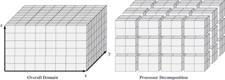
We discretize the domain into a uniform grid of dimensions , such that we have a three-dimensional rectangular cuboid of cell-centered values wherein
This spatial domain is then decomposed in parallel using a standard 3D domain decomposition approach over MPI tasks, with layout , defined automatically via the MPI_Dims_create utility routine, as illustrated in Figure 1. This results in each MPI task “owning” a local grid of dimensions .
Within each cell in the domain we store variables, corresponding to the values of at that spatial location. Here, we employ the newly-introduced N_Vector_MPIManyVector implementation, that allows creation of a single N_Vector out of any valid set of subsidiary N_Vector objects. To this end, we store each of the five fluid fields (, , , and ) in its own N_Vector_Parallel object to simplify access and I/O. We then store all chemical species owned by each MPI task in a single N_Vector_Serial object (note: this will eventually be changed to use a device-specific N_Vector object, such as N_Vector_CUDA, N_Vector_RAJA, or N_Vector_OpenMPDEV). Each MPI task then combines its pointers for the five fluid vectors, along with its own chemical species vector, into its full “solution” N_Vector_MPIManyVector, , using the N_VNew_MPIManyVector routine. An illustration of this MPIManyVector structure is shown in Figure 2.

The final item to note with regard to the spatial discretization is our approach for approximating the flux divergence shown in equation (1). For this, we apply a 5th-order FD-WENO reconstruction, where we precisely follow the algorithm laid out in the seminal paper by Shu [13], which we briefly summarize here. In order to properly conserve mass, momentum, and energy in (1), we first compute the fluxes at each of the six faces surrounding the cell , and apply these in a standard conservative fashion, namely
| (8) | ||||
Since the cells and share the same flux value , this results in conservation to full machine precision (modulo boundary conditions, source terms, and reaction processes). The 5th-order FD-WENO scheme is used to construct each of these face-centered flux values. This algorithm computes the flux using a 6-point stencil of solution values , , , , , and , i.e., the 6 “closest” cell centers to the face along the -direction. The stencils are analagous in the and directions. Thus under our three-dimensional domain decomposition approach outlined above, each MPI task must obtain three layers of “ghost” cells from each of its six neighboring subdomains.
We thus compute the flux divergence using the following steps:
-
1.
Begin exchange of boundary layers with neighbors via asynchronous MPI_Isend and MPI_Irecv calls.
-
2.
Compute and store the fluxes at each face in the strict interior of the subdomain, i.e., for all cell faces whose 6-point stencil involves no data from neighboring MPI tasks. For example, we compute over the ranges . Since the vast majority of computational effort in this portion of the algorithm lies within the arithmetically intense FD-WENO reconstruction itself, we first copy the local stencil of unknowns from their various N_Vector locations into a contiguous buffer before performing the FD-WENO reconstruction at each face.
-
3.
Wait for completion of all asynchronous MPI_Isend and MPI_Irecv calls.
-
4.
Compute the face-centered fluxes near subdomain boundaries, i.e., those face-valued fluxes that were omitted above. As these stencils now depend on values from neighboring subdomains, the only difference from step 2 is that this must use a different routine to copy the local stencil into the contiguous buffer, since these copies must appropriately handle data from the MPI_Irecv buffers.
-
5.
Finally, compute the formula (8) over the entire local subdomain, i.e., for each location over the ranges , , and .
We note that due to the high arithmetic intensity of the FD-WENO approach, each MPI task need not own a very large computational subdomain for the point-to-point communication to be completely overlaid by computation in step 2.
3.2 Temporal discretization
After spatial semi-discretization, the original PDE system (1) may be written as an ODE initial-value problem,
| (9) |
where contains the spatial semi-discretization of the solution vector , contains the spatial semi-discretization of the terms and contains the spatial semi-discretization of the term . Here, we use the “” superscript to denote the “slow” dynamical processes (advection and externally-applied forces), and “” to denote the “fast” reaction processes.
For non-reactive flows in which , the initial value problem is nonstiff, and is therefore solved using a temporally-adaptive explicit Runge–Kutta method from ARKode’s ARKStep module. While that use case is supported by our demonstration code, we do not examine this “single physics” use case here.
For problems involving chemical reactions, the multiphysics initial-value problem (9) typically exhibits multiple temporal scales. We therefore solve these problems using ARKode’s MRIStep module, that employs a third-order accurate multirate infinitesimal step method for problems characterized by two time scales [10, 11, 12]. Here, a single time step to evolve , denoted by , for the full initial-value problem (9), proceeds according to the following algorithm:
-
1.
set ,
-
2.
for :
-
(a)
define the “fast” initial condition: ,
-
(b)
compute the forcing term
-
(c)
for , solve the “fast” initial-value problem
(10) -
(d)
set the new “slow” stage: ,
-
(a)
-
3.
set the time-evolved solution: ,
where correspond to the coefficients for an explicit, -stage “slow” Runge–Kutta method, is padded with a final row, , and where for correspond to the “slow” stage times. In this demonstration application, we use the default “KW3” MRIStep slow Runge–Kutta coefficients [6]. For evolution of the “fast” problems (10) above, we use a temporally-adaptive, diagonally-implicit Runge–Kutta method from ARKode’s ARKStep module, namely the “ARK437L2SA” DIRK method from [5].
As we will describe in Section 4 below when discussing our physical test problem, chemically-reactive flows exhibit fast transient behavior, so their stable evolution heavily depends on the inherent robustness of temporally-adaptive integration. However, the primary purpose of this report is to document parallel performance of the MPIManyVector and other algebraic solver enhancements that have been recently added to SUNDIALS. As such, we employ a hybrid adaptive + fixed-step integration approach for the fast time-scale subproblems (10). Specifically, we partition the overall temporal domain into two parts, and . The first portion is considered the “transient” time period, where chemical species exhibit very fast dynamical changes, as they rapidly adjust from their initial conditions to their slower (but still fast) solution trajectories. This time period is therefore evolved with ARKStep’s temporal adaptivity enabled; the adaptivity parameters employed for this phase of the simulations are provided in Table 1.
| Parameter | Value |
|---|---|
| ARKStepSetAdaptivityMethod | |
| ARKStepSetMaxNumSteps | 5000 |
| ARKStepSetSafetyFactor | 0.99 |
| ARKStepSetErrorBias | 2.0 |
| ARKStepSetMaxGrowth | 2.0 |
| ARKStepSetMaxNonlinIters | 10 |
| ARKStepSetNonlinConvCoef | 0.01 |
| ARKStepSetMaxStep1 | |
| Relative tolerance | |
| Absolute tolerance |
The second (and typically much longer) time interval, , is evolved using a fixed “fast” time step size, , thereby bypassing ARKStep’s built-in temporal adaptivity approaches to produce a more predictable amount of work as the problem is pushed to larger scales. The challenge with using fixed time step sizes in such an application is that in fixed-step mode, any algebraic solver convergence failure becomes fatal, and causes the entire simulation to halt. Thus, the value of must be chosen appropriately, to balance the need for adaptivity-based robustness during initial transient chemical evolution (i.e., larger ) against the desire for a fixed amount of computational work per MPI task when performing weak scaling studies (i.e., smaller ). We present the values used in the current studies in Section 4, when discussing the particular test problem used here.
Both evolution periods, and , are evolved using single calls to MRIStepEvolve, although the second period can be broken into a sequence of separate subperiods so that solution statistics can be displayed, and/or solution checkpoint files can be written to disk. However, since this study focuses on overall solver performance, all such diagnostic and solution output is disabled.
3.3 Algebraic solvers
Since the slow time scale is currently treated explicitly, the only algebraic solvers present in these calculations occur when evolving each “fast” subproblem (10). As these subproblems are evolved using diagonally implicit Runge–Kutta (DIRK) methods, each stage may require the solution of a nonlinear algebraic system of equations. We briefly outline the structure of these DIRK methods, and then discuss the algebraic solvers used for these problems.
Considering the fast IVP
a -stage DIRK method with coefficients evolves one time step , denoted for short by , via the algorithm:
-
1.
for , solve for the “stages” that satisfy the equations
(11) where ,
-
2.
compute the time-evolved solution
-
3.
(optional) compute the embedded solution
The solution of at most nonlinear algebraic systems (11) is required to compute each stage . Writing these systems in standard root-finding form, for each fast substep we must solve separate nonlinear algebraic systems:
| (12) |
where the first bracketed term contains the implicit portions of the nonlinear residual, and the second bracketed term contains known data. We note that each can be a very large vector. However since , and is just the spatially semi-discretized version of the reaction function , we see that although equation (12) is nonlinear, it only involves couplings between unknowns that are co-located at each spatial location, . Thus we may instead consider equation (12) to be equivalent to a system of separate nonlinear systems of equations, each coupling only unknowns.
We may therefore leverage this structure in a myriad of ways to improve parallel performance. At one extreme, we may break apart the large nonlinear system (12) into separate nonlinear systems, performing an independent Newton iteration separately at each spatial location. At a coarser level, we could instead break apart equation (12) into separate nonlinear systems, one per MPI task, so that each Newton iteration may proceed without parallel communication. The relative merits of these choices (as well as intermediate options, e.g., breaking this into two-dimensional “slabs” or one-dimensional “pencils” of spatial cells) is not investigated here, but may be pursued in future efforts. In this work, we utilize an even coarser approach that solves the full nonlinear system of equations (12) using a single modified Newton iteration (the ARKStep default), that couples all unknowns across the entire parallel machine. However, we exploit the problem structure by providing a custom linear solver module that solves each MPI task-local linear system independently. Due to the structure of , the Jacobian matrix is block-diagonal,
where each MPI task-local block , is itself block-diagonal,
with each cell-local block . We leverage the extreme sparsity of these MPI task-local Jacobian matrices by constructing each matrix in compressed-sparse-row (CSR) format, and storing them using standard SUNSparseMatrix objects. These are thus automatically converted to Newton system matrices within ARKStep’s generic direct linear solver interface. We then leverage the block-diagonal structure and solve the overall Newton linear systems using the SUNLinSol_KLU linear solver module separately on each MPI task.
As this is an optimally-parallel direct linear solver for the block-diagonal Newton linear systems, and since itself involves no parallel communication, the only “wasted” MPI communication that occurs in our solution of each nonlinear algebraic system (12) is the computation of residual norms to determine completion of the Newton iteration. In future studies we plan to supply a custom nonlinear solver that will remove this extraneous communication. We also plan to explore alternate strategies that will further leverage the block-diagonal structure (slabs, pencils, etc.), particularly once we transition simulation of the chemical kinetics to GPU accelerators.
4 Test Description
In this work, we consider the test problem of an advecting and reacting primordial gas. In addition to the five “standard” fluid variables described in Section 2, we evolve 10 chemical species (i.e., ), for a total of 15 variables per spatial location. These species model the chemical behavior of a low density primordial gas, present in models of the early universe [1, 3, 8, 15]. This model consists of the species:
-
•
– neutral atomic Hydrogen density
-
•
– positively-ionized atomic Hydrogen density
-
•
– negatively-ionized atomic Hydrogen density
-
•
– neutral molecular Hydrogen density
-
•
– ionized molecular Hydrogen density
-
•
– neutral atomic Helium density
-
•
– partially-ionized atomic Helium density
-
•
– fully-ionized atomic Helium density
-
•
– free electron density
-
•
– internal gas energy (proportional to temperature)
The full set of chemical rate equations that encode these reactions comprise the reaction term, , used in our code. Both the routine to evaluate this “right-hand side” function, as well as a corresponding routine to evaluate its Jacobian in CSR format, are provided by the Dengo software package [16], a source-code generation utility that translates from astropysical chemical rate equations to C (or CUDA) code that, among other things, implements these routines and generates the corresponding reaction rate lookup tables in HDF5 format [7].
We highlight the fact that the internal gas energy, , may be uniquely defined by the fluid fields, since
and thus this reaction network only adds 9 new independent fields to the simulation. However, due to the multirate solver structure described in Section 3.2, wherein control over the simulation cleanly shifts between “slow” and “fast” phases, we use both and to store the “current” gas/total energy value. Furthermore, by storing two versions of the energy we may use our preferred N_Vector data structure layout – five N_Vector_Parallel objects for the fluid fields, plus one MPI task-local N_Vector for the chemistry fields. We further note that this structure will enable follow-on efforts in which the entire chemical network (data and computation) are moved to GPU accelerators, through merely swapping out our N_Vector_Serial object and enabling Dengo’s generation of GPU-enabled source code.
We initialize these simulations using a “clumpy” density field. Here, the overall density field at any point is given by the formula
| (13) |
where g / cm3 is the background density, is the total number of MPI tasks in the simulation (i.e., the number of “clumps” is proportional to the number of MPI tasks), and is the location of the center of the computational domain. We choose the remaining parameters from uniform random distributions in the following intervals:
-
•
, i.e, each clump is centered randomly within the domain,
-
•
is the clump “radius,” i.e., each clump extends anywhere from 3 to 6 grid cells away from its center, and
-
•
is the clump “size,” i.e., each clump has density up to 5 times larger than the background density.
The simulation begins with a near-uniform temperature field, with only a single higher-temperature region located in the clump at the domain center:
| (14) |
where the background temperature is chosen to be K.
The chemical fields are initialized to values proportional to the overall density, with:
| (15) | ||||
| (16) | ||||
| (17) | ||||
| (18) | ||||
| (19) | ||||
| (20) | ||||
| (21) | ||||
| (22) | ||||
| (23) | ||||
| (24) |
where is Boltzmann’s constant, is the ratio of specific heats, and the gas number density is given by
| (25) | ||||
| (26) |
Finally, we assume that the gas is initially static (i.e., ), and that no external forces are applied (i.e., ).
We perform the simulations on the spatial domain , and enforce reflecting boundary conditions over . Our base grid simulations (discussed below) are computed over the temporal domain .
Since the Dengo-supplied chemical network expects values in CGS units, but our FD-WENO solver prefers dimensionless quantities, we non-dimensionalize by using the scaling factors:
-
•
MassUnits = ,
-
•
LengthUnits = , and
-
•
TimeUnits = ,
that correspond to the variable scaling factors
-
•
DensityUnits = ,
-
•
MomentumUnits = , and
-
•
EnergyUnits = ,
which we use to convert between “dimensional” and “dimensionless” values as control is passed back-and-forth between fluid and chemistry solvers. Furthermore, we note that these choices of LengthUnits and TimeUnits result in the normalized space-time domain – all discussion of time step sizes or the temporal domain in the remainder of this report refer to these quantities in dimensionless units.
As is typical for large-scale explicit simulations, we perform weak scaling studies by examining the time required per slow step. Thus as we refine the spatial discretization (e.g., ) and thus reduce the slow step size (e.g., ), we shorten the overall time interval for each simulation (e.g., ), thereby guaranteeing a steady number of “slow” time steps. However, since the fast time scale calculations are performed implicitly and thus have no resolution-based CFL stability restriction, we may choose between two alternate options:
-
(a)
maintain an essentially-constant fast step size (i.e., ), as would likely occur for chemical accuracy considerations alone,
-
(b)
refine the fast step size in proportion to the slow step size (i.e., ), resulting in an essentially constant amount of work per MPI task per slow time step as the mesh is refined.
Since the purpose of this report is to examine the parallel scalability of the MPIManyVector and other general SUNDIALS enhancements, we chose option (b) above, since option (a) would result in a decreasing number of fast time steps per simulation. Thus the ensuing scalability results may be seen as a “worst-case” performance metric for scalability of multirate methods applied to physical problems of similar structure.
We perform a standard explicit method weak scaling study for this problem, wherein we increase the total number of nodes and total problem size proportionately. For each spatial mesh, we decrease the “slow” step size to maintain a constant CFL stability factor (i.e., ). In each simulation, the initial “transient” phase runs over the time interval , and the “fixed-step” phase runs for the remainder of the time interval. We set a value to maintain a constant timescale separation ratio ; for the transient phase this is the maximum step size for the temporal adaptivity approach; then becomes the fixed step size for the latter portion of the calculation. As stated above, we maintain an essentially-constant computational effort per MPI task by shortening the overall simulation time proportionately with . We note that this causes the relative fraction of “fixed-step” versus “transient” portions of the simulation to decrease at larger scales. However, since we use the same value for the fixed-step phase of the calculation as we use for the maximum allowed transient time step size, then as the spatial mesh is refined we find that an increasing fraction of transient chemical time steps use this maximum value, thereby providing a robust solution approach that in the limit achieves a fixed amount of work per MPI task as the mesh is refined. In Table 2 we provide a summary of these parameters for each problem size tested.
| Nodes | Spatial Mesh | Total Unknowns | Slow step | Fast step | Final time |
|---|---|---|---|---|---|
| 2 | |||||
| 16 | |||||
| 128 | |||||
| 432 | |||||
| 1024 | |||||
| 2000 | |||||
| 3456 |
For each spatial mesh size, we performed two simulations. The first used two “newer” features added to the SUNDIALS N_Vector API:
-
•
Fused vector operations – for back-to-back N_Vector operations that are performed in SUNDIALS’ various solvers, we created a set of new N_Vector kernels that perform this multiple combination of operations per memory access, thereby increasing arithmetic intensity and reducing the number of function calls (or GPU kernel launches).
-
•
Local reduction operations – since an MPIManyVector is merely a vector that is comprised of a subset of other N_Vector objects, any operation requiring an MPI reduction (e.g., dot-product or norm) would naively result in multiple separate MPI_Allreduce calls. We therefore created a set of new N_Vector routines that only perform the MPI task-local portion of these operations, waiting to call MPI_Allreduce until the overall accumulated quantity is available, and thereby reducing MPI latency effects.
The second simulation performed at each spatial mesh size was run with these newer features disabled, so that we could assess the benefits of these newer features “at scale.”
5 Performance Results
For each simulation we manually instrumented the code with profiling timers based on MPI_Wtime for a variety of logical subsets of the code:
-
(a)
Setup – this includes construction of MRIStep, ARKStep, and Dengo data structures, as well as construction of initial condition values. We note that due to the sum over clumps in creation of the initial density field (13), this component should exhibit slowdown as the problem size is increased. We therefore do not include this contribution when assessing the overall parallel efficiency.
-
(b)
I/O – this includes all time spent in output of diagnostic information to stdout and stderr as the simulation proceeds, as well as all time spent in reading and writing HDF5 files. For the results that follow, most of these capabilities were disabled so that disk I/O would not affect our performance measurements.
-
(c)
MPI – this includes all time spent in parallel communication by this demonstration application code. This does not include the MPI time spent in SUNDIALS’ N_Vector operations (e.g., dot-products and norms).
-
(d)
Packing – this includes all time spent in packing the contiguous memory buffers (see steps 2 and 4 from Section 3.1) that are used in the FD-WENO flux reconstruction.
-
(e)
FD-WENO – this includes all time spent in performing the FD-WENO flux reconstruction.
- (f)
-
(g)
fslow – this includes the time spent in (f) above, as well as all translation when converting between dimensional and dimensionless units for the fluid and chemical fields.
-
(h)
ffast – this includes only the time spent in evaluating the ODE right-hand side for the Dengo-supplied chemical network.
-
(i)
JFast – this includes only the time spent in evaulating the Jacobian of ffast, and storing those values in CSR matrix format.
-
(j)
Linear solver setup – this includes all time spent by our custom SUNLinearSolver implementation to factor its block-diagonal linear system matrices; this is essentially just the time spent in MPI task-local calls to the SUNLinSol_KLU “Setup” routine.
-
(k)
Linear solver solve – this includes all time spent by our custom SUNLinearSolver implementation to solve its block-diagonal linear systems; it is essentially just the time spent in MPI task-local calls to the SUNLinSol_KLU “Solve” routine.
-
(l)
Overall “transient” simulation time – this includes all time spent in evolving the solution over the initial transient time interval, . We note that this does not include the “Setup” time (a) above.
-
(m)
Overall “fixed-step” simulation time – this includes all time spent in evolving the solution over the second fixed-fast-step time interval, .
-
(n)
Total simulation time – this includes both the “transient” and “fixed-step” simulation times, as well as the “Setup” time for the simulation, i.e., .
We note that although these profilers only directly measure the time spent in the “multiphysics” portions of this simulation, we may indirectly measure the overall amount of time spent in SUNDIALS modules (MRIStep, ARKStep, N_Vector, etc.) by subtracting the amount of time spent in right-hand side, Jacobian, and linear solver operations from the overall amount of time spent in evolving the system, i.e.,
We further note that the vast majority of synchronization points in this code occur in N_Vector reduction operations (e.g., dot-products and norms), and thus the “SUNDIALS time” includes all such synchronization points. While some local synchronization occurs from nearest-neighbor communication for flux calculations, this is overlaid by flux computations over subdomain interiors, and is directly measured by the timers (c), (f), and (g) above.
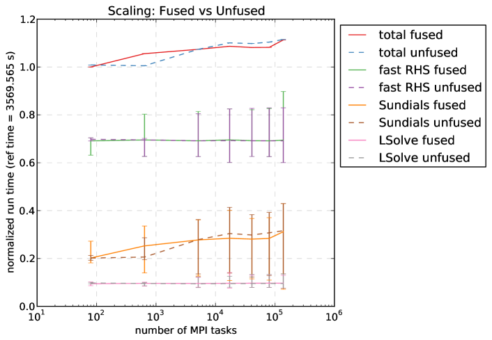
We provide weak-scaling results with these timers in Figure 3. While we collected data on a large number of code components, most of those timers required only trace amounts (less than 0.5%) of the total runtime: Setup, I/O, MPI, Packing, FD-WENO, Euler, fslow, Jfast, and linear solver setup. We have thus removed these measurements from this figure to focus on the time-intensive aspects of the code, as well as their parallel scalability. Since each profiler resulted in slightly different times on each MPI task, for each curve we plot both the mean task time, as well as error-bars showing the minimum and maximum reported values. However, since the ‘Sundials’ times are only measured indirectly, these minimum and maximum values may be exaggerated since they incorporate the variability from other portions of the code (in addition to variability resulting from within SUNDIALS itself). Thus the error bars for the ‘Sundials’ curve in this Figure likely over-estimate the variability encountered by MPI tasks in the SUNDIALS infrastructure.
Additionally, in Table 3 we provide the parallel efficiency of each simulation, in comparison with the 80-task “fused” simulation.
| MPI tasks | |||||||
|---|---|---|---|---|---|---|---|
| 80 | 640 | 5,120 | 17,280 | 40,960 | 80,000 | 138,240 | |
| Fused | 1.00 | 0.95 | 0.93 | 0.92 | 0.92 | 0.92 | 0.90 |
| Unfused | 0.99 | 0.99 | 0.93 | 0.91 | 0.91 | 0.90 | 0.90 |
We first note that at the smallest scale tested ( grid with 80 MPI tasks), the fast chemical right-hand side routine accounted for almost 70% of the total runtime, followed by general SUNDIALS infrastructure (slightly over 20%), and linear system solves (slightly under 10%). Furthermore, of these the fast chemical right-hand side routine and linear solver times showed perfect weak scalability, while the time spent in SUNDIALS infrastructure increased by almost 42%, leading to run-time increase of about 11% for the overall simulation code (i.e., approximately 90% parallel efficiency compared to the smallest test). We additionally note that the variance in reported times increased at larger scales, particularly for the SUNDIALS infrastructure, that showed up to 77% variance at 138,240 MPI tasks. Interestingly, the various MPI tasks showed essentially zero variability in the total simulation times reported. This is likely due to the fact that these “total simulation” timers surrounded calls to MRIStepEvolve; since the last thing this does before returning is compute an error norm (via MPI_Allreduce), it effectively synchronizes all MPI tasks just prior to stopping the timer. Finally, we note that the “fused” and “unfused” versions showed no statistically-significant differences.
6 Conclusions
While we expected the general strong performance results shown in Section 5, some of these came as more of a surprise than others.
From an application viewpoint, we note that our approach for interleaving communication and computation for the advective fluxes proved sufficient, with all directly-measured “MPI” timings remaining at essentially zero for all scales tested. Moreover, due to the multirate structure of this application problem and testing setup, the advective portion of the right-hand side was essentially “free” in comparison to the chemical kinetics that dominated the simulation time.
From a SUNDIALS-infrastructure viewpoint, we posit that the slowdown shown in the SUNDIALS infrastructure was entirely due to synchronization-induced latency in MPI_Allreduce calls. This conclusion is based on two observations. First, while the “fused” version reduced the number of these calls by 80%, it left the frequency of these synchronization points essentially unchanged, and thus the near-identical runtimes for both indicate that the additional MPI_Allreduce calls in the “unfused” version do not increase the overall global synchronization of the code. Moreover, the large variance reported for SUNDIALS infrastructure among MPI tasks indicates that some tasks spent considerably more time waiting at these synchronization points than others. However, since we could only indirectly measure the time spent in SUNDIALS routines, this variance may be exaggerated.
Based on the above, we anticipate that this code will tremendously benefit from three planned investigations. First, we plan to extend this implementation to construct a custom SUNNonlinearSolver for the fast time scale. As discussed in Section 3.3, this can be constructed to remove all MPI_Allreduce calls at the algebraic solver level, in turn reducing over 98% of the overall MPI_Allreduce calls from the “fast” time scale (for the 138,240 MPI task run, there were 61,195 Newton iterations and 1,007 fast time steps; ), thereby effectively removing nearly all global synchronization from these simulations.
Second, we plan to port the chemical network data, the fast right-hand side computations, the fast Jacobian construction routine, and the fast-time scale algebraic solvers to GPU accelerators. We note that even at the largest scales tested here ( grid on 138,240 MPI tasks), evolution of these arithmetically-intense “fast” chemical processes required over 70% of the total runtime (fast RHS + lsolve). Moreover, the types of calculations performed in this module should be amenable to GPU architectures, and thus their conversion could likely result in significant performance improvements over the results shown here.
Third, instead of requiring application codes to only indirectly measure the time spent in SUNDIALS, and thus lumping all of SUNDIALS’ various actions (plus any unmeasured work) into a single performance metric, future performance studies with SUNDIALS would benefit tremendously from direct measurements of SUNDIALS performance, notably if these measurements were broken apart into logical units (e.g., vector reductions, vector arithmetic, integrator infrastructure, nonlinear solvers, linear solvers, preconditioners, etc.). We are thus investigating inclusion of direct measurements of SUNDIALS performance through a tool such as Caliper [2]. Additionally, such tools could track more than just runtime, enabling measurement of system-level counters.
Acknowledgements
This research was supported by the Exascale Computing Project (ECP), Project Number: 17-SC-20-SC, a collaborative effort of two DOE organizations – the Office of Science and the National Nuclear Security Administration, responsible for the planning and preparation of a capable exascale ecosystem, including software, applications, hardware, advanced system engineering and early testbed platforms, to support the nation’s exascale computing imperative.
Support for this work was also provided through the Scientific Discovery through Advanced Computing (SciDAC) project “Frameworks, Algorithms and Scalable Technologies for Mathematics (FASTMath),” funded by the U.S. Department of Energy Office of Advanced Scientific Computing Research and National Nuclear Security Administration.
This research used resources of the Oak Ridge Leadership Computing Facility, which is a DOE Office of Science User Facility supported under Contract DE-AC05- 00OR22725.
This work work was performed under the auspices of the U.S. Department of Energy by Lawrence Livermore National Laboratory under contract DE-AC52-07NA27344. Lawrence Livermore National Security, LLC. LLNL-TR-791538.
This document was prepared as an account of work sponsored by an agency of the United States government. Neither the United States government nor Lawrence Livermore National Security, LLC, nor any of their employees makes any warranty, expressed or implied, or assumes any legal liability or responsibility for the accuracy, completeness, or usefulness of any information, apparatus, product, or process disclosed, or represents that its use would not infringe privately owned rights. Reference herein to any specific commercial product, process, or service by trade name, trademark, manufacturer, or otherwise does not necessarily constitute or imply its endorsement, recommendation, or favoring by the United States government or Lawrence Livermore National Security, LLC. The views and opinions of authors expressed herein do not necessarily state or reflect those of the United States government or Lawrence Livermore National Security, LLC, and shall not be used for advertising or product endorsement purposes.
References
- [1] T. Abel, P. Anninos, Y. Zhang, and M. L. Norman, Modeling primordial gas in numerical cosmology, New Astronomy, 2 (1997), pp. 181 – 207.
- [2] D. Boehme, Caliper: Application introspection system. https://computing.llnl.gov/projects/caliper, 2019.
- [3] S. C. O. Glover and T. Abel, Uncertainties in H2 and HD chemistry and cooling and their role in early structure formation, Monthly Notices of the Royal Astronomical Society, 388 (2008), pp. 1627–1651.
- [4] A. C. Hindmarsh, P. N. Brown, K. E. Grant, S. L. Lee, R. Serban, D. E. Shumaker, and C. S. Woodward, Sundials: Suite of nonlinear and differential/algebraic equation solvers, ACM Transactions on Mathematical Software (TOMS), 31 (2005), pp. 363–396.
- [5] C. A. Kennedy and M. H. Carpenter, High-order additive Runge–Kutta schemes for ordinary differential equations, Applied Numerical Mathematics, 136 (2019), pp. 183–205.
- [6] O. Knoth and R. Wolke, Implicit-explicit Runge-Kutta methods for computing atmospheric reactive flows, Applied Numerical Mathematics, 28 (1998), pp. 327–341.
- [7] Q. Koziol and D. Robinson, HDF5. https://doi.org/10.11578/dc.20180330.1, March 2018.
- [8] H. Kreckel, H. Bruhns, M. Čížek, S. C. O. Glover, K. A. Miller, X. Urbain, and D. W. Savin, Experimental results for h2 formation from h- and h and implications for first star formation, Science, 329 (2010), pp. 69–71.
- [9] Oak Ridge Leadership Computing Facility, Summit. https://www.olcf.ornl.gov/summit, 2019.
- [10] M. Schlegel, O. Knoth, M. Arnold, and R. Wolke, Multirate Runge-Kutta schemes for advection equations, Journal of Computational and Applied Mathematics, 226 (2009), pp. 345–357.
- [11] M. Schlegel, O. Knoth, M. Arnold, and R. Wolke, Implementation of multirate time integration methods for air pollution modelling, Geoscientific Model Development, 5 (2012), pp. 1395–1405.
- [12] M. Schlegel, O. Knoth, M. Arnold, and R. Wolke, Numerical solution of multiscale problems in atmospheric modeling, Applied Numerical Mathematics, 62 (2012), pp. 1531–1543.
- [13] C.-W. Shu, High-order finite difference and finite volume WENO schemes and discontinuous Galerkin methods for CFD, International Journal of Computational Fluid Dynamics, 17 (2003), pp. 107–118.
- [14] SUNDIALS: Suite of nonlinear and differential/algebraic equation solvers, SUNDIALS Web page. https://computing.llnl.gov/projects/sundials, 2019.
- [15] C. S. Trevisan and J. Tennyson, Calculated rates for the electron impact dissociation of molecular hydrogen, deuterium and tritium, Plasma Physics and Controlled Fusion, 44 (2002), pp. 1263–1276.
- [16] M. Turk, D. Silvia, and K. S. Tang, Dengo – a meta-solver for chemical reaction networks and cooling processes. https://github.com/hisunnytang/dengo-merge, 2019.