Gear Junctions between Chiral Boron Nitride Nanotubes
Abstract
A gear effect is demonstrated at parallel and cross junctions between boron nitride nanotubes (BNNTs) via atomistic simulations. The atoms of neighboring BNNTs are meshed together at the junctions like gear teeth through long-range non-covalent interaction, which are shown to be able to transmit motion and power. The sliding motion of a BNNT can be spontaneously translated to rotating motion of an adjoining one or viceversa at a well-defined speed ratio. The transmittable motion and force strongly depend on the helical lattice structure of BNNTs represented by a chiral angle. The motion transmission efficiency of the parallel junctions increases up to a maximum for certain BNNTs depending on displacement rates. It then decreases with increasing chiral angles. For cross junctions, the angular motion transmission ratio increases with decreasing chiral angles of the driven BNNTs, while the translational one exhibits the opposite trend.
I Introduction
Gears are key components in most machines and devices with moving parts. The earliest example of gear dates from the 4th century BC, and is preserved at the Luoyang Museum in China.Needham (1965) Gears are considered to be not only one of the greatest inventions of all time, but also essential for future nanotechnology. Top-down design has emerged as a major methodology for inventing nano-machines such as molecular analogues of cars,Rapenne and Joachim (2017) motors,Kassem et al. (2017) elevators,Badjic et al. (2004) shuttlesBrouwer et al. (2001), and so forth. However, the lack of an effective motion transmission system remains a critical problem for the top-down design of nano-machines inspired by their macroscopic-world counterparts. Difficulties include implementing well-positioned meshing teeth on nanostructures,Pantarotto et al. (2008) as well as strong friction and adhesion due to the extreme surface-to-volume ratio of nanomaterials.Kim et al. (2007) To this end, we present an idea to use the long-range interaction between atoms as meshing gear teeth for transmitting power, taking boron nitride nanotube (BNNTs) junctions as examples.
BNNTs are promising building blocks of nanoscale devices and machines owing to their peculiar structure, superior mechanical strength, high thermal conductivity and chemical stability.Zhang et al. (2017); Arenal et al. (2010) A single-walled BNNT consists of a single layer of B and N atoms arranged in a hexagonal h-BN lattice. The layer can be rolled up in different directions with respect to the central axis of the BNNT leading to different chiralities, just like in carbon nanotubes (CNTs).Golberg et al. (2010) At the junctions between two BNNTs, the tubes are held together by both van der Waals (vdW) and electrostatic forces. These forces depend on the relative crystalline orientations of the tubes,Wang (2019) i.e., on the local stacking of layers.Marom et al. (2010) Indeed, non-covalent interactions between CNTs and substrates have long been known to strongly depend on the interfacial stacking sequence.Kolmogorov et al. (2004); Falvo et al. (2000); Chen et al. (2013); Sinclair et al. (2018) Based on this feature, screw-like motions have recently been reported for walls in concentric CNTs.Guerra et al. (2017); Cai et al. (2014) Barreiro et al. observed directional motion of a gold nanoparticle on a CNT in scanning electron microscopy experiments.Barreiro et al. (2008)
BNNTs can be expected to present similar dependences on the stacking sequence owing to their crystalline similarity to CNTs. However, the optimal stacking sequences of successive h-BN sheets is known to be different from those of graphene sheets.Gilbert et al. (2019); Wang (2018) Moreover, the non-covalent force between BNNTs is much stronger than that between CNTs due to interlayer electrostatic interaction.Falin et al. (2017) Recently, ultrahigh friction has been measured between shells of multi-walled BNNTs in atomic force microscopy experiments.Nigues et al. (2014) To explore gear effects at the interface between h-BN layers based on possible stacking sequence features, we conduct molecular mechanics simulations of non-covalent junctions between chiral single-walled BNNTs. Two different types of junctions are considered here: a parallel junction between two aligned BNNTs and a cross junction between two perpendicular ones.
II Methods
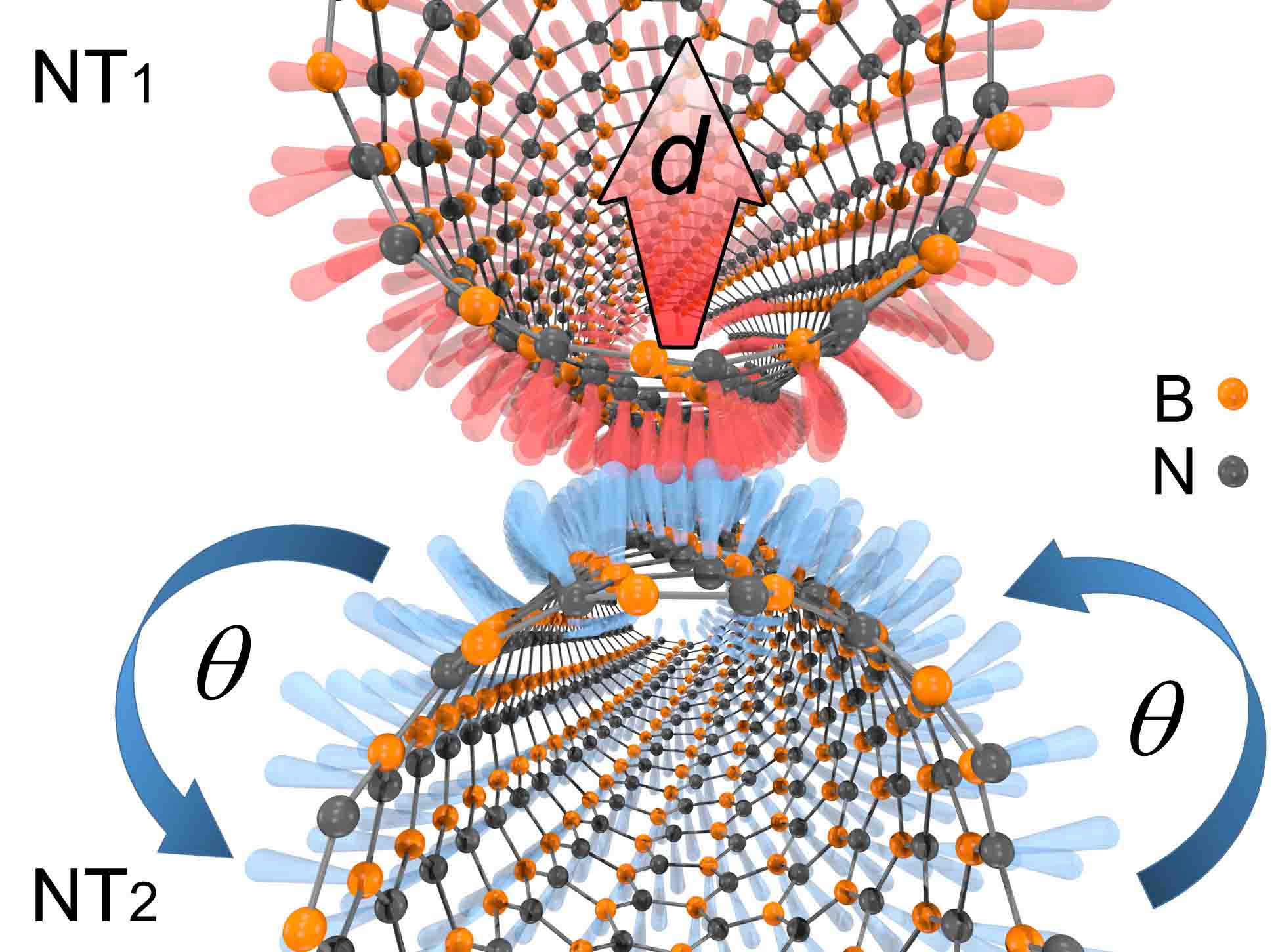
A wall of a BNNT can be described as a h-BN sheet rolled up at a specific angle , and thus characterized by a pair of integers and defining a vector in the h-BN lattice.Arenal et al. (2010); Golberg et al. (2010); Zeng et al. (2010) This vector forms a circumference when the h-BN sheet is rolled up to create a BNNT. The tube radius and the chiral angle are well-defined functions of and , namely
| (1) |
where is the lattice constant. varies between and , covering the spectrum from zigzag to armchair BNNTs. A driving tube (denoted as NT1) is first caused to slide along its axis, while the other, NT2, can freely move in the plane normal to its axis, and its response to the displacement of NT1 is simulated by a molecular mechanics procedure in which the equilibrium atomistic configuration of the atoms is computed at each iteration by minimizing the total potential energy of the system.Wang and Philippe (2009); Wang (2009); Wang et al. (2010, 2007); Wang and Devel (2007) The simulation scheme is also illustrated in an animation provided as part of the Supporting Information.
The potential energy of the system is given by the sum of those of covalent bonding (cov), long-rang van der Waals (vdW), and electrostatic (elec) interactions,
| (2) |
where and are the total number of atoms in the NT1 and NT2, respectively. is given by the three-body Tersoff potential,Tersoff (1988)
| (3) |
where and denote the interatomic repulsion and attraction terms between the valence electrons, respectively. is a scale factor depending on the interatomic distance . The many-body effects are included in the bond-order function , which depends on the interatomic distance, the bond angle, the dihedral angle and the bond conjugation. More details including the parameterization and benchmarks for this potential is provided elsewhere.Los et al. (2017); Tang et al. (2011)
The inter-tube electrostatic potential is calculated by a pairwise Coulombic function
| (4) |
where is the Coulomb’s constant, and as the effective partial charges for B and N atoms, respectively.
The Lennard-Jones (LJ) force field is employed to describe ,Thamwattana and Hill (2007)
| (5) |
with potential well depths of , and and equilibrium distances of , and for the B-B, B-N and N-N interactions, respectively. The long-range interaction cutoff radius is set to . The Kolmogorov-Crespi (KC) force field has been reported to provide an improved description to the interaction potential between atomic layers at a high load,Kolmogorov and Crespi (2005) and has recently been parametrized for flat boron nitride sheets.Maaravi et al. (2017) However, minor differences between the KC and LJ models are expected for these simulations, since the BNNTs are placed in vacuum with no external pressure. The inter-tube force should therefore mainly depend on the positions of the potential peaks, while the depth of the potential well should have a far weaker effect.Reguzzoni et al. (2012) Moreover, the use of the constant effective ionic charges is expected to hold as a reasonable approximation for our periodic system according to a comparison made by Maaravi et al. Maaravi et al. (2017). Note that we consider junctions between free-standing BNNTs without significant deformation of those adsorbed in a substrate.Zhao et al. (2014); Qi et al. (2018)
III Results and Discussion
III.1 Parallel Junctions
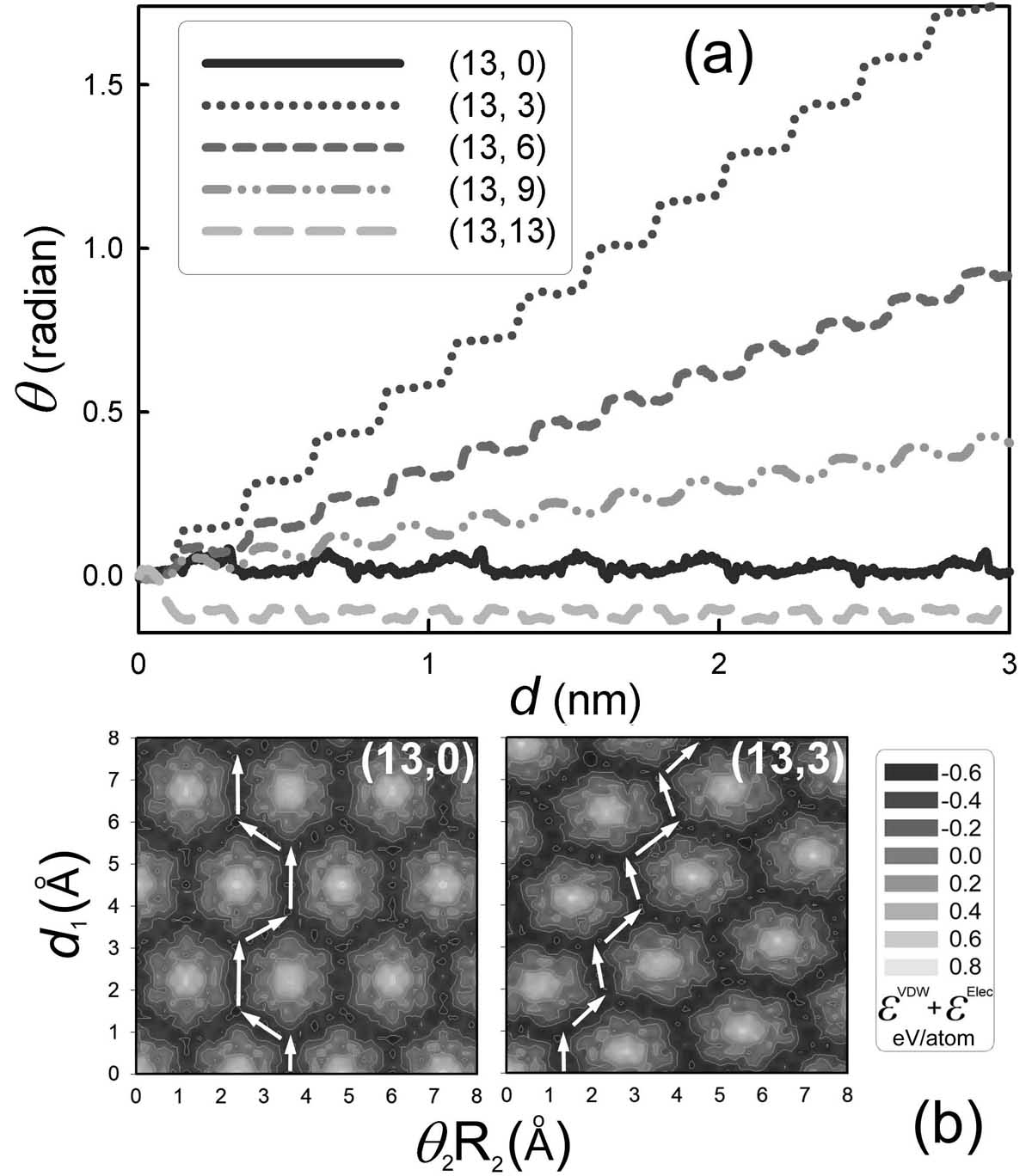
We first consider a simple case of a parallel junction between two identical infinite BNNTs aligned side by side. NT2 is observed to rotate around its axis in response to the translational motion of NT1 as shown in Fig. 2(a). On average, the rotation angle of the NT2 increases linearly with increasing displacement of NT1, with a proportionality constant dependent on tube chirality. For instance, NT2 rotates faster for BNNTs with small chiral angles, as seen in the zigzag (13,0) BNNT. However, the zigzag and armchair BNNTs oscillate back and forth instead of rotating continuously. Moreover, all these curves contain oscillations with a certain period, which corresponds to the dimension of a unit cell in the BNNT lattice. This typical oscillation is often measured by scanning probe microscopy experiments,Vilhena et al. (2016); Dienwiebel et al. (2004) and is correlated with the distribution of the potential energy at the interface.
The atoms in a BNNT are arranged in a hexagonal pattern, with their orbitals forming an eggbox-like potential landscape as shown in Fig. 2(b). Therefore, it stands to reason that, when two BNNTs are put in contact, there will be some specific directions in which the BNNTs can slide along each other more easily. Those easy directions are the keys to the chirality dependence of the motion transmission behavior. BNNTs of different chiralities result in different distributions of the potential energy at the surface,Verhoeven et al. (2004) which lead to different energetically optimized paths (EOPs). In Fig. 2(b), the rotation of the NT2 is represented by the abscissas while the sliding of the NT1 is given by the ordinates. It is clear that the shape and periodicity of the EOPs are consistent with those of the corresponding - curves in Fig. 2(a). For instance, following the EOP, the angle of the BNNT oscillates back and forth when NT1 slides (a displacement along the horizontal axis), a behavior in contrast to that of the BNNT. Note that a non-orthogonal EOP in the plane will results in a helical orbit on the BNNT surface similar to that previously reported for a gold nanoparticle inside CNTs.Schoen et al. (2006)
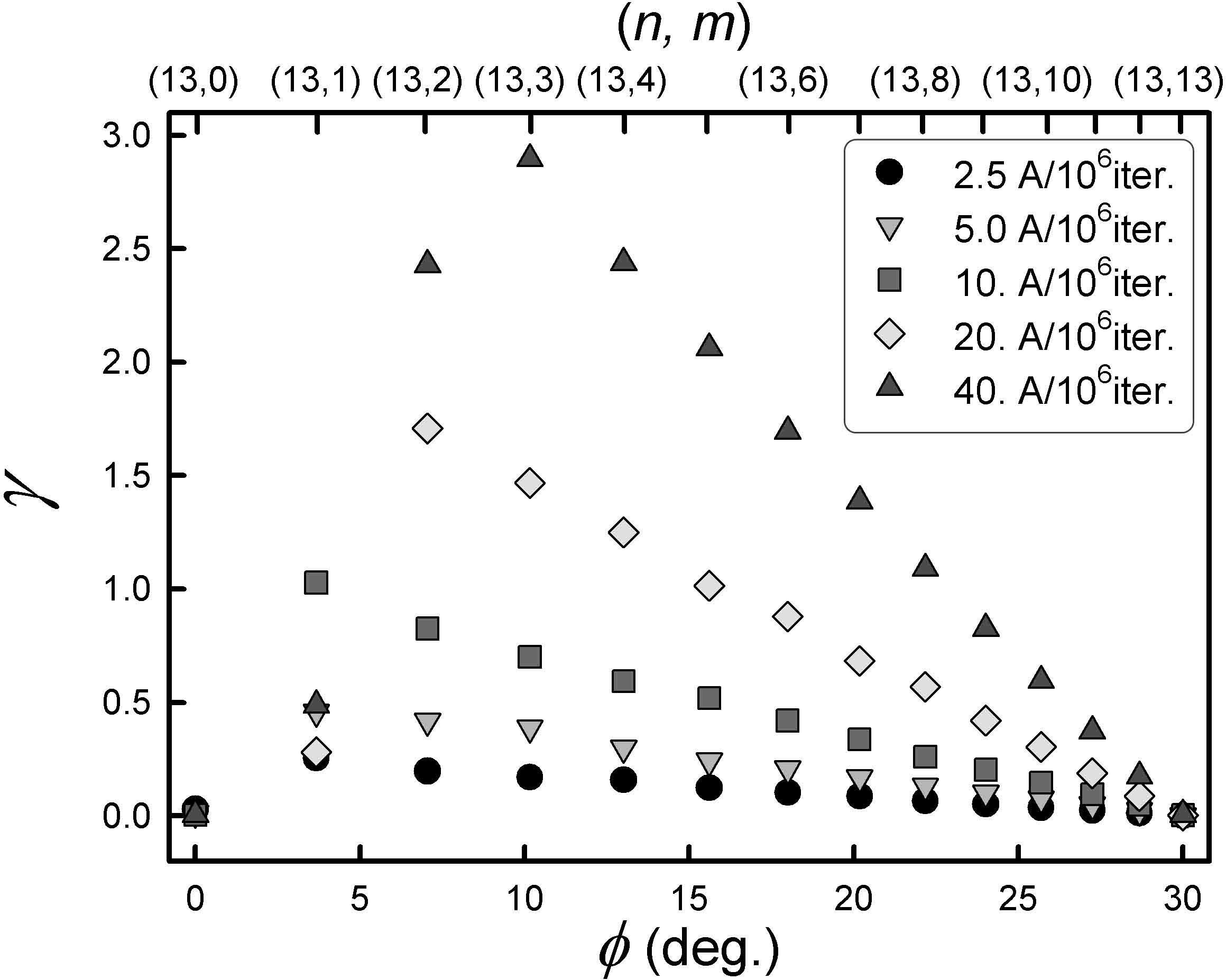
A dimensionless factor proportional to the slope of the - curves in Fig. 2(a) can be defined, to represent the efficiency of motion transmission of the parallel junctions between BNNTs,
| (6) |
where is measured in radians. is plotted as a function of the chiral angle in Fig. 3. It decreases linearly with increasing , while it is almost zero for the zigzag and armchair BNNTs since they oscillate instead of rotating. also increases with increasing sliding rates of NT1. This rate dependence can be understood in terms of the inertia of the minimization procedure at branching points of the potential energy landscape where it has to choose between two energetically degenerate paths [see Fig. 2(b)].
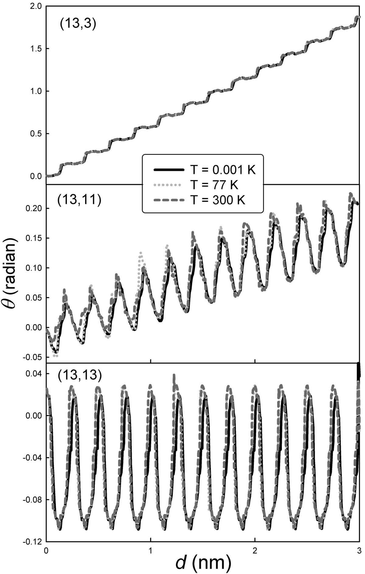
The functional relation between and the displacement rate cannot be quantitatively predicted here since the energy-minimization simulation does not represent actual displacements as functions of time; however, the same qualitative phenomenon will appear in molecular dynamics (MD) because of the kinetic energy of the system Wang and Devel (2011); Guo et al. (2015). I therefore perform MD simulations to check the effect of temperature on the motion transmission behavior of the BNNT by using the Nosé-Hoover thermostat with a time step of 1 femtosecond Plimpton (1995); Wang (2018); Wu et al. (2019); Li et al. (2013); Lin et al. (2014). Fig. 4 shows the rotation angle of NT2 when NT2 is made to slide at three different temperatures, , (liquid nitrogen temperature) and K. The comparison between the results at the three temperatures shows that the rotation angle remains almost the same for the tested pairs. However, it can be seen that the kinetic energy adds uncertainty to the displacement of BNNTs due to the random movement of the atoms that increases the probabilities of trajectories away from the potential energy minima.
It is found that the aforementioned motion transmission is reversible, in the sense that NT2 will slide along its axis if the driving NT1 rotates. NT2 will also rotate at the same time. We find that the sliding distance and the rotation angle of NT2 are well-defined functions of the rotation angle of NT1. Two dimensionless factors can be defined to represent the efficiency of this motion transmission,
| (7) |
is the translational factor with measured in radians, and
| (8) |
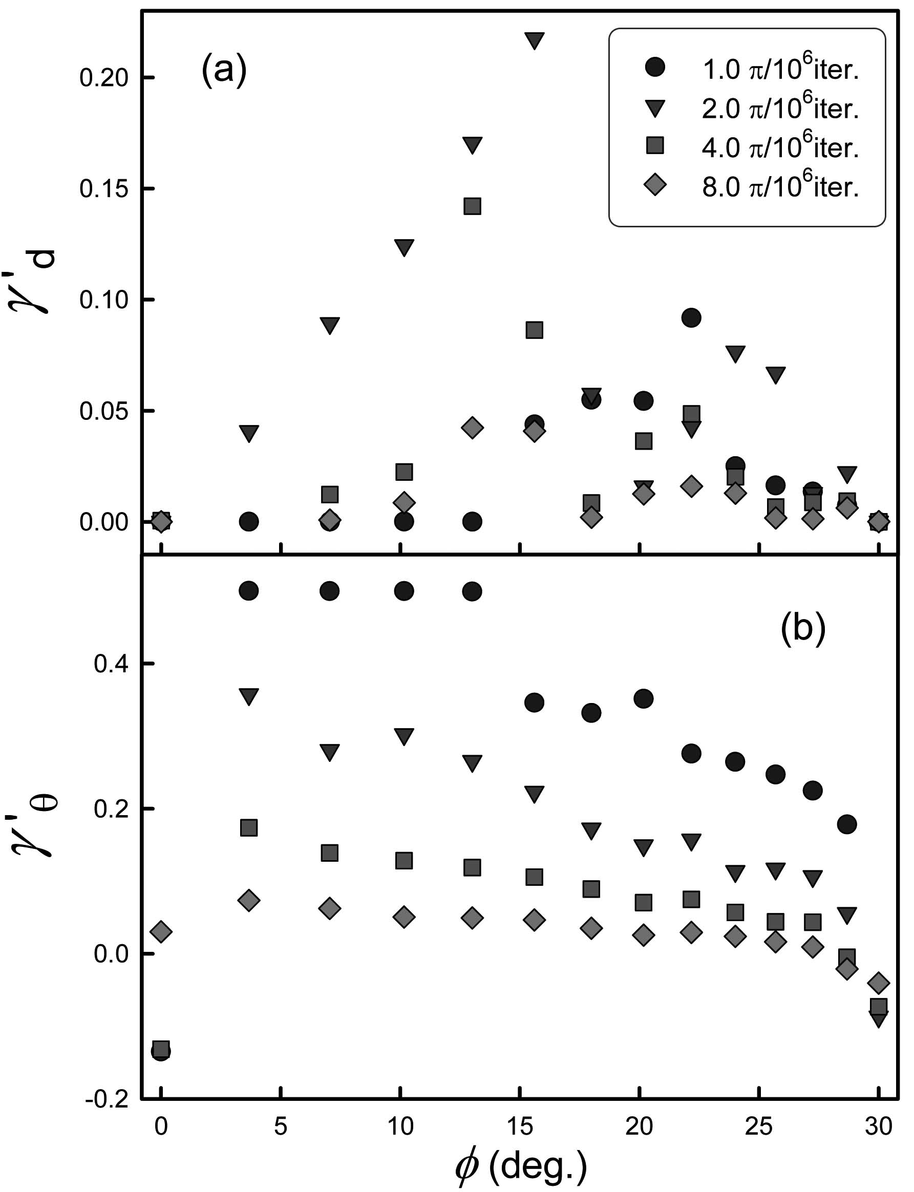
is the rotational factor. It can be seen from Fig. 5 that increases with increasing and reaches a maximum at , before it decreases to about zero for the armchair BNNT. is almost zero at low rotation rates of the NT1, it has a maximum value at an intermediate rotation rate, and decreases when the NT1 rotates faster. decreases with increasing except for the zigzag BNNT, and increases with decreasing rotation rates of the NT1.
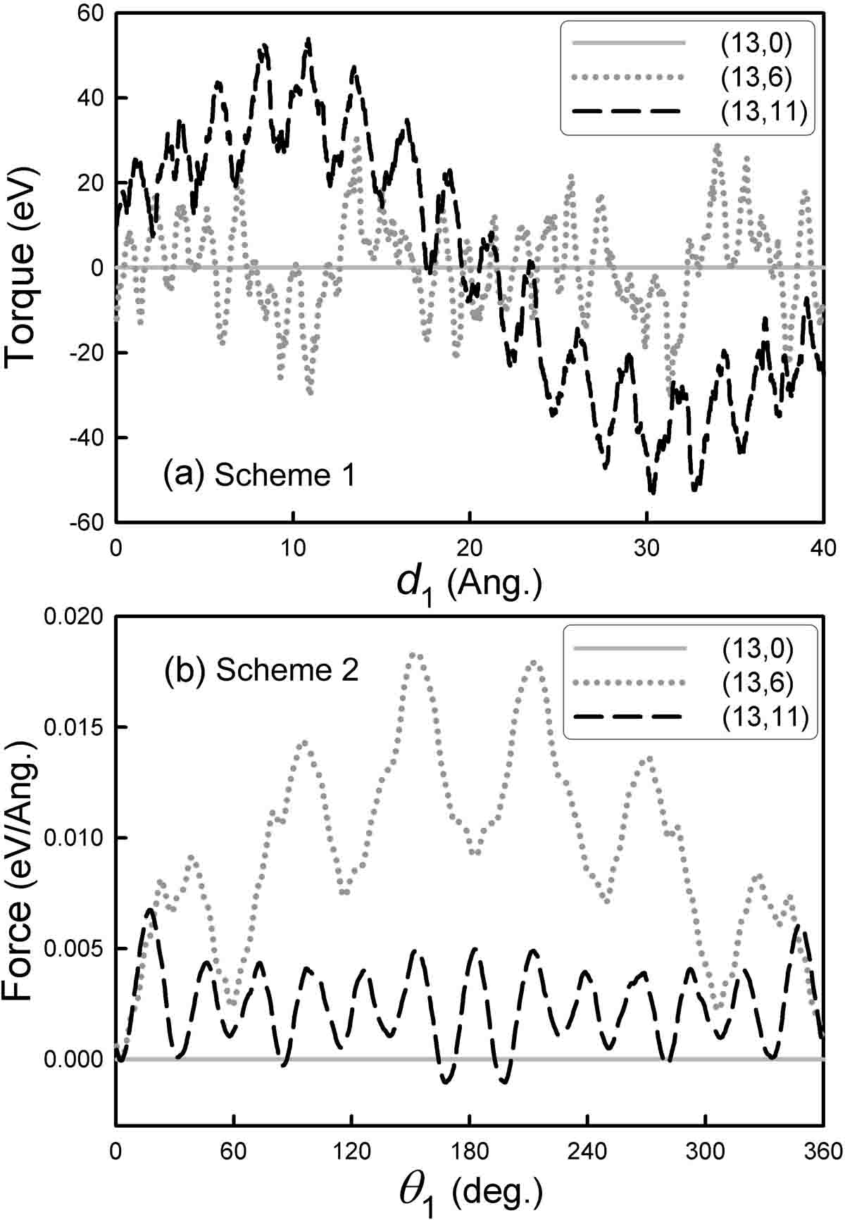
An interesting question is how much mechanical load can be transmitted between the tubes in a parallel junction. The magnitude of the transferable torque and force depends on the specific boundary configuration. In the aforementioned simulations, the driven tube (NT2) is free to move in the plane normal to its axis. Such a system can be used to transmit motion but cannot be used to transmit load since the inter-tube distance is adjusted spontaneously and the inter-tube normal stress tends to be zero. To transmit force and torque, the inter-tube distance needs to be fixed through the application of an external pressure between the tubes, just like when fixing the positions of the central axis of two gears before meshing their teeth to transmit power. To study this scenario, additional simulations are carried out with a fixed inter-tube distance of . A rough estimation of the torque and the force is performed when NT1 is made to slide [Fig. 6(a)] or to rotate [Fig. 6(b)]. The torque and the force acting on NT2 vary with different BNNT types. It is observed that the torque and the force are almost zero for the zigzag BNNTs and are higher for the chiral ones, and that they reach up to and per angstrom of tube length, respectively.
III.2 Cross Junctions
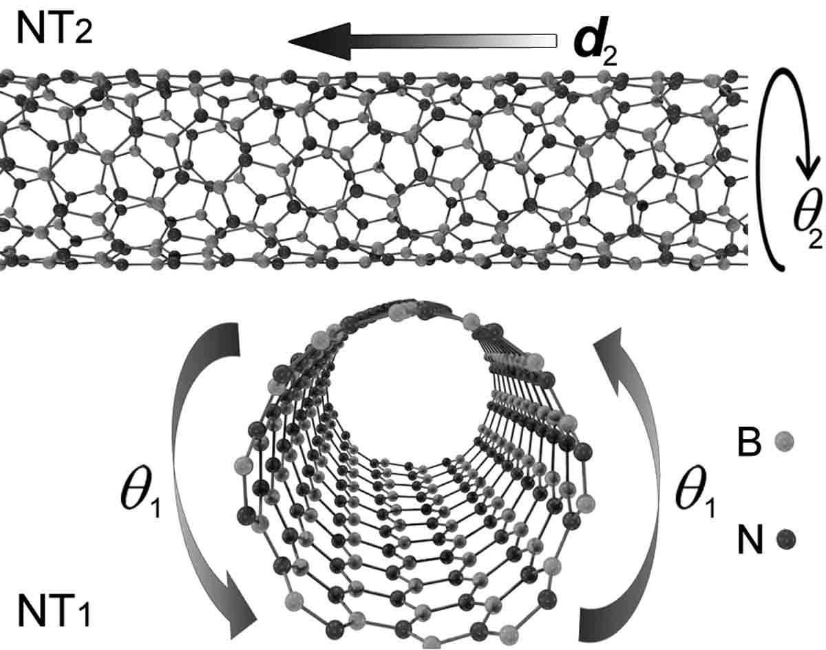
The cross junction of BNNTs can also be used to transmit motion. As shown in Fig. 7, two BNNTs are placed perpendicular to each other in non-covalent interaction. NT1 is then made to rotate around its axis in analogy to experiments Fennimore et al. (2003); Cohen-Karni et al. (2006) with a rotation rate of per iteration of steps. The displacement and the rotation angle of the NT2 are then measured as functions of .
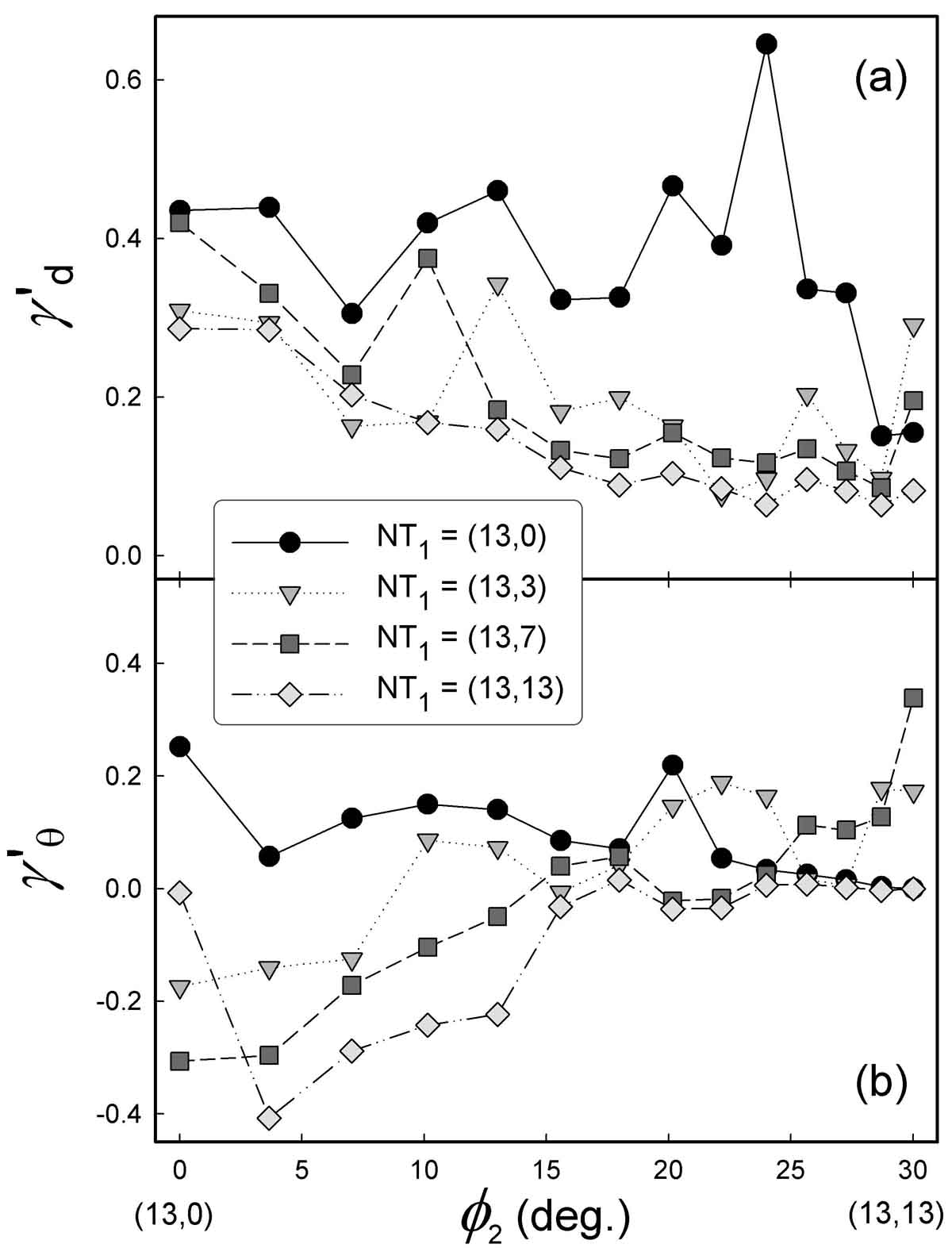
In Fig. 8, we plot and as functions of the chiral angle of the NT2 for different possible NT1. is found to decrease with increasing and is in general larger for the zigzag NT1 and lower for the armchair one. Unlike , which always has positive values, can be either positive (counterclockwise rotation) or negative (clockwise rotation) depending on the bi-chirality. is found to be negative for and to increase with increasing , except for the zigzag tube. It deceases to about zero for the armchair NT2. is higher for certain tube pairs with a preference for large . The data are from simulations with pairs of BNNTs with different combinations of chiralities. A complete list of these bi-chiral BNNT pairs and their motion transmission factors are provided in the Supporting Information.
IV Conclusion
In conclusion, significant chirality-dependent gear effects are revealed at BNNT parallel and cross junctions. Atoms are used as gear teeth to transmit power orthogonally via long-range interactions. By this atomistic mechanism, the translational motion of a BNNT can be spontaneously translated into a rotation of the adjacent one, and viceversa. At parallel junctions, the rotational motion transmission factor decreases linearly with the increasing chiral angle, while the translational one has a maximum at an intermediate value. The chirality dependence is attributable to different potential energy landscapes formed from different stacking sequences. The displacement rate also exhibits influence on the efficiency of the motion transmission. The magnitudes of the transmittable force and torque are estimated for parallel junctions. The transmission efficiency of BNNT cross junctions shows preference for tubes of a small size with a large bi-chirality. The atomistic gear mechanism has important implications for the design of mechanical power/speed transmission systems using nanostructured junctions.
References
- Needham (1965) J. Needham, Science and Civilisation in China, Volume 4: Physics and Physical Technology, Part 2, Mechanical Engineering (Cambridge University Press, 1965).
- Rapenne and Joachim (2017) G. Rapenne and C. Joachim, Nat. Rev. Mater. 2, 17040 (2017).
- Kassem et al. (2017) S. Kassem, T. van Leeuwen, A. S. Lubbe, M. R. Wilson, B. L. Feringa, and D. A. Leigh, Chem. Soc. Rev. 46, 2592 (2017).
- Badjic et al. (2004) J. D. Badjic, V. Balzani, A. Credi, S. Silvi, and J. F. Stoddart, Science 303, 1845 (2004).
- Brouwer et al. (2001) A. M. Brouwer, C. Frochot, F. G. Gatti, D. A. Leigh, L. Mottier, F. Paolucci, S. Roffia, and G. W. H. Wurpel, Science 291, 2124 (2001).
- Pantarotto et al. (2008) D. Pantarotto, W. R. Browne, and B. L. Feringa, Chem. Comm. 13, 1533 (2008).
- Kim et al. (2007) S. H. Kim, D. B. Asay, and M. T. Dugger, Nano Today 2, 22 (2007).
- Zhang et al. (2017) Z. H. Zhang, E. S. Penev, and B. I. Yakobson, Chem. Soc. Rev. 46, 6746 (2017).
- Arenal et al. (2010) R. Arenal, X. Blase, and A. Loiseau, Adv. Phys. 59, 101 (2010).
- Golberg et al. (2010) D. Golberg, Y. Bando, Y. Huang, T. Terao, M. Mitome, C. C. Tang, and C. Y. Zhi, ACS Nano 4, 2979 (2010).
- Wang (2019) Z. Wang, J. Phys. Chem. C 123, 15166 (2019).
- Marom et al. (2010) N. Marom, J. Bernstein, J. Garel, A. Tkatchenko, E. Joselevich, L. Kronik, and O. Hod, Phys. Rev. Lett. 105, 046801 (2010).
- Kolmogorov et al. (2004) A. N. Kolmogorov, V. H. Crespi, M. H. Schleier-Smith, and J. C. Ellenbogen, Phys. Rev. Lett. 92, 085503 (2004).
- Falvo et al. (2000) M. R. Falvo, J. Steele, R. M. Taylor, and R. Superfine, Phys. Rev. B 62, R10665 (2000).
- Chen et al. (2013) Y. B. Chen, Z. Y. Shen, Z. W. Xu, Y. Hu, H. T. Xu, S. Wang, X. L. Guo, Y. F. Zhang, L. M. Peng, F. Ding, et al., Nature Comm. 4, 2205 (2013).
- Sinclair et al. (2018) R. C. Sinclair, J. L. Suter, and P. V. Coveney, Adv. Mater. 30, 1705791 (2018).
- Guerra et al. (2017) R. Guerra, I. Leven, A. Vanossi, O. Hod, and E. Tosatti, Nano Lett. 17, 5321 (2017).
- Cai et al. (2014) K. Cai, H. Yin, Q. H. Qin, and Y. Li, Nano Lett. 14, 2558 (2014).
- Barreiro et al. (2008) A. Barreiro, R. Rurali, E. R. Hernandez, J. Moser, T. Pichler, L. Forro, and A. Bachtold, Science 320, 775 (2008).
- Gilbert et al. (2019) S. M. Gilbert, T. Pham, M. Dogan, S. Oh, B. Shevitski, G. Schumm, S. Liu, P. Ercius, S. Aloni, M. L. Cohen, et al., 2D Mater. 6, 021006 (2019).
- Wang (2018) Z. Wang, J. Phys. D Appl. Phys. 51, 435301 (2018).
- Falin et al. (2017) A. Falin, Q. R. Cai, E. J. G. Santos, D. Scullion, D. Qian, R. Zhang, Z. Yang, S. M. Huang, K. Watanabe, T. Taniguchi, et al., Nature Comm. 8, 15815 (2017).
- Nigues et al. (2014) A. Nigues, A. Siria, P. Vincent, P. Poncharal, and L. Bocquet, Nature Mater. 13, 688 (2014).
- Zeng et al. (2010) H. B. Zeng, C. Y. Zhi, Z. H. Zhang, X. L. Wei, X. B. Wang, W. L. Guo, Y. Bando, and D. Golberg, Nano Lett. 10, 5049 (2010).
- Wang and Philippe (2009) Z. Wang and L. Philippe, Phys. Rev. Lett. 102, 215501 (2009).
- Wang (2009) Z. Wang, Carbon 47, 3050 (2009).
- Wang et al. (2010) Z. Wang, L. Philippe, and J. Elias, Phys. Rev. B 81, 155405 (2010).
- Wang et al. (2007) Z. Wang, M. Devel, R. Langlet, and B. Dulmet, Phys. Rev. B 75, 205414 (2007).
- Wang and Devel (2007) Z. Wang and M. Devel, Phys. Rev. B 76, 195434 (2007).
- Tersoff (1988) J. Tersoff, Phys. Rev. B 37, 6991 (1988).
- Los et al. (2017) J. H. Los, J. M. H. Kroes, K. Albe, R. M. Gordillo, M. I. Katsnelson, and A. Fasolino, Phys. Rev. B 96, 184108 (2017).
- Tang et al. (2011) D. M. Tang, C. L. Ren, X. L. Wei, M. S. Wang, C. Liu, Y. Bando, and D. Golberg, ACS Nano 5, 7362 (2011).
- Thamwattana and Hill (2007) N. Thamwattana and J. M. Hill, J. Phys.: Condens. Matter 19, 406209 (2007).
- Kolmogorov and Crespi (2005) A. N. Kolmogorov and V. H. Crespi, Phys. Rev. B 71, 235415 (2005).
- Maaravi et al. (2017) T. Maaravi, I. Leven, I. Azuri, L. Kronik, and O. Hod, J. Phys. Chem. C 121, 22826 (2017).
- Reguzzoni et al. (2012) M. Reguzzoni, A. Fasolino, E. Molinari, and M. C. Righi, Phys. Rev. B 86, 245434 (2012).
- Zhao et al. (2014) Y. D. Zhao, X. M. Chen, C. Park, C. C. Fay, S. Stupkiewicz, and C. H. Ke, J. Appl. Phys. 115, 164305 (2014).
- Qi et al. (2018) H. Qi, S. Picaud, M. Devel, E. Liang, and Z. Wang, Astrophys. J. 867, 133 (2018).
- Vilhena et al. (2016) J. G. Vilhena, C. Pimentel, P. Pedraz, F. Luo, P. A. Serena, C. M. Pina, E. Gnecco, and R. Perez, ACS Nano 10, 4288 (2016).
- Dienwiebel et al. (2004) M. Dienwiebel, G. S. Verhoeven, N. Pradeep, J. W. M. Frenken, J. A. Heimberg, and H. W. Zandbergen, Phys. Rev. Lett. 92, 126101 (2004).
- Verhoeven et al. (2004) G. S. Verhoeven, M. Dienwiebel, and J. W. M. Frenken, Phys. Rev. B 70, 165418 (2004).
- Schoen et al. (2006) P. A. E. Schoen, J. H. Walther, S. Arcidiacono, D. Poulikakos, and P. Koumoutsakos, Nano Lett. 6, 1910 (2006).
- Wang and Devel (2011) Z. Wang and M. Devel, Phys. Rev. B 83, 125422 (2011).
- Guo et al. (2015) W. Guo, Z. Wang, and J. Li, Nano Lett. 15, 6582 (2015).
- Plimpton (1995) S. Plimpton, J. Comp. Phys. 117, 1 (1995), ISSN 0021-9991.
- Wu et al. (2019) Z. Wu, X. Yang, and Z. Wang, Nanotechnology 30, 245601 (2019).
- Li et al. (2013) X. Li, J. Carrete, J. Lin, G. Qiao, and Z. Wang, Appl. Phys. Lett. 103, 103902 (2013).
- Lin et al. (2014) J. P. Lin, X. D. Li, G. J. Qiao, Z. Wang, J. Carrete, Y. Ren, L. Z. Ma, Y. J. Fei, B. F. Yang, L. Lei, et al., J. Amer. Chem. Soc. 136, 1497 (2014).
- Fennimore et al. (2003) A. M. Fennimore, T. D. Yuzvinsky, W. Q. Han, M. S. Fuhrer, J. Cumings, and A. Zettl, Nature 424, 408 (2003).
- Cohen-Karni et al. (2006) T. Cohen-Karni, L. Segev, O. Srur-Lavi, S. R. Cohen, and E. Joselevich, Nature Nanotech. 1, 36 (2006).