Chirality-Dependent Motion Transmission between Aligned Carbon Nanotubes
Abstract
I demonstrate a directional motion-transmission behavior of aligned carbon nanotubes (CNTs) using atomistic simulations. The network of overlapping orbitals at the interface act as gear teeth to translate the sliding motion of a CNT into a rotating motion of the adjacent CNT, or viceversa. The efficiency of this orthogonal motion transmission is found to strongly depend on the tube chirality, by which the interfacial stacking configuration of the atoms is determined. These results have strong implications on the design of the motion transmission system at the nanoscale.
I Introduction
The miniaturization of devices and machines down to the nanometer scale presents exciting opportunities for various applications, half a century after the prescient prediction by Richard Feynman at an American Physical Society meeting banquet on Dec. 29, 1959 Ieong et al. (2004). Taming the mechanical motion of the nanodevices is one of the major challenges in taking the miniaturization technology envisioned by Feynman beyond mundane geometric scaling. For instance, considerable attention has recently been devoted to the “top-down” design of nano-machines such as molecular cars Shirai et al. (2006), motors Kassem et al. (2017), elevators Badjic et al. (2004) and shuttlesBrouwer et al. (2001). Light can be used as the power input of such molecular machines Erbas-Cakmak et al. (2015), however the induced motion is rather random due to the lack of a motion-transmission system, which is the key component in most machines and devices with moving parts. Such a problem remains critical for the design of nano-machines inspired by their macroscopic-world counterparts. The difficulties arising at the nanoscale include not only the synthesis of structures with well positioned cut-teeth, but also the strong friction and adhesion caused by a dramatic increase in the surface-to-volume ratio Kim et al. (2007).
Carbon nanotubes (CNTs) have received considerable attention with a view to their use as components in nanoscale devices thanks to their unique mechanical properties and peculiar one-dimensional structure Dong et al. (2007). The possibility of a gear effect has theoretically been proposed for CNTs with benzyne-derived teeth Han et al. (1997). However, attaching molecules at specific positions on the CNT surface is way beyond the resolution of the present chemical functionalization technology Pantarotto et al. (2008). Recently, a screw-like motion has been reported for shells in concentric CNTs Cai et al. (2014); Kolmogorov and Crespi (2000); Bourlon et al. (2004), with the potential to achieve directional molecule transport with low friction Guerra et al. (2017). Furthermore, the interaction between CNTs and substrates was found to strongly depend on the interface registry Kolmogorov et al. (2004); Falvo et al. (2000); Chen et al. (2013); Sinclair et al. (2018). Can these surface-interaction features of CNTs be used to design a motion-transmission system without needing precise chemical functionalization? Here we demonstrate a motion-transmission behavior of aligned CNTs by means of molecular mechanics. The chirality-dependent interaction between two aligned CNTs is used to convert the axial sliding of a driving tube into a rotating motion of the adjacent one, or viceversa.
II Method
The CNT exhibits a chiral structure that can be characterized by a pair of indices and , which define a helical circumferential vector in the hexagonal carbon lattice Dresselhaus et al. (2001). In our simulations, we consider a pair of infinite single-walled CNTs (denoted as CNT1 and CNT2) that are aligned side by side in the van der Waals (VDW) adhesion. This consideration is important because the CNTs as prepared by chemical vapor deposition (CVD) are often in bundle alignment Ren et al. (1998). Two experimentally-possible scenarios are considered. In the first case, CNT1 is made to slide axially with a constant rate of nm per iterations while the atoms in CNT2 are constrained to move in the plane normal to its axis as shown in Fig. 1 (a). In the second scheme, CNT1 is caused to rotate around its axis with a rate of per iterations, while the CNT2 atoms are set to be free in vacuum. The response of CNT2, driven by the motion of CNT1, is simulated by a molecular mechanics procedure in which a metastable state (a motionless equilibrium atomistic configuration of the atoms) is computed at each iteration by minimizing the total potential energy of the system using a gradient descent algorithm Wang and Devel (2007); Wang et al. (2007); Wang (2009). We here use the molecular mechanics instead of the molecular dynamics Guo et al. (2015); Wu et al. (2019) in order to avoid the thermal noise. Note that the pressure between the CNTs holds roughly zero since the inter-tube spacing is allowed to change during the simulation in the both schemes. The simulation schemes are demonstrated by the video recordings provided in the Supplemental Materials.
is given by the sum of the pairwise covalent and long-range interactions,
| (1) |
where , , and are indices of atoms, and are the total number of atoms in CNT1 and CNT2, respectively. The first and second terms on the right side of Eq.1 represent the potential energy of the covalent bonds of the CNT1 and the CNT2 respectively. They are given by the second generation of reactive empirical bond-order (REBO) force field, in which the total interatomic potential involves many-body terms,
| (2) |
where and denote the interatomic repulsion and attraction terms between the valence electrons, respectively. represents the effect of single-bond torsion. The many-body effects are included in the bond-order function , which depends on the atomic distance, the bond angle, the dihedral angle and the bond conjugation. The parameterization and benchmarks for this potential have been provided elsewhere (Brenner et al., 2002). The REBO potential is reported to afford a good description of the structural flexibility of low-dimensional carbons Wang and Philippe (2009); Wang and Devel (2011); Wang (2018); Qi et al. (2018).
The Lennard-Jones (LJ) force field is employed to describe the inter-tube interaction potential ,
| (3) |
with a potential well depth of , an equilibrium distance of and a cutoff radius of (Stuart et al., 2000). The LJ potential has been reported to underestimate the surface energy corrugation Kolmogorov and Crespi (2005); Sinclair et al. (2018). We therefore compared the results obtained by using the LJ force field with those based on the more sophisticated Kolmogorov-Crespi (KC) force field, which has been reported to give an improved description to the overlap of -orbitals between two graphene layers at a high load Kolmogorov and Crespi (2005). The comparison, however, reveals only minor differences between the KC and LJ models in the context of our simulations, as shown in the Supplemental Materials. This may be due to the fact that our CNTs are placed in vacuum and the interfacial pressure is therefore about zero. Hence, the inter-tube force strongly depends on the position of the peaks of the interaction potential surface, while the depth of the potential well has a far weaker effect.
III Results and Discussion
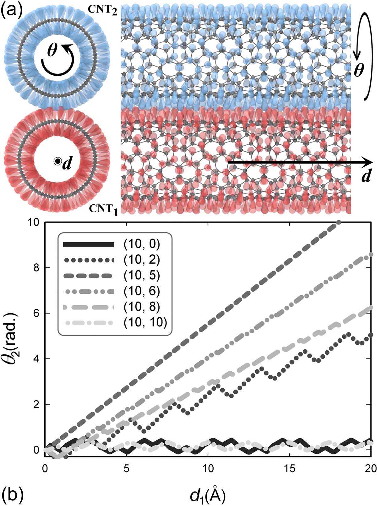
We first consider the simple case of two aligned identical CNTs in the first simulation scheme. A spontaneous rotation of CNT2 is observed when CNT1 is caused to slide along its axis in the direction shown in Fig. 1 (a). Let us denote the rotation angle of the CNT2 by , and plot its values in Fig. 1 (b) versus the sliding distance () of CNT1. A directional motion transmission behavior is observed. Roughly, is proportional to with different proportionality constants for different CNT pairs. For instance, a (10,5) tube is found to rotate the most, with being a linear function of . In contrast, oscillations can be found in the curves for other tubes. In particular, the armchair (10,10) and zigzag (10,0) CNTs rotate back and forth with a period in the variable of about Å and Å, respectively. These periodic lengths coincide with the dimensions of an orthogonal unit cell of the CNT Dresselhaus et al. (2001).
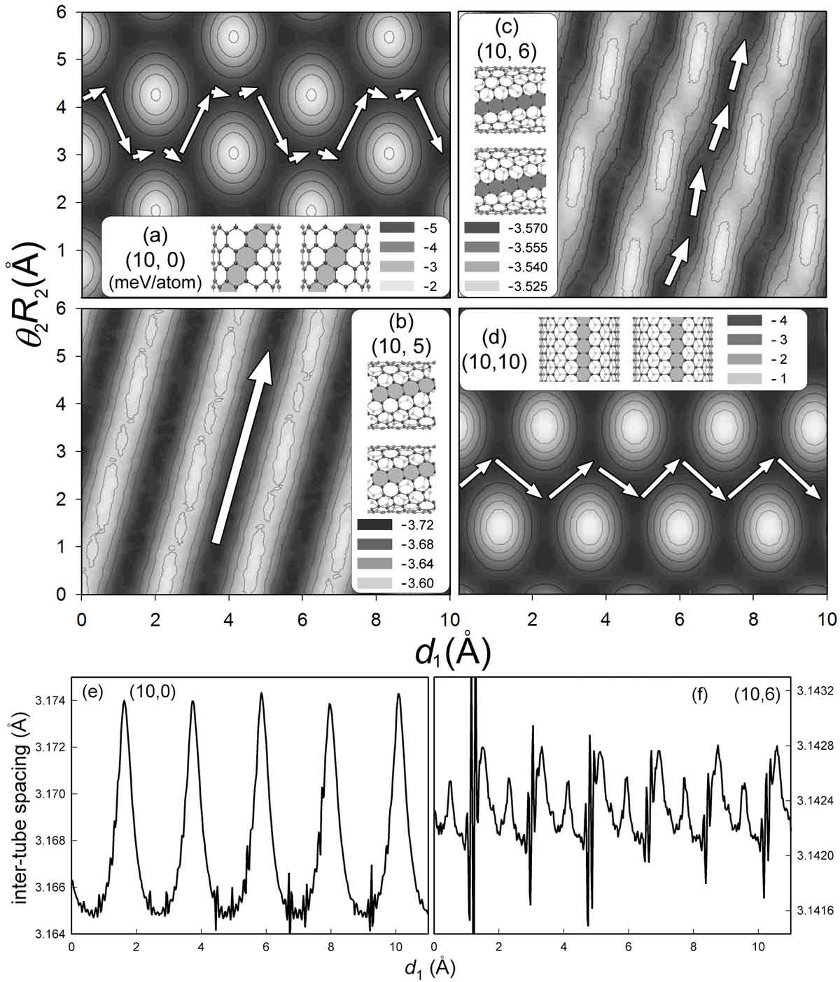
Why is there such motion transmission between the aligned CNTs, and why does it show a strong dependence on the chirality? The CNTs exhibit quasi- hybridization, wherein each carbon atom builds three in-plane bonds, leaving a -orbital pointing in the direction normal to the surface. This hybridization forms an atomic hill-and-valley potential landscape like the one shown in Fig. 2(a). When the CNTs are physically adsorbed together in van der Waals interaction, there will be some directions in which the CNTs can move over each other more easily than in other directions Dienwiebel et al. (2004). These optimized directions follow the principle to minimize the energy corrugation and strongly depend on the structure of CNTs. It has been shown in experiments that the interactions between CNTs and/or graphene sheets mainly depend on the registry of the electron bonds at the interface Chen et al. (2013); Falvo et al. (2000), which is determined by the CNT chirality Kolmogorov et al. (2004); Guerra et al. (2017). To progress towards a detailed explanation of this effect, we depict the distribution of the potential energy (DPE) of the inter-tube interaction for four different pairs of CNTs in Fig. 2. On the DPE, the rotation of CNT2 is represented by the change in the ordinate axis (where it has been multiplied by the tube radius to express it as a length), while the sliding of CNT1 is given by the variation in the abscissa axis. Without taking into account finite-temperature corrections, the change in in response to a slight variation of should always follow a minimum-energy trajectory. This forces the interface between two tubes to “surf” the waves of the DPE along a path corresponding to the lowest energy corrugation. Such energy-optimized paths (EOPs) are indicated by the arrows in Fig. 2.
The motion-transmission behavior of the aligned CNTs shown in Fig. 1 (b) can be explained by the EOP in the DPE landscape, since the shape and periodic length of these EOPs are consistent with those of the - curves in Fig. 1 (b). For instance, we see that the shape of the EOP of the (10,6) tubes is sinusoidal [Fig. 2 (c)], while that of the (10,5) tubes is almost a straight line [Fig. 2 (d)]. These coincide with the shape of the - curves of the corresponding tubes in Fig. 1 (b). We also observe the zigzag- and armchair-shaped EOPs in Figs.2 (a) and (d) for the (10,0) and (10,10) tubes, respectively. Note that is here used instead of for making a valid comparison between CNTs of different radii.
Moreover, we computed the inter-tube spacing as a function of the sliding distance for two different tube pairs as shown in Fig. 2 (e-f). The oscillation of the data is relatively small due to the fact that there is no temperature fluctuation and the tube is free to rotate in our simulations. The oscillation is smaller for the spacing between the (10,6) CNTs since they have shallower energy corrugation as shown in Fig. 2 (c). Benchmark density functional theory (DFT) calculations are performed for computing the potential energy of the interaction between CNTs versus the inter-tube distance as shown in the Supplemental Materials. It is seen that the equilibrium minimum distance is different for CNT pairs of different chirality. It ranges from to Å. The distance data in the Fig. 2 (e-f) calculated from classical simulations fall into this range. The minimum distance between two CNTs is usually smaller than that between two graphene layers (approximately Å) in graphite due to the effect of surface curvature. These results are roughly consistent with previous measurements of experiments Thess et al. (1996) and DFT calculations Charlier et al. (1995); Reich et al. (2002).
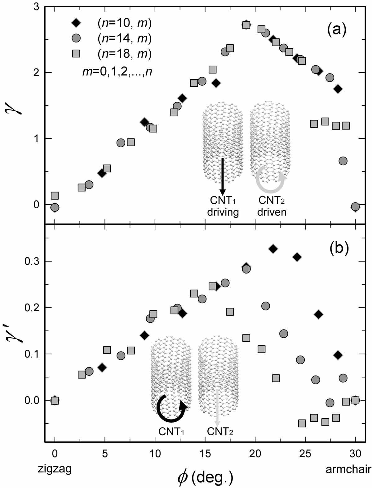
Fig. 1(b) shows that is roughly a linear function of . We can therefore define a dimensionless factor that represents the efficiency of motion transmission between two aligned CNTs,
| (4) |
To further quantify the chiral effect, in Fig. 3 (a) we plot as a function of the chiral angle , which is the angle between the chiral vector and the zigzag direction, and is equal to . It can be seen that is almost zero for the zigzag () tubes () since such a tube keeps oscillating instead of rotating. increases linearly with increasing before reaching a maximum at , namely the “magic” angle of CNTs Rao et al. (2012). then decreases to zero for the armchair () tubes beyond this threshold. This trend holds for the three different sets of CNT pairs of () with and . Note that can be greater than .
The rotation of CNTs has been realized in experiments Cohen-Karni et al. (2006). The motion-transmission behavior discussed above of two aligned CNTs should be reversible since they could function like a rack with a pinion. i.e., the rotation of one of the tubes should be able to induce a sliding motion of the other one. This is confirmed by our simulations of the second scheme, in which the CNT1 is made to rotate axially. Another transmission factor can be assigned to such a case as follows,
| (5) |
where and are the radius and the rotation angle of the driving CNT1, respectively, and is the sliding distance of the driven CNT2. is plotted in Fig. 3 (b) for pairs of identical CNTs. We see that increases linearly with increasing before reaching a critical chiral angle, and that it then decreases rapidly with increasing beyond this threshold. The critical chiral angle is not the same for the three sets of CNT pairs of different sizes, unlike the trend for . This difference may be due to different displacement rate and the fact that CNT2 is restricted not to move in the axial direction when measuring but it is left free for measuring .
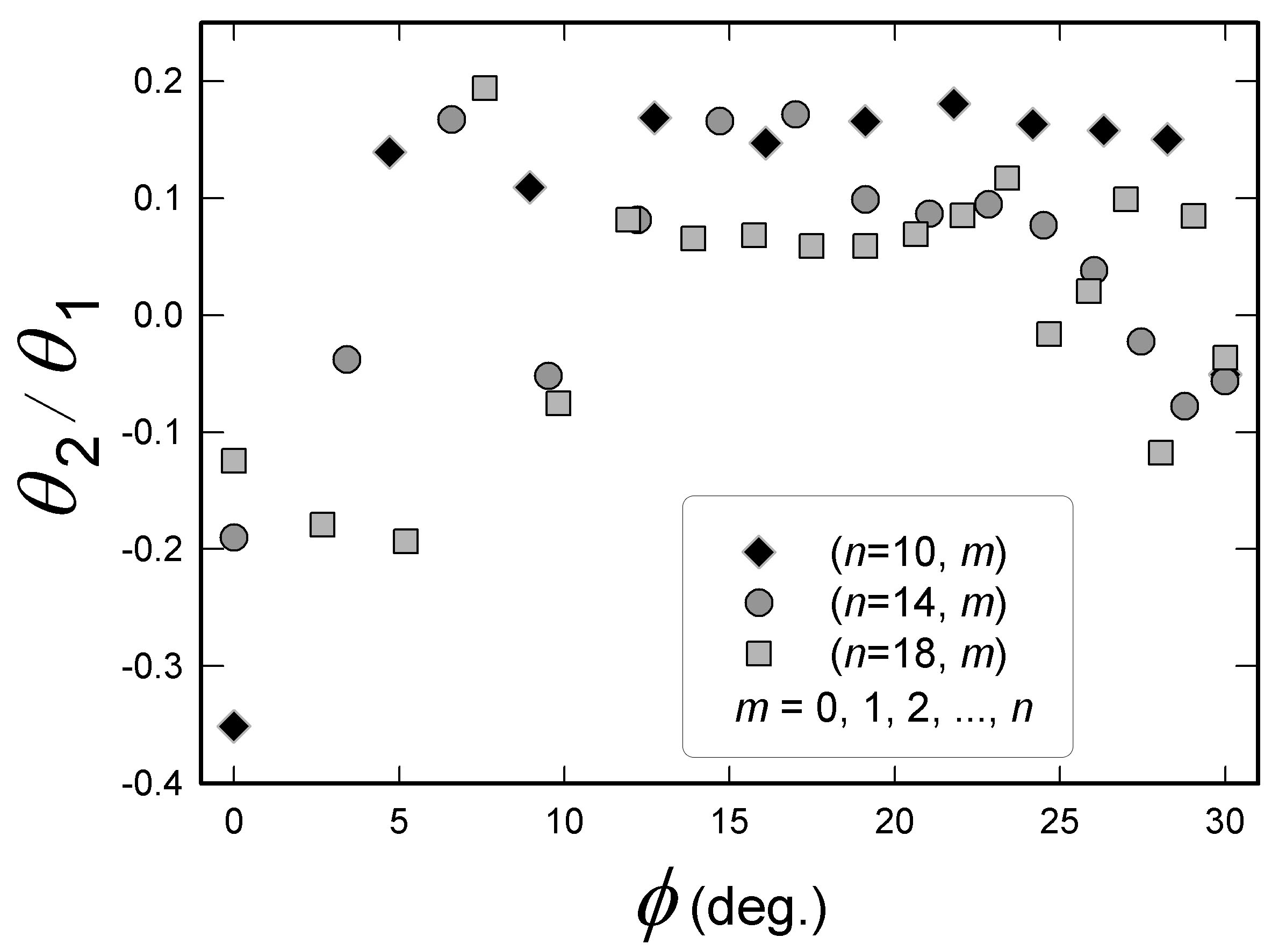
The CNT2 is observed to axially rotate when it is driven to slide by the rotation of CNT1 in the second simulation scheme. Its rotation angle also depends on the CNT chirality as shown in Fig. 4. The ratio can be either positive and negative. The CNT2 rotates in the same direction as the CNT1 does in case of positive , while it rotates in the inverse direction in case of negative . It can be seen that is negative for zigzag CNTs, and it increases to positive with increasing chiral angle until . It then roughly holds constant before decreasing back to negative values for armchair CNTs with increasing . The CNT radius also shows influence on the rotation of CNT2.
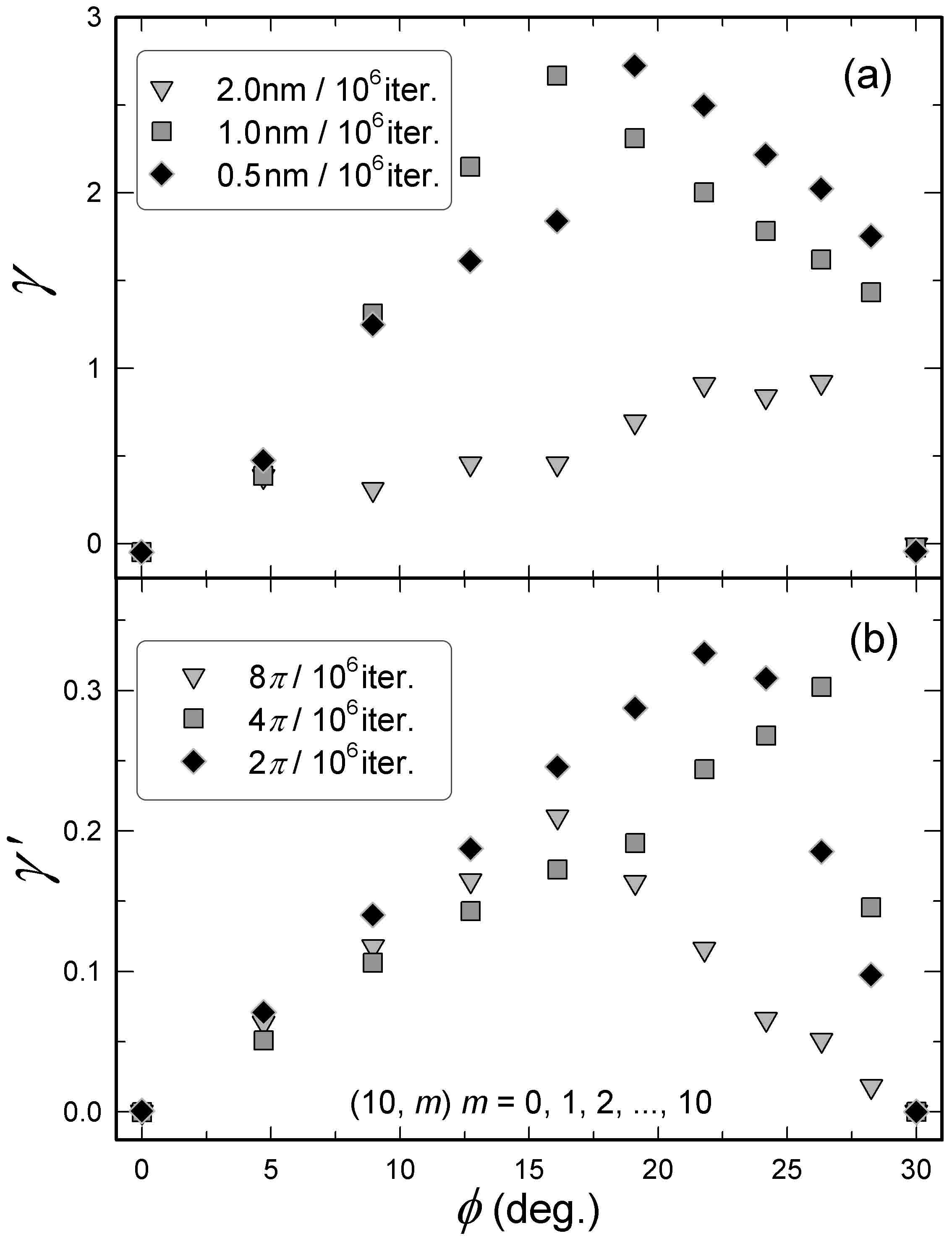
Sets of simulations are also carried out with different displacement rates for the both simulation scenarios. Fig. 5 shows the influence of the displacement rate on the motion transmission behavior of CNTs. It is seen that the motion transmission factor is lower when the driving tube moves faster in the first simulation scheme. The position of the peak of varies with different displacement rates. For the second simulation scheme, similar trend of the transmission factor holds for , it then changes with different rotating rate of the driving CNTs. These variations of the transmission factors qualitatively show the important influence of the displacement rate, although quantitative correlation between the transmission factors and the displacement rate cannot be accurately predicted as the time is not well defined by the present simulation method unlike that in molecular dynamics.

The aforementioned results are for identical CNTs. Does motion transmission exist between CNTs of different chirality? To answer this question, we have tested pairs of bi-chiral CNTs in the second simulation scheme. The measured transmission factor is plotted in Fig. 6 as a function of the chiral angles of both tubes. It is seen that is higher in absolute value for tube pairs of similar chirality, except in the armchair and zigzag cases. We also see that the axial sliding of CNT2 can happen in both ’forward’ or ’backward’ directions depending on the bi-chirality. The asymmetry of the landscape may be due to a small strain that is applied to the bi-chiral tubes with different lattice constants in order to keep the periodic boundary condition. The second scheme is chosen here since it has less artificially imposed boundary condition and considered to be more general than the first scheme. Moreover, we have simulated a CNT bundle composed of aligned (10,5) CNTs with a central driving tube which is caused to either slide along or rotate around its axis. The later is found to transmit motion: the surrounding tubes slide axially together when the central tube rotates, as shows in the Supplemental Materials. However, when a sliding is applied to the central tube, no rotation of the surrounding tubes is seen. Such a contrast to the two-tube setup is because the rotation motion is “locked” between the nearby CNTs.
Finally, we note that the effect of temperature is not involved in the present work using molecular mechanics simulations. However, the thermal effect will add uncertainty to the movement of the CNTs, since the distribution of the potential energy on a surface will become “fuzzy” when the temperature rises. In a previous work of Zhang et al. using molecular dynamics simulations, it was shown that the torque transmission efficiency between walls of concentric CNTs with confined water molecules decreases at increasing temperature Zhang et al. (2012). Similar effects can be expected on the motion transmission between aligned CNTs. Furthermore, since the driven CNT is free to move in the plane normal to its axis, the pressure between two CNTs is always about zero. The system studied in the present work can be used to transmit motion but can barely be used to transmit force and torque, since the inter-tube distance is adjusted spontaneously. To transmit force and torque, the inter-tube spacing needs to be fixed with external pressure applied between the CNTs. In this scenario, small and multi-walled CNTs may work better than large and single-walled ones owing to possible deformation of the CNT cross section under applied pressure.
IV Conclusion
In conclusion, we have demonstrated an orthogonal motion transmission between aligned CNTs. The sliding motion of a CNT can be spontaneously converted to a rotation of the neighboring ones, or viceversa. The motion-transmission factors are found to be well defined functions of the tube chiral angle. Analyses on the potential energy distribution show that this chirality dependence is attributable to the stacking of the helical lattice determining the overlap of the network of electron orbitals at the interface. This motion transmission behavior takes advantage of the strong interfacial adhesion between nanostructures, and is expected to be superlubric in nature Dienwiebel et al. (2004). It thus has important implications to the design of mechanical power transmission systems using nanomaterials with extreme surface-to-volume ratio.
References
- Ieong et al. (2004) M. Ieong, B. Doris, J. Kedzierski, K. Rim, and M. Yang, Science 306, 2057 (2004).
- Shirai et al. (2006) Y. Shirai, J.-F. Morin, T. Sasaki, J. M. Guerrero, and J. M. Tour, Chem. Soc. Rev. 35, 1043 (2006).
- Kassem et al. (2017) S. Kassem, T. van Leeuwen, A. S. Lubbe, M. R. Wilson, B. L. Feringa, and D. A. Leigh, Chem. Soc. Rev. 46, 2592 (2017).
- Badjic et al. (2004) J. D. Badjic, V. Balzani, A. Credi, S. Silvi, and J. F. Stoddart, Science 303, 1845 (2004).
- Brouwer et al. (2001) A. M. Brouwer, C. Frochot, F. G. Gatti, D. A. Leigh, L. Mottier, F. Paolucci, S. Roffia, and G. W. H. Wurpel, Science 291, 2124 (2001).
- Erbas-Cakmak et al. (2015) S. Erbas-Cakmak, D. A. Leigh, C. T. McTernan, and A. L. Nussbaumer, Chem. Rev. 115, 10081 (2015).
- Kim et al. (2007) S. H. Kim, D. B. Asay, and M. T. Dugger, Nano Today 2, 22 (2007).
- Dong et al. (2007) L. X. Dong, A. Subramanian, and B. J. Nelson, Nano Today 2, 12 (2007).
- Han et al. (1997) J. Han, A. Globus, R. Jaffe, and G. Deardorff, Nanotechnology 8, 95 (1997).
- Pantarotto et al. (2008) D. Pantarotto, W. R. Browne, and B. L. Feringa, Chem. Comm. 13, 1533 (2008).
- Cai et al. (2014) K. Cai, H. Yin, Q. H. Qin, and Y. Li, Nano Lett. 14, 2558 (2014).
- Kolmogorov and Crespi (2000) A. N. Kolmogorov and V. H. Crespi, Phys. Rev. Lett. 85, 4727 (2000).
- Bourlon et al. (2004) B. Bourlon, D. C. Glattli, C. Miko, L. Forro, and A. Bachtold, Nano Lett. 4, 709 (2004).
- Guerra et al. (2017) R. Guerra, I. Leven, A. Vanossi, O. Hod, and E. Tosatti, Nano Lett. 17, 5321 (2017).
- Kolmogorov et al. (2004) A. N. Kolmogorov, V. H. Crespi, M. H. Schleier-Smith, and J. C. Ellenbogen, Phys. Rev. Lett. 92, 085503 (2004).
- Falvo et al. (2000) M. R. Falvo, J. Steele, R. M. Taylor, and R. Superfine, Phys. Rev. B 62, 10665 (2000).
- Chen et al. (2013) Y. B. Chen, Z. Y. Shen, Z. W. Xu, Y. Hu, H. T. Xu, S. Wang, X. L. Guo, Y. F. Zhang, L. M. Peng, F. Ding, et al., Nature Comm. 4, 2205 (2013).
- Sinclair et al. (2018) R. C. Sinclair, J. L. Suter, and P. V. Coveney, Adv. Mater. 30, 1705791 (2018).
- Dresselhaus et al. (2001) M. S. Dresselhaus, G. Dresselhaus, and P. Avouris, eds., Carbon Nanotubes Synthesis, Structure, Properties, and Applications. (Springer-Verlag Berlin Heidelberg, 2001).
- Ren et al. (1998) Z. F. Ren, Z. P. Huang, J. W. Xu, J. H. Wang, P. Bush, M. P. Siegal, and P. N. Provencio, Science 282, 1105 (1998).
- Wang and Devel (2007) Z. Wang and M. Devel, Phys. Rev. B 76, 195434 (2007).
- Wang et al. (2007) Z. Wang, M. Devel, R. Langlet, and B. Dulmet, Phys. Rev. B 75, 205414 (2007).
- Wang (2009) Z. Wang, Carbon 47, 3050 (2009).
- Guo et al. (2015) W. Guo, Z. Wang, and J. Li, Nano Lett. 15, 6582 (2015).
- Wu et al. (2019) Z. Y. Wu, X. L. Yang, and Z. Wang, Nanotechnology 30, 245601 (2019).
- Brenner et al. (2002) D. Brenner, O. Shenderova, J. Harrison, S. Stuart, B. Ni, and S. Sinnott, J. Phys.: Condens. Matter 14, 783 (2002).
- Wang and Philippe (2009) Z. Wang and L. Philippe, Phys. Rev. Lett. 102, 215501 (2009).
- Wang and Devel (2011) Z. Wang and M. Devel, Phys. Rev. B 83, 125422 (2011).
- Wang (2018) Z. Wang, J. Phys. D: Appl. Phys. 51, 435301 (2018).
- Qi et al. (2018) H. Qi, S. Picaud, M. Devel, E. Liang, and Z. Wang, APJ 867, 133 (2018).
- Stuart et al. (2000) S. Stuart, A. Tutein, and J. Harrison, J. Chem. Phys. 112, 6472 (2000).
- Kolmogorov and Crespi (2005) A. N. Kolmogorov and V. H. Crespi, Phys. Rev. B 71, 235415 (2005).
- Dienwiebel et al. (2004) M. Dienwiebel, G. S. Verhoeven, N. Pradeep, J. W. M. Frenken, J. A. Heimberg, and H. W. Zandbergen, Phys. Rev. Lett. 92, 126101 (2004).
- Thess et al. (1996) A. Thess, R. Lee, P. Nikolaev, H. J. Dai, P. Petit, J. Robert, C. H. Xu, Y. H. Lee, S. G. Kim, A. G. Rinzler, et al., Science 273, 483 (1996).
- Charlier et al. (1995) J. C. Charlier, X. Gonze, and J. P. Michenaud, EPL 29, 43 (1995).
- Reich et al. (2002) S. Reich, C. Thomsen, and P. Ordejon, Phys. Rev. B 65, 155411 (2002).
- Rao et al. (2012) R. Rao, D. Liptak, T. Cherukuri, B. I. Yakobson, and B. Maruyama, Nature Mater. 11, 213 (2012).
- Cohen-Karni et al. (2006) T. Cohen-Karni, L. Segev, O. Srur-Lavi, S. R. Cohen, and E. Joselevich, Nature Nanotech. 1, 36 (2006).
- Zhang et al. (2012) Z. Q. Zhang, H. F. Ye, Z. Liu, J. N. Ding, G. G. Cheng, Z. Y. Ling, Y. G. Zheng, L. Wang, and J. B. Wang, J. Appl. Phys. 111, 114304 (2012).