Robust countermeasure against detector control attack in practical quantum key distribution system
Abstract
In real-life implementations of quantum key distribution (QKD), the physical systems with unwanted imperfections would be exploited by an eavesdropper. Based on imperfections in the detectors, detector control attacks have been successfully launched on several QKD systems, and attracted widespread concerns. Here, we propose a robust countermeasure against these attacks just by introducing a variable attenuator in front of the detector. This countermeasure is not only effective against the attacks with blinding light, but also robust against the attacks without blinding light which are more concealed and threatening. Different from previous technical improvements, the single photon detector in our countermeasure model is treated as a blackbox, and the eavesdropper can be detected by statistics of the detection and error rates of the QKD system. Besides theoretical proof, the countermeasure is also supported by an experimental demonstration. Our countermeasure is general in sense that it is independent of the technical details of the detector, and can be easily applied to the existing QKD systems.
pacs:
03.67.DdI Introduction
Quantum key distribution (QKD) is one of the most promising applications of quantum information. It enables two parties, Alice and Bob, to exchange key bits, whose security has been theoretically proved Quantumcryptography2002 ; lo1999unconditional ; RevModPhys2009 ; QuantumInfComput2004 ; Advances2019 . Unfortunately, real-life QKD systems still can be hacked due to the imperfection of the devices. Several kinds of attacks have been reported, such as photon-number-splitting (PNS) attack PNS1995 ; PNS2002 , phase-remapping attack phase-remapping2007 ; phase-remapping2010 , Trojan-horse attack gisin2006trojan , time-shift attack time-shift2007 ; time-shift2008 , wavelength-dependent attack wavelength-dependent2011 and detector control attack NatPhotonics2010 ; NatureCommun2011 ; thermalblind2010 ; after-gate2011 ; faint2011 ; laserdamage2014 ; passivequench2009 ; activequench2011 ; SNSPD2011 ; self-differencing2013 ; ATR . In order to defense these attacks, many countermeasures are also proposed, some of which are very effective and can even perfectly defense the corresponding attack, for example, decoy-state method is a perfect solution against PNS attack decoy ; decoy1 ; decoy2 ; decoy3 .
Recently, most attacks focus on the measurement equipment, especially on single-photon detectors (SPDs). Among which detector control attack is the most fatal one and has attracted lots of attentions NatPhotonics2010 ; NatureCommun2011 ; thermalblind2010 ; after-gate2011 ; faint2011 ; laserdamage2014 ; passivequench2009 ; activequench2011 ; SNSPD2011 ; self-differencing2013 ; ATR . To implement a detector control attack, Eve randomly chooses bases to measure the quantum states sent from Alice, then resends the results using trigger light with specific optical power. Due to the control effect of trigger pulses, the outputs of Bob’s detectors are nearly identical to Eve’s. This will cause zero or little extra error bits, and Eve can obtain a copy of raw keys without being revealed by legitimate users. Note that not all detector-related attacks belong to the detector control attack, such as the detector dead time attack weier2011quantum and time-shift attack time-shift2007 ; time-shift2008 are not within the scope of the detector control attack. In one of the most typical experiments NatPhotonics2010 , Eve first uses bright continuous-wave illumination to blind the SPDs, and converts them into linear detectors which are not sensitive to single photon. Then Eve can fully control the SPDs by sending trigger pulses that superimposed with the blinding light. There are a series of experiments using both blinding light and trigger light, such as continuous-wave blinding attack NatPhotonics2010 ; NatureCommun2011 , thermal blinding attack thermalblind2010 ; activequench2011 , sinkhole blinding attack thermalblind2010 . Furthermore, Eve need only send trigger light pulses to directly control SPDs, such as after-gate attack after-gate2011 , faint-after-gate attack faint2011 , detector control attack under specific laser damage laserdamage2014 . These detector control attacks without blinding light are more concealed and threatening to QKD systems than the ones with blinding light. In this sense, more attentions should be paid to detector control attack without blinding light.
There are various countermeasures to defense the detector control attack. The most ideal one is device-independent scheme acin2007device ; masanes2011secure , which excludes all the imperfections of the devices, but still impractical to applications of real-world use under current techniques. The most effective one is measurement-device-independent scheme MDI2012 ; Pirandola2012 , but it requires a Bell-state measurement of two independent remote laser sources, which is experimentally challenging. The other methods are mainly focusing on the technical improvements in SPDs lydersen2011secure ; Randomvariation2015 ; elezov2015countermeasures ; lee2016countermeasure or measurement devices honjo2013countermeasure ; wang2016countermeasures ; da2015safeguarding ; maroy2016secure , or passively monitoring parameters yuan2011resilience ; lydersen2011comment ; yuan2011response ; Real-timemonitoring2012 ; SWang2014 ; fujiwara2013characteristics ; meda2016backflash . However, these countermeasures may not be provably secure because the characteristics of actual devices and implementations are not under consideration in the security proofs lydersen2011comment ; lo2014secure . Furthermore, some countermeasures may be available to a kind of SPDs (Koehler2018, ) or effective to one specific attack, but not all types of detector control attack. For example, the method of monitoring the photocurrent of the avalanche photodiode is effective to find the detector control attack with blinding light, but will fail to detect the recent avalanche-transition region attack ATR . Another lately proposed countermeasure is to randomly remove gates and check the clicks in the absence of the gates Randomvariation2015 , while Eve can still implement traceless control of SPDs huang2016testing , since the method causes changes of both the gate signal leakage and gain factor in SPD circuits.
To defense detector control attack, we propose a robust countermeasure model by introducing a variable attenuator (VA) in front of the SPD. With the random change of attenuation of VA and the analysis of the corresponding detection events and errors, the countermeasure criteria is proven effective against the detector control attack without blinding light. An experiment is also demonstrated to support the effectiveness of the VA-SPD countermeasure. If Eve implements the detector control attack with blinding light, she would introduce new fingerprints in addition to high photocurrent, and trigger the alarm of the QKD system.
II countermeasure model
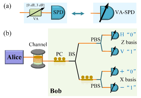
The implementation procedure of our countermeasure model is shown in Fig. 1(a), a VA is placed in front of the SPD, and its attenuation can be randomly changed among several values. Note that the number of attenuation values is at least two, and the value difference is (see APPENDIX A for an explanation of the necessity of ). In this paper, the number of attenuation values is two, and , respectively. The countermeasure model is named as VA-SPD, which is suitable for different kinds of SPDs, such as photomultiplier tubes (PMT), superconducting single-photon detector (SSPD) and semiconductor detectors (Si SPD, InGaAs/InP SPD). In the model, SPD is treated as a blackbox, which only has two ports: an optical signal input and a detection output. It is not necessary to modify the internal circuits or monitor the technical parameters in the SPD. So our countermeasure model is applicable for prepare-and-measure QKD systems, just by directly replacing the original SPD with a VA-SPD.
In order to explicitly illustrate the procedure of the proposed countermeasure model, we apply the VA-SPD to a typical polarization-encoding BB84 system with passive measurement bases selection, which has been hacked by several attacks wavelength-dependent2011 ; NatureCommun2011 ; liu2014universal ; lamas2007breaking ; nauerth2009information ; sajeed2015security ; weier2011quantum . As shown in Fig. 1(b), Alice prepares and sends Bob a sequence of polarization states, each randomly chosen from four polarization states {, , , }, and are horizontal and vertical polarization states, respectively. and denote and linear polarization states, respectively. For each state, Bob passively and randomly chooses one of the two measurement bases — Z (or rectilinear) basis and X (or diagonal) basis — to project the input photon into one of these four polarization states. At Bob’s site, each VA-SPD corresponds to one polarization state, and the attenuation value of VA in each VA-SPD is randomly set to or . After the announcement of basis choices, we can get the detection rate and quantum bit error rate (QBER) for each detector. Different from the original system, two kinds of results could be obtained for two values of VA in the VA-SPD. Here, for each VA-SPD, {, } and {, } denote the detection rates and QBERs with and attenuation value, respectively.
In almost all BB84 QKD systems, weak coherent states sources are widely used. The photon number of each pulse prepared by Alice follows a Poisson distributiondecoy3 . Suppose the expected photon number of each pulse is , the overall transmission and detection efficiency between Alice and Bob is , and the background rate is , then the detection rate is given by
| (1) |
which means the probability that Bob gets one detection count when Alice sends one pulse. For each detector, we can get similar expressions, the only differences are the meaning of and . Thus, the ratio between detection rates of one VA-SPD with and attenuation certainly satisfies
| (2) |
Additionally, the QBERs with and attenuation should be less than the threshold to generate secure keys. We have
| (3) |
where is the threshold of QBER, and is 11% for the four-state BB84 system securityproof1 ; securityproof2 ; securityproof3 .
In the BB84 QKD system employed VA-SPDs, the relationships of the detection rate Eq. (2) and QBER Eq. (3) between and attenuation should be held simultaneously. Here, we prove that the relationships of Eq. (2) and Eq. (3) cannot be satisfied simultaneously if the system was hacked by the detector control attack. This criteria would be a trace to find the detector control attack. And in the VA-SPD countermeasure model, we do not need open the SPD to monitor some specific parameters. Furthermore, the simulation results show that the fingerprint introduced by the detector control attack is pretty obvious.
II.1 Theoretical proof of the criteria
In all detector control attacks without blinding light, Eve first uses a random basis to measure the quantum state sent by Alice, then resends a trigger signal to Bob based on her measurement result. The power of the trigger signals is not in single-photon level, but in multi-photon level. And the power of the trigger signal stays the same, regardless of Eve’s measurement result. If Eve and Bob select matching bases, the trigger signal would hit one detector with full optical power. If Eve and Bob select opposite bases, the trigger signal would be split into two half parts and hit two detectors. According to the optical power (full, half) hitting the detector and the attenuation value (, ) of the VA-SPD, is defined as the detection probability with full optical power when the attenuation is . is likewise defined when the attenuation is ; similarly, with half power, and are defined as the detection probabilities when the attenuation are and , respectively. Suppose Eve select two measurement basis with equal probability, the detection rates of Bob’s one VA-SPD with and attenuation are given by
| (4) |
| (5) |
Here, “atk” means under the detector control attack.
As an acceptable assumption, both detectors in the same basis are identical here for simplicity. About the QBER of Bob’s one VA-SPD, it involves the other or orthogonal detector in the same basis. If both detectors click simultaneously, Bob assigns a random bit value. Since attenuation values of both VA-SPDs are changed independently, there are two circumstances: one is both VA-SPDs have the same attenuation value ( or ), the other is the attenuation values are opposite ( & , or & ). When both VA-SPDs have the same attenuation value, the QBER of Bob’s one VA-SPD with and attenuation are given by
| (6) |
| (7) |
For the detector control attack without blinding light, there are two equivalent situations — one is Eve and Bob select matching bases and the attenuation value of the corresponding VA-SPD is , the other is Eve and Bob select opposite bases and the attenuation value of the VA-SPD is . Then we have . From Eqs. (2),(4) and (5), we get
| (8) |
If the relationship of Eq. (3) is satisfied, we have
| (9) |
| (10) |
By adding both sides of these inequalities, we get
| (11) |
It’s obvious that this inequality cannot be satisfied in condition that , , and . Therefore, it is impossible to satisfy the relationships (Eq. (2) and Eq. (3)) simultaneously under the detector control attack.
Similarly, when the attenuation values of VA-SPDs are opposite, the QBER of Bob’s one VA-SPD with and attenuation are given by
| (12) |
II.2 Simulation results if one relationship is satisfied
According to the above proof, the relationships of Eq. (2) and Eq. (3) cannot be satisfied simultaneously under the detector control attack. Here, through the approach of numerical simulation, we show that the violation of one relationship would be pretty obvious if the other relationship is satisfied. Details of the calculation process is in Appendix. B.
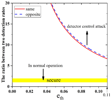
In the case that the relationship of Eq. (3) is satisfied, both QBERs ( and ) are less than . The bounds of the ratio between two detection rates are shown in Fig. 2. For the QKD system in normal operation, the ratio between two detection rates locates in the yellow region (). While, if the system was under the detector control attack, the lower bounds of the ratio between two detection rates are depicted by the red line and blue dashed line respectively, the red line () corresponds to the circumstance that both VA-SPDs in the same basis have the same attenuation value (denoted as same), and the blue dashed line () corresponds to the situation that these two attenuation values are opposite (denote as opposite). The slight difference between the red line and the blue dashed line comes from the discrepancy of QBERs in two circumstance (Eqs. (6)-(7) and Eqs. (12)-(13)). Obviously, the ratio between two detection rates under the detector control attack is far from the secure region, and as a good fingerprint, the detector control attack would be detected easily. As the threshold of QBER was set smaller, the ratio between two detection rates would be greater, and farther from the secure region. Even when is 11%, the lower bounds of in two situation are more than 6.5, which would be easy to find the attack.
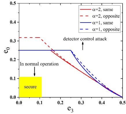
In the case that the relationship of Eq. (2) is satisfied, the ratio between two detection rates locates in the secure region. Fig. 3 illustrates the scales of QBERs with () and () attenuation. For the system in normal operation, both and should be less than 11%, as shown in the yellow region. Under the detector control attack, though Eve could control transmittance and number of trigger pulses to guarantee the detection rates unchanged, QBERs would increase a lot. In Fig. 3, the lines and dashed lines correspond to the situation that two attenuation values are the same and opposite, respectively. And, the red ones correspond to (upper bound of the ratio between two detection rates), the blue ones correspond to (lower bound of the ratio). It is obvious that and cannot be in the secure region together. If one of {, } was less than 11%, the other one would be more than 25%. Hence, these values of QBER would be very easy to trigger the alarm.
III Experimental demonstration of the countermeasure
To show the effectiveness of the countermeasure, we experimentally apply it against the faint after-gate attack faint2011 , which is a typical detector control attack without blinding light. The experimental setup is similar to the schematic depiction in Fig. 1(b). In the normal operation, Alice is the sender, who sends a sequence of polarization states with a repetition rate of 5 MHz and a expected photon number of each pulse. At Bob’s site, the random attenuation values of VA in VA-SPD are and , and the insertion loss of VA is approximately , which reduces the original detection efficiency of SPD 12.6% to a equivalent detection efficiency of VA-SPD 11.0% at attenuation. To simplify the experiment, Bob only monitors the detection events in Z basis , and always sets the same attenuation value ( or ) in the corresponding two VA-SPDs (the VA-SPD of bit “0” is used to detect the state, the VA-SPD of bit “1” is used to detect the state.) Hence, for the QKD system in the normal operation, the ratio between two detection rates is approximately 1.994, and QBERs with and attenuation values are 1.82% and 1.91%, respectively. While, under the faint after-gate attack, Eve becomes the sender, here we skip the intercept and measurement process for simplicity. Different from Alice, Eve needs first measure the characteristic of each SPD, and then carefully control the delay and incident flux of her encoded pulses, the delay makes these pulses arrive after the gate, and the incident flux (a few hundreds photons per pulse) offers superlinearity of the detection probability with full and half optical powers.
In order to keep the QBERs below the threshold, Eve chooses the attack positions at the falling edge of 0.74 ns and 0.88 ns for the VA-SPDs of bit “0” and bit “1”, respectively, and the incident flux of 108 photons per pulse. After measuring Eve’s encoded pulses in Z basis, the detection probabilities of Bob’s two VA-SPDs are listed in TABLE 1. Taking the VA-SPD of bit “0” for example, the detection probabilities with full and half incident flux are and , respectively, when the attenuation value is , and are and when the attenuation value is . Now the QBERs with two attenuation values are and , respectively. Both QBERs are below the threshold 11%, but the ratio between two detection rates is , far beyond the value in the normal operation. Thus this large ratio between two detection rates would make Bob detect the faint after-gate attack easily.
| (a) VA-SPD of bit “0” | (b) VA-SPD of bit “1” | |||
|---|---|---|---|---|
| Eve | ||||
| 0.10675 | 0.01415 | 0.00016 | 0.00011 | |
| 0.01413 | 0.00181 | 0.0142 | 0.0018 | |
| 0.0002 | 0.00019 | 0.10819 | 0.0144 | |
| 0.01427 | 0.00183 | 0.01416 | 0.00178 | |
The other attacking strategy is to keep the detection rates around the values in normal operation. This time Eve chooses the attack positions at the falling edge of 0.68 ns and 0.84 ns for the VA-SPDs of bit “0” and bit “1”, respectively, and the incident flux of 300 photons per pulse. After measuring Eve’s encoded pulses in Z basis, the detection probabilities of Bob’s two VA-SPDs are listed in TABLE 2. Still taking the VA-SPD of bit “0” for example, , , and , . Now the ratio between two detection rates is , close to the value in normal operation. But the QBERs with two attenuation values are , , both QBERs are more than ten times of the ones in normal operation. Hence this high QBERs would be pretty obvious to find the trace of Eve.
| (a) VA-SPD of bit “0” | (b) VA-SPD of bit “1” | |||
|---|---|---|---|---|
| Eve | ||||
| 0.9999 | 0.5015 | 0.0009 | 0.0004 | |
| 0.5019 | 0.2417 | 0.5018 | 0.2413 | |
| 0.0011 | 0.0005 | 0.9999 | 0.5024 | |
| 0.5012 | 0.2425 | 0.5023 | 0.2415 | |
Compared with normal QKD systems, the insertion loss of VA and the setting attenuation value would introduce extra attenuation and reduce the key rate. Nevertheless, these impacts can be weakened by choosing proper device and controlling the probability of setting attenuation. About the insertion loss of VA, there is no need to use high-speed intensity modulator since VA is controlled by Bob. In the experiment, the insertion loss of VA is only . About the impact of setting attenuation, the probability of setting could be very low in practice, and we can also reduce the impact of statistical fluctuation by accumulating longer time.
IV Effectiveness against the attack with blinding light
In the proof of the criteria of our countermeasure, there is an assumption that , which holds in the detector control attack without blinding light, but might fail in the attacks with blinding light. Hence the criteria of our countermeasure might not be deduced. However, in addition to high photocurrent yuan2011response , a new fingerprint would be introduced by the attack with blinding light in our countermeasure. So the proposed countermeasure is still effective against the attack with blinding light.
When the continuous-wave (CW) blinding light enters the VA-SPD, it is first modulated by the VA into full power or half power as the attenuation value is randomly set to or . In order to always blind the SPD, the modulated half power should be above the blinding power of the SPD, which is typically about dozens of microwatt huang2016testing . After the modulated blinding light hits the avalanche photodiode (APD), it will create a modulated train of photocurrent. Every time when the attenuation value of VA changes, a negative ( ) or positive ( ) signal will be generated at the output of the APD. This is the fingerprint left by the blinding light in the VA-SPD. And due to the relatively strong optical power of the blinding light, this fingerprint is fairly obvious and easy to be detected. Furthermore, superimposed with the capacitive noise of the gated APD, this fingerprint would exceed the discrimination voltage, and produce one click (or a few clicks), which has 50% probability to generate an error bit. Thus, even if we do not monitor the negative or positive signal at the output of the APD, the additional clicks introduced by the blinding light would increase the QBER and yield of the QKD system.
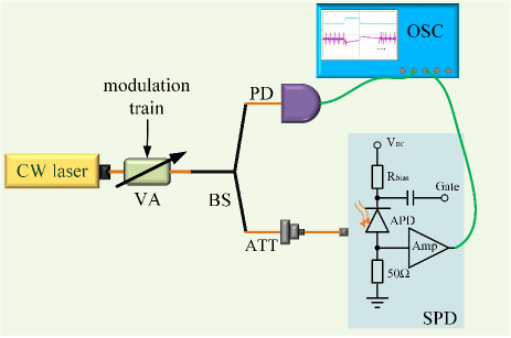
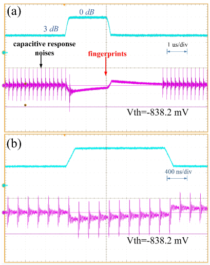
Although the detector is treated as a blackbox in the countermeasure model, as shown in Fig. 4, we open a detector and measure the output voltage to experimentally demonstrate the reason why Eve’s attack with blinding light would also be found. The CW laser modulated by the VA is splitted into two parts, one part enters a high-speed photodiode (PD) to show the characteristic of the modulated blinding light, the other part is first attenuated by an optical attenuator (ATT) to proper power, and then enters the APD, whose corresponding electrical signals are recorded by an oscilloscope to show the characteristic of the fingerprint left by the blinding light. The attenuation value of the VA is set to or , and the response time of VA is approximately ns. The SPD is operated at a frequency of 5 MHz, and can be blinded by a CW light at 1550 nm with a power from 11 W to 50 W. The results observed by the oscilloscope are shown in Fig. 5, the blue lines correspond to the modulated blinding light, and the fuchsine ones correspond to the electrical signals at the output of the APD. Here, the modulated blinding light that enters the APD has the power of 30 W (15 W) when the attenuation value of VA is (). In Fig. 5(a), the deadtime of SPD is 4.5 s, so we can observe the fingerprint left by the modulated blinding light clearly. Outside the modulated window, the blinding light is CW, there are only capacitive noises corresponding to the gating pulses. When the intensity changes from 15 W to 30 W, a negative signal is generated, and then decays during the unchanged intensity; when the intensity changes from 30 W to 15 W, a positive signal is generated, and also then decays during the unchanged intensity. Superimposed with the capacitive noises, the negative signal exceeds the discrimination voltage of -838.2 , and produces one click. In Fig. 5(b), the deadtime of SPD is set to bypass, the negative part superimposed with the capacitive noises produce about 9 clicks (fuchsine curve). These abnormal clicks can be easily detected by the VA-SPD, and trigger the alarm of the QKD system.
V conclusion
In this paper, we have proposed an effective countermeasure against the detector control attacks. After introducing a VA in front of the SPD, the VA-SPD model can detect the detector control attacks easily through analysis of the detection rates and QBERs corresponding to different attenuation values. We first focus on the detector control attacks without blinding light, which are more concealed and threatening to QKD systems. The criteria is proved that the relationships of the detection rate and QBER between and attenuation cannot be satisfied simultaneously once the system is hacked. In this countermeasure model against the detector control attack, the SPD is treated as a blackbox, we don’t need open it to monitor some specific parameters. By numerical simulations and the experimental application against the faint after-gate attack, we not only demonstrate the effectiveness of the VA-SPD model, but also show the obviousness of the fingerprint introduced by Eve. Furthermore, for the detector control attack with blinding light, we analyse and experimentally test the effectiveness of the VA-SPD model, in which a new fingerprint would be introduced in addition to high photocurrent. The countermeasure can be easily applied to the existing QKD system, and would provide a perfect balance between security and practicality.
Acknowledgments
This work has been supported by the National Key Research and Development Program of China (Grant Nos.2018YFA0306400), the National Natural Science Foundation of China (Grant Nos. 61622506, 61575183, 61822115, 61775207, 61627820), Anhui Initiative in Quantum Information Technologies.
Y-J. Q. and D-Y. H. contributed equally to this work.
Appendix A: analysis of the difference of VA’s value
In this section, we explain the reason why the VA’s value should differ . Assume that the attenuation value of VA in each VA-SPD is randomly set to and (). As mentioned above in Sec. II, after the announcement of basis choices, {, } and {, } denotes the detection rates and QBERs with and , respectively. For the QKD system in normal operation, the ratio between detection rates of one VA-SPD with and attenuation satisfies
| (14) |
similarly, the QBERs with and attenuation should be less than the threshold. We get
| (15) |
In detector control attack without blinding light, is defined as the detection probability with full optical power when the attenuation is . is likewise defined when the attenuation is ; similarly, with half power, and are defined as the detection probabilities when the attenuation are and , respectively. Suppose Eve select two measurement basis with equal probability. Then the detection rates with two attenuation values can be given by
| (16) |
| (17) |
For simplicity, we analyse the case that both VA-SPDs have the same attenuation value ( or ). Then the QBERs of Bob’s one VA-SPD with and attenuation values are given by
| (18) |
| (21) |
By adding both sides of these inequalities, we deduce that
| (22) |
As , and , we know that , . To make an effective countermeasure criteria, It should be guaranteed that Eq. (22) can not be satisfied for all the values of , there are two following cases:
If , whether the Eq. (22) can be satisfied depends on the value of , , and , which means that the countermeasure criteria is not general.
If , then , all the factors on the left of Eq. (22) is greater than 0, which is contradictory to the right result of Eq. (22). It means the two sub-cases: The one is the optical power before entering SPDs are equal, then half power with is equal to the full power with , so the difference of VA’s value between and is . It meets the requirement of generalization of criteria; The other one is the optical power before entering SPDs are different, but their detection probabilities are equal. Therefore, the countermeasure is influenced by the specific detector probabilities and is not general.
Appendix B: calculation process if one relationship is satisfied
When both VA-SPDs in the same basis have the same attenuation value, and in the case that both QBERs ( and ) are less than (Eq. (3) is satisfied), in order to deduce the range of , let , . Then Eqs. (6) and (7) can be converted into
| (23) |
| (24) |
With and we get
| (25) |
Then is given by
| (26) |
Define , then . Let , with Eq. (25) we have
| (27) |
We can simulate the lower bound of , the result is shown with the red line in Fig. 2.
Similarly, when both VA-SPDs in the same basis have the opposite attenuation value, and both QBERs ( and ) are less than , let , . Then Eqs. (12) and (13) can be converted into
| (28) |
| (30) |
Then we get the range of
| (31) |
Then is given by
| (32) |
Define , then , we have
| (33) |
We simulate the lower bound of , the result is shown with the blue dashed line in Fig. 2.
Under the detector control attack, since Eve could control transmittance and number of trigger pulses to guarantee the detection rates unchanged, is the attack transmission parameter which satisfies , then we have
| (34) |
| (35) |
When both VA-SPDs in the same basis have the same attenuation value, then , can be converted into
| (38) |
| (40) |
thus we substitute Eq. (40) to Eq. (38). We can simulate the relationship of the QBERs with () and (), we set for Eq. (37), because and are increasing with decreasing . If Eq. (40) is larger than 1 (smaller than 0), we take 1(0) for . The result is shown with red and blue lines in Fig. 3.
Similarly, when both VA-SPDs in the same basis have the opposite attenuation value, , can be converted into
| (41) |
| (42) |
According Eqs. (36) and (42), we get .
| (43) |
Take these equation to Eq. (41). We can simulate the relationship of the QBERs with () and (), we set for Eq. (37), because and are increasing with decreasing . Similarly, if Eq. (40) is larger than 1(smaller than 0), we take 1(0) for . The result is shown with red and blue dashed lines in Fig. 3.
References
- (1) N. Gisin, G. Ribordy, W. Tittel, and H. Zbinden, Quantum cryptography, Rev. Mod. Phys. 74, 145 (2002).
- (2) H.-K. Lo and H. F. Chau, Unconditional security of quantum key distribution over arbitrarily long distances, Science 283, 2050 (1999).
- (3) V. Scarani, H. Bechmann-Pasquinucci, N. J. Cerf, M. Dušek, N. Lütkenhaus, and M. Peev, The security of practical quantum key distribution[J]. Reviews of modern physics, Rev. Mod. Phys. 81, 1301 (2009).
- (4) D. Gottesman, H.-K. Lo, N. Lütkenhaus and J. Preskill, Security of quantum key distribution with imperfect devices, Quantum Inf. Comput. 4, 325 (2004).
- (5) S. Pirandola, U. L. Andersen, L. Banchi, M. Berta, D. Bunandar, R. Colbeck, D. Englund, T. Gehring, C. Lupo, C. Ottaviani, J. Pereira, M. Razavi, J. S. Shaari, M. Tomamichel, V. C. Usenko, G. Vallone, P. Villoresi and P. Wallden, Advances in Quantum Cryptography, arXiv:1906.01645 (2019).
- (6) B. Huttner, N. Imoto, N. Gisin, and T. Mor, Quantum cryptography with coherent states, Phys. Rev. A 51, 1863 (1995).
- (7) N. Lütkenhaus and M. Jahma, Quantum key distribution with realistic states: photon-number statistics in the photon-number splitting attack, New J. Phys. 4, 44 (2002).
- (8) C.-H. F. Fung, B. Qi, K. Tamaki, and H.-K. Lo, Phase-remapping attack in practical quantum-key-distribution systems, Phys. Rev. A 75, 032314 (2007).
- (9) F. Xu, B. Qi, and H.-K. Lo, Experimental demonstration of phase-remapping attack in a practical quantum key distribution system, New J. Phys. 12, 113026 (2010).
- (10) N. Gisin, S. Fasel, B. Kraus, H. Zbinden, and G. Ribordy, Trojan-horse attacks on quantum-key-distribution systems, Phys. Rev. A 73, 022320 (2006).
- (11) B. Qi, C.-H. F. Fung, H.-K. Lo, and X. Ma, Time-shift attack in practical quantum cryptosystems, Quantum Inf. Comput. 7, 73 (2007).
- (12) Y. Zhao, C.-H. F. Fung, B. Qi, C. Chen, and H.-K. Lo, Quantum hacking: Experimental demonstration of time-shift attack against practical quantum-key-distribution systems, Phys. Rev. A 78, 042333 (2008).
- (13) H. W. Li, S. Wang, J. Z. Huang, W. Chen, Z. Q. Yin, F. Y. Li, Z. Zhou, D. Liu, Y. Zhang, G. C. Guo, W. S. Bao, and Z. F. Han, Attacking a practical quantum-key-distribution system with wavelength-dependent beam-splitter and multiwavelength sources, Phys. Rev. A 84, 062308 (2011).
- (14) L. Lydersen, C. Wiechers, C. Wittmann, D. Elser, J. Skaar, and V. Makarov, Hacking commercial quantum cryptography systems by tailored bright illumination, Nat. Photonics 4, 686 (2010).
- (15) I. Gerhardt, Q. Liu, A. Lamas-Linares, J. Skaar, C. Kurtsiefer, and V. Makarov, Full-field implementation of a perfect eavesdropper on a quantum cryptography system, Nat. Commun. 2, 349 (2011).
- (16) L. Lydersen, C. Wiechers, C. Wittmann, D. Elser, J. Skaar, and V. Makarov, Thermal blinding of gated detectors in quantum cryptography, Opt. Express 18, 27938 (2010).
- (17) C. Wiechers, L. Lydersen, C. Wittmann, D. Elser, J. Skaar, C. Marquardt, V. Makarov, and G. Leuchs, After-gate attack on a quantum cryptosystem, New J. Phys. 13, 013043 (2011).
- (18) L. Lydersen, N. Jain, C. Wittmann, Ø. Marøy, J. Skaar, C. Marquardt, V. Makarov, and G. Leuchs, Superlinear threshold detectors in quantum cryptography, Phys. Rev. A 84, 032320 (2011).
- (19) A. N. Bugge, S. Sauge, A. M. M. Ghazali, J. Skaar, L. Lydersen, and V. Makarov, Laser damage helps the eavesdropper in quantum cryptography, Phys. Rev. Lett. 112, 070503 (2014).
- (20) V. Makarov, Controlling passively quenched single photon detectors by bright light, New J. Phys. 11, 065003 (2009).
- (21) S. Sauge, L. Lydersen, A. Anisimov, J. Skaar, and V. Makarov, Controlling an actively-quenched single photon detector with bright light, Opt. Express 19, 23590 (2011).
- (22) L. Lydersen, M. K. Akhlaghi, A. H. Majedi, J. Skaar, and V. Makarov, Controlling a superconducting nanowire single-photon detector using tailored bright illumination, New J. Phys. 13, 113042 (2011).
- (23) M.-S. Jiang, S.-H. Sun, G.-Z. Tang, X.-C. Ma, C.-Y. Li, and L.-M. Liang, Intrinsic imperfection of self-differencing single-photon detectors harms the security of high-speed quantum cryptography systems, Phys. Rev. A 88, 062335 (2013).
- (24) Y.-J. Qian, D.-Y. He, S. Wang, W. Chen, Z.-Q. Yin, G.-C. Guo and Z.-F. Han, “ Hacking the Quantum Key Distribution System by Exploiting the Avalanche-Transition Region of Single-Photon Detectors,” Phys. Rev. Appl 10, 064062 (2018).
- (25) W.-Y. Hwang, Quantum key distribution with high loss: toward global secure communication, Phys. Rev. Lett. 91, 057901 (2003).
- (26) H.-K. Lo, X. Ma, and K. Chen, Decoy state quantum key distribution, Phys. Rev. Lett. 94, 230504 (2005).
- (27) X.-B. Wang, Beating the photon-number-splitting attack in practical quantum cryptography, Phys. Rev. Lett. 94, 230503 (2005).
- (28) X. Ma, B. Qi, Y. Zhao, and H.-K. Lo, Practical decoy state for quantum key distribution, Phys. Rev. A 72, 012326 (2005).
- (29) H. Weier, H. Krauss, M. Rau, M. F¨urst, S. Nauerth, and H. Weinfurter, Quantum eavesdropping without interception: an attack exploiting the dead time of single-photon detectors, New J. Phys. 13, 073024 (2011).
- (30) A. Acín, N. Brunner, N. Gisin, S. Massar, S. Pironio, and V. Scarani, Device-independent security of quantum cryptography against collective attacks, Phys. Rev. Lett. 98, 230501 (2007).
- (31) L. Masanes, S. Pironio, and A. Acín, Secure device-independent quantum key distribution with causally independent measurement devices, Nat. Commun. 2, 238 (2011).
- (32) H.-K. Lo, M. Curty, and B. Qi, Measurement-device-independent quantum key distribution, Phys. Rev. Lett. 108, 130503 (2012).
- (33) S. L. Braunstein and S. Pirandola, Side-channel-free quantum key distribution, Phys. Rev. Lett. 108, 130502 (2012).
- (34) L. Lydersen, V. Makarov, and J. Skaar, Secure gated detection scheme for quantum cryptography, Phys. Rev. A 83, 032306 (2011).
- (35) C. C. W. Lim, N. Walenta, M. Legré, N. Gisin, and H. Zbinden, Random variation of detector efficiency: A countermeasure against detector blinding attacks for quantum key distribution, IEEE J. Sel. Top. Quantum Electron. 21, 192 (2015).
- (36) M. Elezov, R. Ozhegov, Y. Kurochkin, G. Goltsman, and V. Makarov, Countermeasures Against Blinding Attack on Superconducting Nanowire Detectors for QKD, in EPJ Web of Conferences, Vol. 103 (EDP Sciences, 2015) p. 10002.
- (37) M. S. Lee, B. K. Park, M. K. Woo, C. H. Park, Y.-S. Kim, S.-W. Han, and S. Moon, Countermeasure against blinding attacks on low-noise detectors with a background-noise-cancellation scheme, Phys. Rev. A 94, 062321 (2016).
- (38) T. Honjo, M. Fujiwara, K. Shimizu, K. Tamaki, S. Miki, T. Yamashita, H. Terai, Z. Wang, and M. Sasaki, Countermeasure against tailored bright illumination attack for DPS-QKD, Opt. Express 21, 2667 (2013).
- (39) J. Wang, H. Wang, X. Qin, Z. Wei, and Z. Zhang, The countermeasures against the blinding attack in quantum key distribution, Eur. Phys. J. D 70, 5 (2016).
- (40) T. F. da Silva, G. C. do Amaral, G. B. Xavier, G. P. Temporão, and J. P. von der Weid, Safeguarding Quantum Key Distribution through Detection Randomization, IEEE J. Sel. Top. Quantum Electron 21, 6600309 (2015).
- (41) Ø. Marøy, V. Makarov, and J. Skaar, Secure detection in quantum key distribution by real-time calibration of receiver, Quantum Sci. Technol. 2, 044013 (2017).
- (42) Z. L. Yuan, J. Dynes, and A. Shields, Resilience of gated avalanche photodiodes against bright illumination attacks in quantum cryptography, Appl. Phys. Lett. 98, 231104 (2011).
- (43) L. Lydersen, V. Makarov, and J. Skaar, Comment on ‘Resilience of gated avalanche photodiodes against bright illumination attacks in quantum cryptography’, Appl. Phys. Lett. 99, 196101 (2011).
- (44) Z. L. Yuan, J. Dynes, and A. Shields, Response to “Comment on ‘Resilience of gated avalanche photodiodes against bright illumination attacks in quantum cryptography’ ”, Appl. Phys. Lett. 99, 196101 (2011).
- (45) T. F. da Silva, G. B. Xavier, G. P. Temporão, and J. P. von der Weid, Real-time monitoring of single-photon detectors against eavesdropping in quantum key distribution systems, Opt. Express 20, 18911 (2012).
- (46) S. Wang, W. Chen, Z.-Q. Yin, H.-W. Li, D.-Y. He, Y.-H. Li, Z. Zhou, X.-T. Song, F.-Y. Li, D. Wang, H. Chen, Y.-G. Han, J.-Z. Huang, J.-F. Guo, P.-L. Hao, M. Li, C.-M. Zhang, D. Liu, W.-Y. Liang, C.-H. Miao, P. Wu, G.-C. Guo and Z.-F. Han, Field and long-term demonstration of a wide area quantum key distribution network, Opt. Express 22, 21739 (2014).
- (47) M. Fujiwara, T. Honjo, K. Shimizu, K. Tamaki, and M. Sasaki, Characteristics of superconducting single photon detector in DPS-QKD system under bright illumination blinding attack, Opt. Express 21, 6304 (2013).
- (48) A. Meda, I. P. Degiovanni, A. Tosi, Z. L. Yuan, G. Brida, and M.Genovese, Quantifying backflash radiation to prevent zero-error attacks in quantum key distribution, Light Sci. Appl. 6, e16261 (2017).
- (49) H.-K. Lo, M. Curty, and K. Tamaki, Secure quantum key distribution, Nat. Photonics 8, 595 (2014).
- (50) A. Koehler-Sidki, M. Lucamarini, J. Dynes, G. Roberts, A. Sharpe, Z. L. Yuan, and A. Shields, Intensity modulation as a preemptive measure against blinding of single-photon detectors based on self-differencing cancellation, Phys. Rev. A 98, 022327 (2018).
- (51) A. Huang, S. Sajeed, P. Chaiwongkhot, M. Soucarros, M. Legré, and V. Makarov, Testing random-detector-efficiency countermeasure in a commercial system reveals a breakable unrealistic assumption, IEEE J. Quantum Electron. 52, 1 (2016).
- (52) Q. Liu, A. Lamas-Linares, C. Kurtsiefer, J. Skaar, V. Makarov, and I. Gerhardt, A universal setup for active control of a single-photon detector, Rev. Sci. Instrum. 85, 349 (2014).
- (53) A. Lamas-Linares and C. Kurtsiefer, Breaking a quantum key distribution system through a timing side channel, Opt. Express 15, 9388 (2007).
- (54) S. Nauerth, M. Fürst, T. Schmitt-Manderbach, H. Weier, and H. Weinfurter, Information leakage via side channels in freespace BB84 quantum cryptography, New J. Phys. 11, 065001 (2009).
- (55) S. Sajeed, P. Chaiwongkhot, J.-P. Bourgoin, T. Jennewein, N. Lütkenhaus, and V. Makarov, Security loophole in free-space quantum key distribution due to spatial-mode detector-efficiency mismatch, Phys. Rev. A 91, 062301 (2015).
- (56) H.-K. Lo, H. F. Chau, and M. Ardehali, Efficient quantum key distribution scheme and a proof of its unconditional security, J. Cryptol. 18, 133 (2005).
- (57) B. Kraus, N. Gisin, and R. Renner, Lower and upper bounds on the secret-key rate for quantum key distribution protocols using one-way classical communication, Phys. Rev. Lett. 95, 080501 (2005).
- (58) R. Renner, N. Gisin, and B. Kraus, Information-theoretic security proof for quantum-key-distribution protocols, Phys. Rev. A 72, 012332 (2005).