Copyright Notice
©2019 IEEE. Personal use of this material is permitted. Permission from IEEE must be obtained for all
other uses, in any current or future media, including reprinting/republishing this material for advertising
or promotional purposes, creating new collective works, for resale or redistribution to servers or lists, or
reuse of any copyrighted component of this work in other works.
Published in: Proceedings of the 2019 International Conference on Indoor Positioning and Indoor Navigation (IPIN), 30 Sept. - 3 Oct. 2019, Pisa, Italy
DOI: 10.1109/IPIN.2019.8911742
A Generalized TDoA/ToA Model for ToF Positioning
Abstract
Many applications require positioning. Time of Flight (ToF) methods calculate distances by measuring the propagation time of signals. We present a novel ToF localization method. Our new approach works infrastructure-less, without pre-defined roles like Anchors or Tags. It generalizes existing synchronization-less Time Difference of Arrival (TDoA) and Time of Arrival (ToA) algorithms. We show how known algorithms can be derived from our new method. A major advantage of our approach is that it provides a comparable or better clock error robustness, i.e. the typical errors of crystal oscillators have negligible impact for TDoA and ToA measurements. We show that our channel usage is for most cases superior compared to the state-of-the art.
I Introduction
The term Time of Flight (ToF) refers to a class of methods which calculate distances by measuring propagation time of signals. When measuring ToF there are two main approaches to determine positions, Time of Arrival (ToA) and Time Difference of Arrival (TDoA). The most relevant approaches include Symmetrical Double Sided Two Way Ranging (SDS-TWR) [1], Asymetric Double Sided Two Way Ranging (asym-DS-TWR) [2], Whistle [3], Double Pulsed Whistle (DPW) [4] and the method published by Djaja-Josko and Kolakowski [5] which we will refer to as Djaja-Josko-Kolakowski-Method (DJKM).
All those methods are developed for specific setups. For example, some methods assume that the devices which are located are only capable to send signals (Whistle, DPW) or, vice versa, can only receive data (DJKM). Another important difference is that some methods have been developed for sound signals (e.g. Whistle) or radio signals (e.g. DPW, DJKM). The methods have all in common that no clock synchronization between devices is needed.
We have conducted a detailed analysis of those methods in a different publication [6]. While this paper is independent and self contained we recommend the lecture of that other work as an overview of the state-of-the-art of ToF methods.
One major drawback of the aforementioned methods is that they all need clearly defined roles of devices, e.g. there have to be Anchors with known positions which locate so called Tags. This restricts the ability to support infrastructureless-positioning, i.e. positioning without pre-defined roles or with changing roles. This makes it impossible for existing TDoA methods to determine relative positions between Nodes in scenarios where all devices are mobile.
Those scenarios include swarms of search and rescue drones, indoor navigation for firefighters and autonomous vehicle coordination.
This work is presenting a new method which can be seen as a generalization of the aforementioned methods in the sense that all existing methods can be derived from the proposed scheme. Our method, called Double Pulsed Positioning (DPP), can simultaneously perform ToA and TDoA. Even without any clock synchronization the errors induced by clockdrift are negligible. We show that our method outperforms the existing methods in terms of accuracy, flexibility and channel-utilization in almost all situations.
The rest of the paper is structured as follows. We introduce the new method and show how the other methods can be derived from it (Section II). The clock errors are analyzed and compared with other methods in Section III followed by the evaluation of DPP in Section IV. The work is concluded with a conclusion and future work.
II DPP System Overview
For the following definitions, we assume that any access to the ToF signal channel is coordinated by side communication channels (e.g. Wifi), and thus collisions (through simultaneous transmissions) are avoided. Also we assume that the Nodes can exchange information over a side channel.
We consider the devices’ clocks as imperfect with a typical clock drift accuracy of ppm. That means, we can not assume the devices to be synchronized nor to be running on one exact frequency. The only assumption we make over the device clocks is that their drift remains constant during one measurement cycle.
II-A Formal Definitions
As outlined in Section I, we are not differentiating between Anchors, Tags, Mirrors or such. Instead, all devices are represented as Nodes where each Node element is an element from the set of all Nodes . We define a function where is a Node and is a timestamp, that returns the cartesian coordinate of the Node at time . As a simplification, we write to refer to the current position of a Node. Further, we define that a System of Nodes is a subset of the available Nodes ().
A Node is further classified as one of three types:
-
•
Passive Nodes:
Nodes which are only capable of receiving data and never transmit something -
•
Active Nodes
Nodes which are only capable of transmitting data and never receive something -
•
Bilateral Nodes
Nodes which are capable of receiving and transmitting data
This differentiation makes up a partitioning of: :
We define to be the speed of the signal used when transmitting between Nodes (e.g., speed of light). The ToF between Nodes is defined as the euclidean distance between them divided through the signal velocity:
It follows that:
The TDoA between two Nodes in relation to signal source is, under the previous definition of Nodes, defined as:
| (1) |
In this document, representative Systems are sometimes selected as examples to visualize certain positioning scenarios. When Node Systems are presented in a figure, we use the following symbols:
-
•
Passive Nodes are labeled as and indexed individually by their suffix
-
•
This counts equivalently for Active () and Bilateral Nodes ()
-
•
Nodes with a known position (e.g., infrastructure mounted or Anchor devices) are depicted with a circle surrounding them
II-B DPP Operation Procedure and Message Diagram
The general operation-procedure of a DPP-Node-System is the following:
-
•
All of the Nodes in sequentially (turn-based) transmit two messages (Double Pulse)
-
•
All Nodes in listen constantly for any incoming messages
When each Active and Bilateral Node has communicated at least once, a so-called Cycle is completed. Fig. 1 shows an extract from such a sequence, and this way describes the different types of gathered measurements.
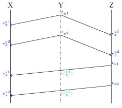
Each receiving timestamp is labeled as , where is the Node receiving, the Node transmitting, and is the index of the signal of this combination of receiver and sender in the current cycle. Similarly, the transmission timestamps are labeled as , where is the transmitting Node and is the index of that Node’s transmission in the current cycle with typically in the range of .
II-C TDoA Value
In the following, we derive a formula to calculate TDoA values based on the values generated by the DPP operation model (II-B).
When comparing the schematic Figures in this paper with DPW [4], we can see that some subsets of the message diagram resemble DPW schemes. That allows us to apply the tools provided by DPW to our measurements.
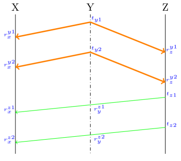
Depending on the operating modes of the Nodes (), up to two DPW sub-schemes can be derived from the situation shown in the diagram (Fig. 1). That is possible since the order of pulse and mirror is not fixed in DPW [4]. The signals of could therefore either be seen as a mirror-reply, or as a pulse to (potentially) capturing and . Vice-versa the signals of can be interpreted as pulse or as mirror-reply to and . Both sub-schemes are illustrated in Fig. 2. Attention, mind the different ordering of the Nodes compared to the original DPW paper.
We assume that in a System, operating in DPP-mode, any Node triple of the following form generates novel input information for a DPW calculation:
First we define the timespans we would measure with any such triple.
| (2) | ||||
| (3) | ||||
| (4) |
with being arbitrary but constant. It determines which of the two mirror-replies should be used for the DPW calculation. The choice of the pulse does not make a difference in theory. However, it can be used in practice to reduce the error. Such a reduction can be done for example by averaging results that are based on different s. Such a processing step can reduce the gaussian distributed measurement errors that might affect the mirror-replies’ timestamps.
Note that all lines except (2) and (3) contain measurement input from all three Nodes. This shows that they are dependent on them. Displaying this relationship motivates the difference in notation.
We then define compound variables for those measurements:
| (5) | ||||
| (6) | ||||
| (7) |
II-D ToA Value
In the following, we derive the formula which can be used to calculate ToA values based on the values generated by the DPP operation model (II-B).
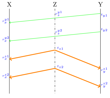
As we did with DPW, we can also identify up to two asym-DS-TWR schemes in the transmission diagram (Fig. 1). This becomes evident when inspecting an extract of the diagram and restructuring the visual representation as seen in Fig. 3. When assuming the role distribution , we can spot the two possible asym-DS-TWR measurements we can take.
Therefore, when performing DPP on a System of Nodes, any Node tuple fulfilling,
generates new input data for an asym-DS-TWR calculation (comp. [2]). Note that the Nodes generating this TWR input could simultaneously generate the mentioned DPW input.
For such a tuple the timespans measured can be expressed as follows:
is assumed arbitrary but constant. It determines which of the possible Double Sided Two Way Ranging (DS-TWR) paths to use. As with the in the TDoA derivation earlier (gaussian distributed) measurement errors, that affect the DS-TWR paths timestamps, can potentially be reduced.
III Error Analysis
In the following, we analyze DPP for its conditioning towards errors.
It is well known that clocks, or more precise the oscillators they are based on, in general contain imperfections [7]. That means that not even the highest quality clocks can be trusted with perfect timekeeping. Since ToF-based methods rely on measurements of signals propagating with very high speeds such as the speed of sound, or the speed of light , these imperfections pose a major problem regarding the accuracy of the localization.
As mentioned in Sec. II-A we assume a clock drift of ppm which is a typical value for crystal oscillators in the industry [8]. We model the clock drift by defining a worst case drift value for every device () clock separately: .
III-A TDoA Value Error
Since we deduced all our TDoA values based on the exact method described in DPW [4], we can conduct the error estimation in a very similar way.
First, the erroneous values are defined:
| and | |||
Then using (4), (5) and (6) it follows:
Where and designate the error with the calculation method (5) or (6). While represents the erroneous value resulting with application of the combining transformation from (7).
The overall worst-case error in the Node combination is then the difference between the true and erroneous value:
| (12) |
Consequently, the overall TDoA error follows:
We then add and subtract :
The maximal value can take on is apparently (that is the maximal difference of arrival time). Therefore we can assume , from what follows:
| (13) |
Which aligns with the error estimations from DPW [4]. That means that the TDoA value of the DPP method has the same worst case (clockdrift induced) error as DPW.
III-B ToA Value Error
We used the findings of the aysm-DS-TWR to calculate the distance values between two Bilaterals (II-D). We can therefore apply the same method for its error estimation. For all the DPP-method-term calculating (11) is besides a renaming () equivalent to the one described in the works of Neirynck et al. [2]. Therefore we can apply the same transformations to (11), which results in the error estimate:
| (14) |
Therefore the ToA (clock drift induced) error of DPP is equivalent to the one of asym-DS-TWR
III-C Error Analysis Summary
We can, therefore, estimate that the error each measurement can be characterized as:
and
In comparison with the worst-case error estimated of compared methods [4, 2, 1, 3, 5] the proposed method is always at least as well (error) conditioned as the compared ones.
The detailed and unified analysis and comparision of the errors of [4, 2, 1, 3, 5] can be found in our other publication [6].
Finally, it is noted that the equality stated in (18) does not necessarily translate for its errors. In other words, does not need to be equal to as they depend on different clocks. One depends on and the other on .
IV Evaluation of DPP
In the following, we analyze how DPP is related to other ToF method in the literature and how its TDoA and ToA calculation is improving existing methods..
IV-A Relation to other TDoA methods
We can then extend and re-arrange (8) with (1):
| (15) | ||||
Those equations can be interpreted as follows: With knowledge of one distance between either or we can use the measurement to calculate the TDoA value respectively .
If we compare the roles of the Nodes in the setup ( and ) we can make two observations:
DJKM can be derived
We look at the case , and , rename and remove the secondary pulses. Renaming is valid w.l.o.g. here as the capabilities of the Nodes we rename to include the capabilities we rename from.
DPW can be derived
As already mentioned, DPW schemes can be derived from the DPP scheme. In the case , and this is achieved by renaming and removing the second pulse from . Then this sub-scheme exactly resembles DPW (comp. [4]). Further, we calculate with DPP the exact same TDoA information (compare (8)) as the DPW that was derived would.
For the particular case we can also deduce:
| (16) | ||||
| (17) |
This value seems to be neither of the type ToA nor TDoA and is therefore of particular interest for acquiring a deeper understanding of the relation between ToA and TDoA. Nonetheless an analysis of the properties of this value would be out of the scope of this work and is subject to future work.
IV-B Accuracy Improvement
For situations in which we try to position a Passive Node the only known applicable method until now was DJKM (inv-Whistle). With DPP, there is now a new method for such situations. DJKM has in those cases a worst case TDoA error of:
| (19) |
The worst case TDoA error of DPP was previously shown (in Section III-A) to be:
| (20) |
is typically in the order of magnitude of milliseconds. It is usually many orders of magnitudes larger than , which is typically in the order of magnitudes of nanoseconds. Consequently, the accuracy of DPP is orders of magnitudes higher. This improvement can be attributed to the additional second pulse of DPP compared to DJKM. In situations where DPW or TWR are applicable, we have shown that DPP has the same worst-case error estimates (III-A and III-B).
IV-C Efficient Mobile Positioning
DPP solves the problem of mobile positioning by performing ToA and TDoA simultaneously. That way we only require a minimum of three Bilateral Nodes in our System to position the whole System. In practice, we recommend the use of four Bilateral Nodes for error correction.
Figures Fig. 4h and Fig. 4g show those two minimalistic examples of the new class of positioning situations that becomes available now. The positioning is achieved by first using the ToA values between the Bilateral Nodes to establish their relative positions and then using that information for TDoA-based positioning of the remaining Nodes.
IV-D New Cases
DPP further allows addressing some situations that could not be positioned by one existing method alone. We present some example of such setups:
IV-D1 More Flexible Positioning of a Passive Node
Until DPP the only method which could be used to position a Passive Node was DJKM. To generate TDoA-values for a Passive Node, DJKM requires an infrastructure of Bilateral Nodes [5]. DPP allows in such cases for other, more flexible device roles in the infrastructure.
For example the minimal setup to create three individual TDoA values for a Passive Node using DJKM is depicted in Fig. 4a. For DPP, the setups in figs. 4a, 4b, 4h and 4c are all sufficient constellations.
Concerning the TDoA solution engine, for practical reasons it is often even required to generate four TDoA values in order to position a Node sufficiently. Also for this requirement, DPP is an improvement. While DPP can be used to calculate four TDoA values in figs. 4e, 4g and 4f, DJKM will only work for the first case.


IV-D2 Mixed Tag Roles
All of the earlier presented known methods are limited to the one type (Active, Passive, Bilateral) of Tag they are positioning. With DPP, this restriction does not apply anymore. DPP allows for the combination of Active, Passive, and consequently Bilateral Tags to be positioned in the same operation cycle.
IV-D3 Gathering of TDoA and ToA values
Next to DJKM, DPP is the only method known to us, which generates ToA and TDoA values simultaneously. Moreover we have shown that DJKM has a worst-case error larger than DPP.
IV-E Improved Performance
Another benefit which comes with the generalization of TDoA and ToA methods into DPP is a reduction in redundancy. DPP uses in almost all cases equal or very often even fewer messages to gather the same set of measurements as the existing methods.
IV-E1 Improvement Compared to DPW
DPW requires to send three messages for every combination of Tags and Mirrors in the System [4]. For a given amount of Mirrors and Tags DPW needs at least messages for a complete operation cycle, where :
For instance, DPW needs signals when operating on the System displayed in Fig. 4d.
DPP requires for its operation to send two signals from every Active or Bilateral Node in the System. In comparison to DPW, DPP does require signals to operate one complete cycle on the same setup in Fig. 4d.
In general, the amount of signals required by DPP () for a system with Actives (“Tags”) and Bilaterals (“Mirrors”) is:
Even if we set “mirror-count” which resembles the situation in DPW, it is apparent that with an increasing number of Tags, DPP requires less signals to locate the same amount of Tags, due to the fact that
While the output of TDoA values generated are the same for both methods, DPP simultaneously yields ToA values and the new value type from (17).
It can be assumed that the situation (or even ) rarely occurs in real-world scenarios. Therefore in almost all realistic Node setups, the application of the DPP scheme improves a setup that was previously operated on the DPW scheme in terms of sent Nodes/signals.
IV-E2 Performance Improvement Against DJKM
When comparing DPP with DJKM, one has to bear the mentioned difference in accuracy (Sec. IV-B) in mind. However, even leaving this advantage aside, DPP outperforms DJKM.
To substantiate that statement, one has to realize the operation principle of DJKM as it is defined in the original paper [5]. DJKM specifies a distinct order after which Anchors should communicate with each other. This coordination is necessary to avoid collisions on the transmission medium. This specific order consists of two rounds. To describe the ordering, we consider our set of Anchors as an ordered list.
First Round
In the first round, as described in [5] each Anchor performs communication with its successor in the list. This process starts with the first Anchor in the list and ends with the last one. For example, the first Anchor interacts with the second, then the second interacts with the third, and so on.
Second Round
In the second round, only Anchors with an uneven index in the list communicate in the same sequential order with each other. Again, this starts with the first Anchor and ends with the last uneven Anchor. For example the first interacts with the third, then the third with the fifth, and so on.
This sequential chain of communicating Anchors can be reduced as shown in Fig. 5.

In this Figure, the first message emitted by is used to initialize the DJKM communication with the new Anchor device . From s perspective, this signal is still a reply in and ’s DJKM communication. For this signal resembles the initial message in and ’s DJKM communication. That way, the exchange of one signal can be saved whenever an Anchor has a predecessor since we can then reuse its reply message to the predecessor as the initial message for its successor. Note that the first Anchor in the list still has to transmit its initial message.
The number of signals () transmitted in one operation Cycle can therefore be calculated depending on the number of Anchors ():
| (21) | ||||
| (22) | ||||
| (23) |
Where and are the numbers of signals transmitted in the first and second round.
The DJKM System which uses the least amount of signals for gathering three TDoA s is shown in Fig. 4a. According to the formula derived, the amount of packages transmitted in this scheme is:
When using DPP, according to (IV-E1) this exact setup takes only signals to finish the DPP cycle. According to IV-A, it produces the exact same TDoA values.
In general, the signal requirements of every setup can be optimized by switching the scheme of operation from DJKM to DPP.
That can be argued as follows. A System of Anchors/Bilaterals and Tags/Passives operating on DJKM requires (23) signals. DPP requires for the exact same setup only signals. See (IV-E1).
Furthermore, DPP allows us in many situations to use Active instead of Bilateral Nodes while achieving the same result as DJKM would with all Nodes being bilateral. For instance 4b will yield in one DPP cycle the values and additionally . Applying (8) and (1), the resulting equation-set,
can then be transformed to
Under knowledge of the circled Nodes positions, this gives the TDoA values and . DJKM would result in Fig. 4a, a fully bilateral infrastructure with the measurement set , which is isomorphic.
The shown relaxation of restrictions does not only simplify the construction of positioning infrastructure. It also reduces the energy consumption of the whole network. That reduction roots in the fact that the energy consumption of radios that are commonly used for ToF is in practice orders of magnitudes larger when operating in RX mode rather than in TX [9].
IV-E3 Bilaterals
Bilateral Nodes can be interpreted as operating active and passive at the same time. It was already mentioned in Sec. IV-D2 that both types of Tags get processed in the same cycle when using DPP. This way, the preceding two paragraphs both apply simultaneously to any Tag with type Bilateral, generating the discussed TDoA values. That information can be used as input for a TDoA solver.
At the same time we already discussed that any pair of Bilaterals yields a ToA value through asym-DS-TWR when performing DPP. Again, this measurement comes at no additional performance cost as the same signals get used for TWR, DPW, and direct values at the same time. While the authors of DJKM mention that their System does measure ToA values between the Anchors, this does only work for certain pairs of Anchors [5]. It also does not work for Tag-Nodes with the role active or bilateral.
V Conclusion and Future Work
In this work we presented a novel ToF method, capable of tracking the relative positions of a large number of devices without the need for a fixed infrastructure. It is capable of collecting TDoA and ToA values simultaneously (TDoA: (8) and ToA: (11)).
We have proven our method to be more flexible, accurate, and efficient than existing methods.
Our ToF positioning is therefore suitable for applications such as swarm drone coordination, Indoor Navigation/Guidance, and autonomous driving.
Since we excluded the side channel communication between the nodes from our analysis, future work has to include the protocol overhead for coordination of the pulses of Active Nodes for a realistic implementation of the proposed method.
References
- Hach [2015] R. Hach, “Symmetric double sided two-way ranging.” IEEE 802.15.4a standard, doc. IEEE P.802.15-05-0334-00-004a, 6 2015.
- Neirynck et al. [2016] D. Neirynck, E. Luk, and M. McLaughlin, “An alternative double-sided two-way ranging method,” in 2016 13th Workshop on Positioning, Navigation and Communications (WPNC), 8 2016, pp. 1–4.
- Xu et al. [2011] B. Xu, R. Yu, G. Sun, and Z. Yang, “Whistle: Synchronization-free tdoa for localization,” in 2011 31st International Conference on Distributed Computing Systems, 6 2011, pp. 760–769.
- Tschirschnitz and Wagner [2018] M. V. Tschirschnitz and M. Wagner, “Synchronization-free and low power tdoa for radio based indoor positioning,” in 2018 International Conference on Indoor Positioning and Indoor Navigation (IPIN), 9 2018, pp. 1–4.
- Djaja-Josko and Kolakowski [2016] V. Djaja-Josko and J. Kolakowski, “A new transmission scheme for wireless synchronization and clock errors reduction in uwb positioning system,” 2016 International Conference on Indoor Positioning and Indoor Navigation (IPIN), pp. 1–6, 2016.
- Tschirschnitz et al. [2019] M. V. Tschirschnitz, M. Wagner, M. Oliver-Pahl, and G. Carle, “Clock error analysis of common time of flight based positioning methods,” in 2019 International Conference on Indoor Positioning and Indoor Navigation (IPIN), 9 2019, pp. 1–8.
- Allan et al. [1987] D. W. Allan et al., “Time and frequency(time-domain) characterization, estimation, and prediction of precision clocks and oscillators,” IEEE transactions on ultrasonics, ferroelectrics, and frequency control, vol. 34, no. 6, pp. 647–654, 1987.
- Jiang and Leung [2007] Y. Jiang and V. C. Leung, “An asymmetric double sided two-way ranging for crystal offset,” in 2007 International Symposium on Signals, Systems and Electronics. IEEE, 2007, pp. 525–528.
- Dec [2018] APS002 APPLICATION NOTE Minimizing Power Consumption in DW1000 Based Systems, Decawave Ltd., 10 2018, rev. 1.1.