11email: raphael.galicher at obspm.fr 22institutetext: Department of Astronomy, California Institute of Technology, Pasadena, CA 91125, USA 33institutetext: Jet Propulsion Laboratory, California Institute of Technology, Pasadena, CA 91109, USA
Minimization of non common path aberrations at the Palomar telescope using a self-coherent camera
Abstract
Context. The two main advantages of exoplanet imaging are the discovery of objects in the outer part of stellar systems – constraining the models of planet formation –, and its ability to spectrally characterize the planets – giving information on their atmosphere. It is, however, challenging, because exoplanets are up to times fainter than their star and separated by a fraction of arcsecond. Current instruments like SPHERE/VLT or GPI/Gemini detect young and massive planets, because they are limited by non-common path aberrations (NCPA) that are not corrected by the adaptive optics system. To probe fainter exoplanets, a new class of instruments capable of minimizing the NCPA is needed. One solution is the self-coherent camera (SCC) focal plane wavefront sensor, whose performance was demonstrated in laboratory attenuating the starlight by factors up to several in space-like conditions at angular separations down to .
Aims. In this paper, we demonstrate the SCC on the sky for the first time.
Methods. We installed an SCC on the stellar double coronagraph (SDC) instrument at the Hale telescope. We used an internal source to minimize the NCPA that limited the vortex coronagraph performance. We then compared to the standard procedure used at Palomar.
Results. On internal source, we demonstrated that the SCC improves the coronagraphic detection limit by a factor between and between and . Using this SCC calibration, the on-sky contrast is improved by a factor of between and . These results prove the ability of the SCC to be implemented in an existing instrument.
Conclusions. This paper highlights two interests of the self-coherent camera. First, the SCC can minimize the speckle intensity in the field of view especially the ones that are very close to the star where many exoplanets are to be discovered. Then, the SCC has a efficiency with science time as each image can be used for both science and NCPA minimization.
Key Words.:
instrumentation: adaptive optics, instrumentation: high angular resolution, techniques: high angular resolution1 Introduction
Imaging of exoplanets is one priority for astronomers because it is the only technique that can discover long orbital period planets and that enables the spectral characterization of their atmospheres. It is very challenging as the planets are to dimmer than their host star and at a fraction of arcsecond from their host star. Many coronagraphs were proposed to reduce the star diffraction pattern without changing the exoplanet image (Snik et al., 2018). Several are installed on the 8m class telescopes in instruments like SPHERE (Beuzit et al., submitted) and GPI (Macintosh et al., 2014) that were built to discover exoplanets by imaging. The coronagraphic images produced by these instruments enable the detection of planets that are up to times fainter than their star. Such performance is far from the best performance reached in laboratory with attenuation of the starlight by a factor of to (Baudoz et al., 2018b; Lawson et al., 2013). That is because wavefront aberrations upstream the coronagraph can be measured and minimized down to a few picometers rms in laboratory using the technique of focal plane wavefront sensing and control like the pair-wise technique (Give’on et al., 2011) coupled with electric field conjugation (Give’on et al., 2007), speckle nulling (Bordé & Traub, 2006) or the self-coherent camera (Galicher et al., 2008). Behind a ground-based telescope, it is more complicated to control the aberrations because they are not static but quasi-static with respect to the exposure times used to record the coronagraphic image. As a consequence, even using focal plane wavefront control like speckle nulling (Martinache et al., 2014; Bottom et al., 2016a) or EFC (Cady et al., 2013; Matthews et al., 2017), the level of aberrations is about nm rms limiting the starlight attenuation to factor of .
In this paper, we present coronagraphic performance obtained at the Palomar telescope using a self-coherent camera. In section 2, we remind the principle of the self-coherent camera. We then explain how it was implemented in the stellar double coronagraph instrument (Mawet et al., 2014; Bottom et al., 2016b) in section 3. Finally, after presenting the procedures for non-common path aberration calibration in section 4, we present the performance of the self-coherent camera on internal source and on-sky in sections 5 and 6.
2 Principle of the Self-coherent camera
The performance of coronagraphs is limited by phase and amplitude aberrations of the wavefront upstream the focal plane mask. In ground-based telescopes, the adaptive optics (AO) system compensates for most of the atmospheric turbulence but it cannot provide an aberration-free wavefront to the coronagraph. Moreover, the AO estimates aberrations in the wavefront sensing channel that is different from the science channel. Thus, non-common path aberrations (NCPA) are seen by the coronagraph, which induce stellar speckles that mimic an exoplanet image in the science image. In space, optical aberrations vary because of variations of thermal or gravitational flexures. Hence, aberrations need to be calibrated regularly during the observations to have the coronagraph work in optimal conditions. To avoid NCPA or varying aberrations, the only efficient techniques – focal plane wavefront sensors – estimate the aberrations from the science image. Doing so means measuring the electric field associated with the stellar speckle in that plane. To do so, Bottom et al. (2017) implemented a phase-shifting interferometer on the SDC to spatially modulate the speckle intensity. In this paper, we present the results obtained when implementing a self-coherent camera (SCC).
The SCC is a focal plane wavefront sensor that spatially modulates the intensity of the stellar speckles to retrieve the associated complex electric field (Baudoz et al., 2006; Galicher et al., 2008; Baudoz et al., 2010, 2012; Galicher et al., 2010). It was optimized in laboratory in space-like conditions (Mazoyer et al., 2013, 2014; Galicher et al., 2014; Baudoz et al., 2018b) and in ground-based conditions (Singh et al. in Prep). The principle is recalled in figure 1.
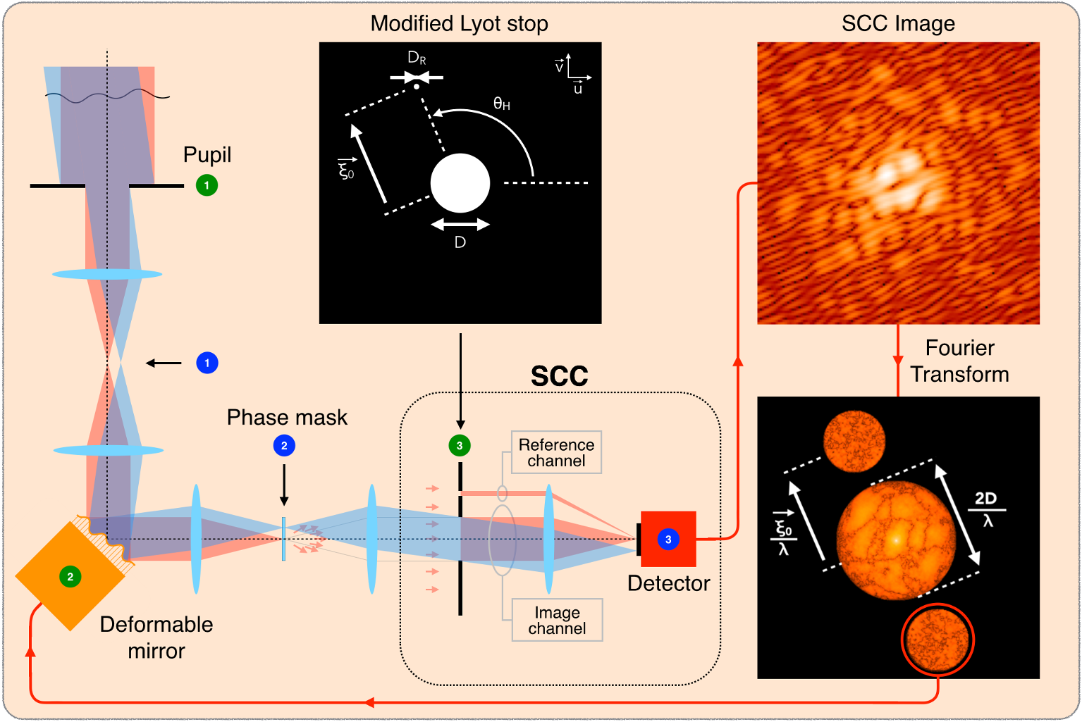
The stellar beam (red) hits a deformable mirror. Then, it is focused onto a coronagraphic focal plane mask that scatters light in the Lyot stop plane outside the geometrical pupil. A Lyot diaphragm stops the stellar light before it reaches the detector. If optical aberrations exist, part of the starlight is scattered inside the Lyot diaphragm and reaches the detector forming speckles that mimic an exoplanet image. The SCC consists on adding a small hole in the Lyot stop (top image) to create a reference beam that interferes with the image channel and spatially modulates the stellar speckles in the science image recorded by the detector (top right). The SCC is then doing classical off-axis holography and the lateral peak in the Fourier transform of that SCC image (bottom right) provides a direct estimation of the electric field in the science image. An interaction matrix is then recorded and it is possible to control a deformable mirror to minimize for the speckle intensity enhancing the contrast in the science image (Mazoyer et al., 2013, 2014). If an exoplanet (blue beam) orbits the targeted star so that its image is not centered onto the focal plane mask, none of its light goes through the reference channel and its image is not fringed.
3 Implementation in the stellar double coronagraph instrument
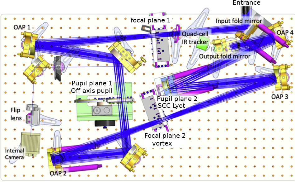
The stellar double coronagraph (SDC) instrument (figure 2, Mawet et al., 2014; Bottom et al., 2016b) is installed at the primary focus of the Hale 200 inch telescope at Palomar. It is fed by the PALM-3000 adaptive optics system (Bouchez et al., 2008). It was designed to cancel the stellar light using two vortex coronagraphs in cascade (Mawet et al., 2011). After entering the SDC bench, the beam goes through Focal plane 1, Pupil plane 1, Focal plane 2, Pupil plane 2 and then, it is injected in the PHARO system (Hayward et al., 2001).
The SCC has already been associated with numerous phase mask coronagraphs (Baudoz et al., 2018a) reaching very high contrast levels down to in space-like conditions (Baudoz et al., 2018b). And, as described in section 2, implementing the SCC is as simple as adding a small hole in the Lyot stop. This hole diameter is times smaller than the science beam diameter and it is set at more than from the center of the science beam. Hence, the optics after the Lyot stop must be twice the science beam so that both the science and the reference channels can propagate. Such a constraint is not a problem when designing a new instrument. However, it forbids the implementation of the SCC in most of the existing coronagraphic instruments because the optics after the Lyot stop are usually a few percents larger than the science beam only.
To overcome this limitation and implement the SCC in the SDC instrument, we put no optics in focal plane 1 (figure 2). Doing so, the Hale pupil is reimaged in pupil plane 1 (figure 3).
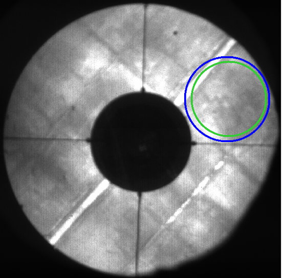
There, we add a diaphragm (represented by the blue circle) to create a 1.5m off-axis pupil from the full 5m obscured pupil. Then, we use the vortex phase mask of charge 2 in focal plane 2. And in pupil plane 2, we set up a reflective modified Lyot stop. The on-axis diaphragm stops the stellar light that is scattered by the vortex mask outside the geometrical pupil (classical coronagraphic Lyot stop in figure 4). The Lyot stop diameter is 88 % of the off-axis pupil diameter to remove the light scattered near the border of the geometrical pupil.
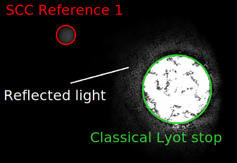
The SCC reference hole encircled in red in the figure has a diameter times smaller than the Lyot stop. As explained in Mazoyer et al. (2013), the light of the reference beam mainly spreads in an Airy pattern with a radius of in the coronagraphic image. Speckles are thus fringed up to from the optical axis. Therefore, the smaller the larger the field-of-view that can be corrected from speckles. However, the larger the fainter the intensity of the reference beam in the coronagraphic image and the fainter the fringe visibility. A trade-off has to be chosen between the fringe visibility and the size of the corrected field-of-view. In the case of the SDC, there was large aberrations meaning bright speckles during our run. We had to use so that speckles close to the optical axis were correctly fringed. We could then minimize the speckle intensity within from the optical axis. In order to enlarge the region of correction, we would have reduced the size of the reference hole (increasing ) but we did not due to lack of time.
In figure 4, all but the Lyot stop and the reference disks should be dark as the Lyot mask should stop the star light. However, the mask is not perfectly black and reflected light is detected close to the Lyot stop.
4 NCPA correction procedure
4.1 MGS algorithm limitation
At the Hale telescope, the current procedure used to minimize NCPA before the observations is based on a modified Gertzberg–Saxton (MGS) algorithm (Burruss et al., 2010). This technique estimates and minimizes the phase aberrations recording a set of out-of-focus non-coronagraphic images. The estimated aberrations include aberrations upstream and downstream the coronagraphic focal plane mask, and they are both compensated by a deformable mirror that is upstream the mask. In the focal plane where the coronagraphic mask is, the aberrations are thus overcorrected. And, after an MGS minimization of NCPA, part of the stellar light leaks through the coronagraph and induces stellar speckles in the science image (see section 5).
4.2 SCC procedure
To optimize the minimization of the speckle intensity in the science images, we used the SCC implemented in the SDC (section 3) in closed-loop controlling the Xinetics deformable mirror of the PALM-3000. As the SCC reference hole that we used is times smaller than the Lyot diaphragm, the visibility of the SCC fringes was detectable up to from the star in the science image (Mazoyer et al., 2013). Hence, we tried to minimize the speckle intensity up to . To correct at larger separations, one would need to use a smaller reference hole so that the reference intensity nulls further away.
One iteration of correction consists on recording one SCC coronagraphic science image, estimating the electric field associated with the stellar speckles from this image (section 2), and sending commands to the deformable mirror using the control matrix. The control matrix is the pseudo-inverse of the interaction matrix that we recorded using the internal source of the SDC instrument. To record this matrix, we used a truncated Fourier basis (Mazoyer et al., 2014) composed of all sine and cosine functions in the pupil plane that induce speckles below in the science image. One row of the interaction matrix is the estimated electric field in the science image when applying one function of our basis. To apply the sine/cosine phase functions, we modified the voltages of the deformable mirror. Recording this matrix with the Pharo detector was taking about minutes. Once this calibration was done, we could close the SCC correction loop to minimize the NCPA. Note that we assume small aberrations when recording the interaction matrix. As a consequence several iterations of correction are needed to minimize the speckle intensity.
5 Internal source
5.1 Performance
We were granted two nights at the Hale telescope on the Stellar Double Coronagraph (program 3660111https://reservations.palomar.caltech.edu/observing_schedule/abstract/3660). During daytime on the 25th of July 2018, we first minimized the NCPA in the SDC instrument using the MGS algorithm using the Br- filter (m and m, Hayward et al., 2001) and the internal source. NCPA were reduced but speckles were still present in the MGS coronagraphic image (left-hand panel in figure 5) because the MGS solution over-corrects the aberrations upstream the coronagraph focal plane mask as explained in section 4.1.
We then used the SCC to optimize the speckle minimization. We started from the MGS image (left-hand panel in figure 5) in which the SCC fringes are detected (from bottom left to top right). We estimated and corrected the aberrations up to around the optical axis. After three iterations, the speckle intensity inside the control area was efficiently reduced as showed on the right-hand panel in figure 5. The four satellite speckles are also present in the MGS image. They are between and and then, outside the corrected area. That is why they are not corrected in the SCC image.
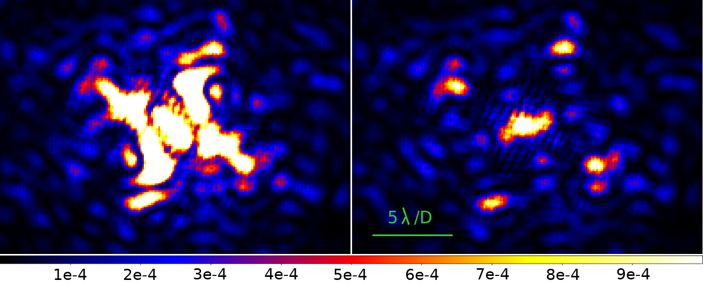
The detection limit for the MGS and the SCC calibrated images are plotted in figure 6.
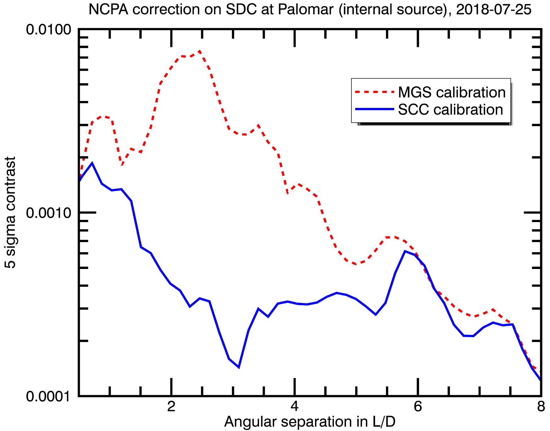
The detection limit is the azimuthal standard deviation of the intensity calculated in annuli of width and centered on the optical axis (i.e. the star image). The self-coherent camera improves the detection limit in the coronagraphic image by a factor between and between and . Such a result demonstrates the efficiency of the SCC very close to the optical axis where many exoplanets are to be discovered and where other techniques like angular and spectral differential imaging cannot calibrate the speckles (Marois et al., 2006; Racine et al., 1999).
5.2 Comparison with other techniques
Other techniques like reference differential imaging (Ruane et al., 2019) can partially calibrate the speckles close to the optical axis. They are however limited by speckles with lifetime shorter than few minutes (the speckle pattern then changes between the science target and the reference star). Other techniques can do focal plane wavefront sensing and correction (Martinache et al., 2014; Bottom et al., 2016a; Cady et al., 2013; Matthews et al., 2017; Bottom et al., 2017). Most of them use a temporal modulation of the speckle intensity and they cannot calibrate the speckles with lifetime shorter than the time needed for calibration (usually 4 to 5 images, meaning few minutes for a typical star magnitude).
5.3 Current limitation at Palomar
The contrast level reached in the SDC images (a few ) is quite moderate when compared to results obtained in laboratory (down to , Baudoz et al., 2018b). Close to the optical axis, the performance is set by the SDC vortex phase mask, the reflected light by the Lyot stop (see the end of section 3), and the jitter stability during the exposure that is s at minimum (plus s of overhead). We note however that the contrast we obtained in section 5.1 () is better than the one previously reached using the same 1.5m off-axis configuration ( to in Serabyn et al., 2010).
Further away from the optical axis, we believe that the performance can be improved in the current SDC instrument reducing the reflected light by the Lyot stop and optimizing the SCC speckle calibration but we had a limited amount of time at the telescope. However, improving the performance in SDC images does not mean reaching contrast levels. Such a performance is possible using a coronagraph that reaches contrast level of a few on the optical axis in a system that remains stable during the speckle calibration (gravity and thermal flexures inducing a jitter smaller than ). This would be possible using a faster detector than Pharo whose highest rate is about Hz.
6 Performance on sky
During our stay at the Palomar Observatory, the quad-cell infrared tracker that is used to stabilize the star image on the center of the vortex phase mask (i.e. control of the jitter, Bottom et al., 2016b) was not in service. Therefore, it was not possible to close the SCC loop on sky. Moreover, even if the quad-cell tracker was used, a faster detector than Pharo would be a key point to control the speckles before they evolve because of gravity or thermal flexures.
As we could not close the loop on sky, we used another approach. On the 25th of July 2018, we minimized the speckle intensity on internal source during daytime using the MGS algorithm and the SCC technique. Between h and h later, we opened the telescope and pointed Vega with a seeing of arcsec. We recorded sequences of images in Br with the beam aligned on the vortex coronagraph.
During the first sequence, we applied the MGS calibration described in section 5. We recorded exposures of s. The average of the coronagraphic images is showed on the left-hand panel in Fig. 7. The image is very similar to the one measured with the internal source except close to the center. This difference is due to uncorrected jitter when on-sky.
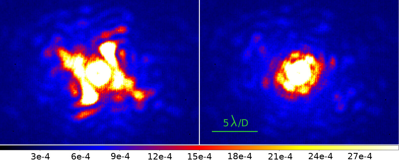
During the second sequence, we applied the SCC solution obtained with the internal source and we recorded exposures of s. The averaged image is showed on the right-hand panel in Fig. 7. As with the internal source, the quality of the image is clearly improved with respect to the MGS solution. Speckles are suppressed from the image. This is confirmed when plotting the detection limit (Fig. 8).
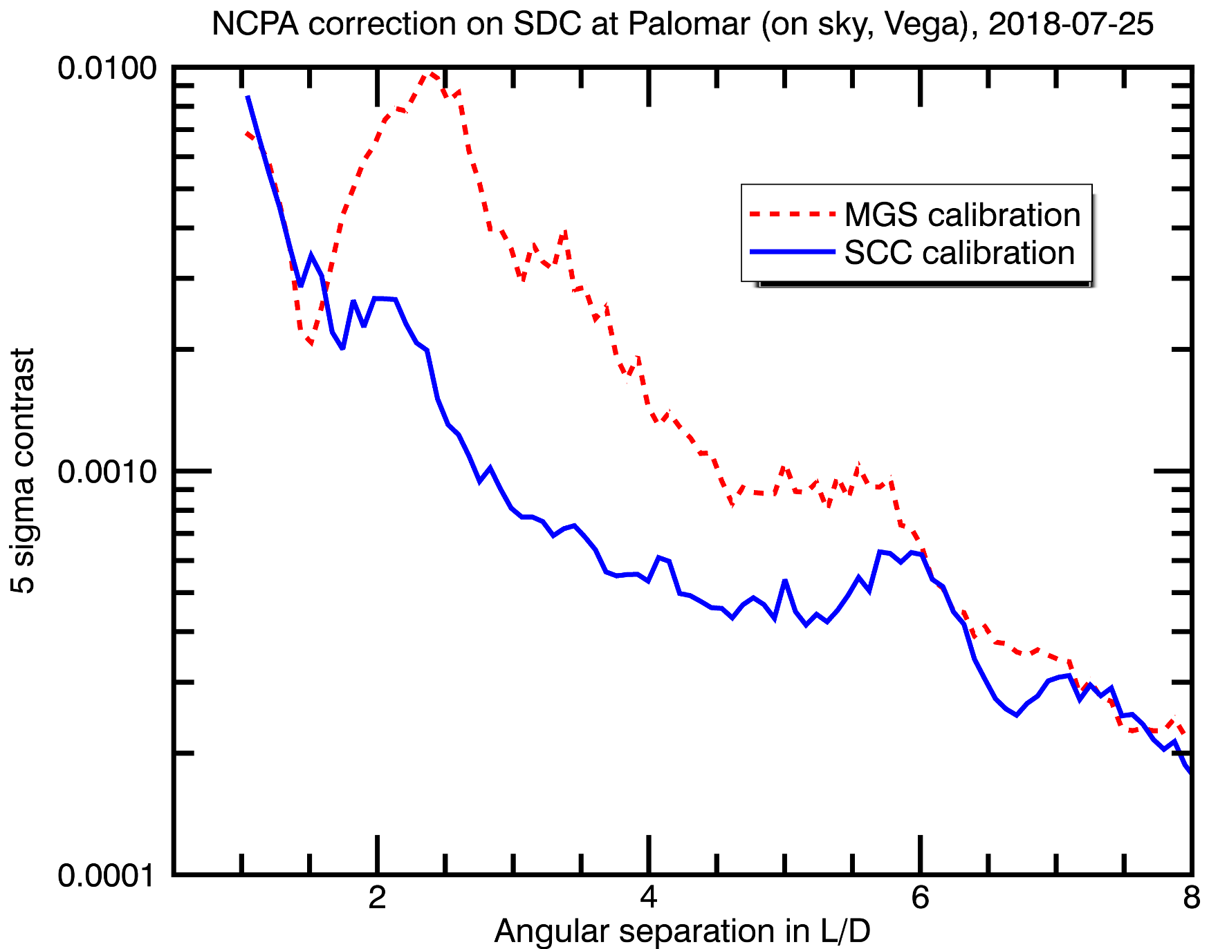
Between and , the detection limit is times better after SCC calibration than after MGS calibration. The difference with the image obtained on internal source (section 5) are the starlight leakage close the star center due to uncorrected jitter, a smooth halo created by averaging turbulence speckles, and residual speckles above this halo up to . The latter can be induced by uncorrected static aberrations due to telescope aberrations that were not calibrated using the internal source.
7 Conclusion
To improve exoplanet imaging instruments, a crucial point is to actively compensate for the non-common path aberrations (NCPA) between the classical adaptive system channel and the science coronagraphic image. The use of a focal plane wavefront sensor is optimal to estimate the electric field of the stellar speckles from the coronagraphic image. Such a sensor is the self-coherent camera (SCC) that spatially modulates the speckle intensity. To implement the SCC on the existing stellar double coronagraph at the Palomar telescope, we added a small off-axis hole in the Lyot stop of the vortex coronagraph.
Using the SCC, we improve the detection limit between and by a factor of to in the laboratory using the internal source. We then tested on-sky the quality of the internal calibration. We observed Vega and showed that the SCC calibration was times better between and when compared to the Palomar standard calibration used for NCPA minimization. The loss of performance of the SCC calibration between on-sky and on internal source may come from residual unaveraged aberrations in long but not infinite exposures. Further telescope time is needed to investigate this issue.
To conclude, we demonstrated the capacity of the self-coherent camera to calibrate NCPA in an existing instrument. This first demonstration was made using a narrow band filter but implementation of the SCC in broadband is possible using several SCC reference holes as explained in Delorme et al. (2016). The results related in this paper also highlight two interests of the SCC. First, the SCC can minimize the speckle intensity in the field of view especially the ones that are very close to the star where many exoplanets are to be discovered. Then, even if the SCC requires a 3-4 pixel sampling on the science detector instead of for other focal plane wavefront sensors, the SCC has a efficiency with science time as each image can be used for both science and NCPA minimization.
Acknowledgements.
The authors thank the Région Île-de-France and the Science Council of the Paris Observatory that supported this work.References
- Baudoz et al. (2006) Baudoz, P., Boccaletti, A., Baudrand, J., & Rouan, D. 2006, in IAU Colloq. 200: Direct Imaging of Exoplanets: Science Techniques, ed. C. Aime & F. Vakili, 553–558
- Baudoz et al. (2018a) Baudoz, P., Galicher, R., Patru, F., Dupuis, O., & Thijs, S. 2018a, arXiv e-prints
- Baudoz et al. (2018b) Baudoz, P., Galicher, R., Potier, A., et al. 2018b, in Society of Photo-Optical Instrumentation Engineers (SPIE) Conference Series, Vol. 10706, Advances in Optical and Mechanical Technologies for Telescopes and Instrumentation III, 107062O
- Baudoz et al. (2010) Baudoz, P., Mas, M., Galicher, R., & Rousset, G. 2010, in Society of Photo-Optical Instrumentation Engineers (SPIE) Conference Series, Vol. 7736, Society of Photo-Optical Instrumentation Engineers (SPIE) Conference Series
- Baudoz et al. (2012) Baudoz, P., Mazoyer, J., Mas, M., Galicher, R., & Rousset, G. 2012, in Society of Photo-Optical Instrumentation Engineers (SPIE) Conference Series, Vol. 8446, Society of Photo-Optical Instrumentation Engineers (SPIE) Conference Series
- Bordé & Traub (2006) Bordé, P. J. & Traub, W. A. 2006, Astrophysical Journal, 638, 488
- Bottom et al. (2016a) Bottom, M., Femenia, B., Huby, E., et al. 2016a, in Proceedings of the SPIE, Vol. 9909, Adaptive Optics Systems V, 990955
- Bottom et al. (2016b) Bottom, M., Shelton, J. C., Wallace, J. K., et al. 2016b, Publication of the Astronomical Society of Pacific, 128, 075003
- Bottom et al. (2017) Bottom, M., Wallace, J. K., Bartos, R. D., Shelton, J. C., & Serabyn, E. 2017, Monthly Notices of the Royal Astronomical Society, 464, 2937
- Bouchez et al. (2008) Bouchez, A. H., Dekany, R. G., Angione, J. R., et al. 2008, in Society of Photo-Optical Instrumentation Engineers (SPIE) Conference Series, Vol. 7015, Adaptive Optics Systems, 70150Z
- Burruss et al. (2010) Burruss, R. S., Serabyn, E., Mawet, D. P., et al. 2010, in Proceedings of the SPIE, Vol. 7736, Adaptive Optics Systems II, 77365X
- Cady et al. (2013) Cady, E., Baranec, C., Beichman, C., et al. 2013, in Proceedings of the SPIE, Vol. 8864, Techniques and Instrumentation for Detection of Exoplanets VI, 88640K
- Delorme et al. (2016) Delorme, J. R., Galicher, R., Baudoz, P., et al. 2016, Astronomy and Astrophysics, 588, A136
- Galicher et al. (2014) Galicher, R., Baudoz, P., Delorme, J. R., et al. 2014, in Society of Photo-Optical Instrumentation Engineers (SPIE) Conference Series, Vol. 9143, Space Telescopes and Instrumentation 2014: Optical, Infrared, and Millimeter Wave, 91435A
- Galicher et al. (2008) Galicher, R., Baudoz, P., & Rousset, G. 2008, Astronomy and Astrophysics, 488, L9
- Galicher et al. (2010) Galicher, R., Baudoz, P., Rousset, G., Totems, J., & Mas, M. 2010, Astronomy and Astrophysics, 509, A31+
- Give’on et al. (2007) Give’on, A., Kern, B., Shaklan, S., Moody, D. C., & Pueyo, L. 2007, in Proceedings of the SPIE, Vol. 6691, Astronomical Adaptive Optics Systems and Applications III, 66910A
- Give’on et al. (2011) Give’on, A., Kern, B. D., & Shaklan, S. 2011, in Proceedings of the SPIE, Vol. 8151, Techniques and Instrumentation for Detection of Exoplanets V, 815110
- Hayward et al. (2001) Hayward, T. L., Brandl, B., Pirger, B., et al. 2001, The Publications of the Astronomical Society of the Pacific, 113, 105
- Lawson et al. (2013) Lawson, P. R., Belikov, R., Cash, W., et al. 2013, in Proc. SPIE, Vol. 8864, Techniques and Instrumentation for Detection of Exoplanets VI, 88641F
- Macintosh et al. (2014) Macintosh, B., Graham, J. R., Ingraham, P., et al. 2014, Proceedings of the National Academy of Science, 111, 12661
- Marois et al. (2006) Marois, C., Lafrenière, D., Doyon, R., Macintosh, B., & Nadeau, D. 2006, The Astrophysical Journal, 641, 556
- Martinache et al. (2014) Martinache, F., Guyon, O., Jovanovic, N., et al. 2014, in Proceedings of the SPIE, Vol. 9148, Adaptive Optics Systems IV, 914821
- Matthews et al. (2017) Matthews, C. T., Crepp, J. R., Vasisht, G., & Cady, E. 2017, Journal of Astronomical Telescopes, Instruments, and Systems, 3, 045001
- Mawet et al. (2011) Mawet, D., Serabyn, E., Wallace, J. K., & Pueyo, L. 2011, ArXiv e-prints
- Mawet et al. (2014) Mawet, D., Shelton, C., Wallace, J., et al. 2014, in Proceedings of the SPIE, Vol. 9143, Space Telescopes and Instrumentation 2014: Optical, Infrared, and Millimeter Wave, 91432T
- Mazoyer et al. (2013) Mazoyer, J., Baudoz, P., Galicher, R., Mas, M., & Rousset, G. 2013, Astronomy and Astrophysics, 557, A9
- Mazoyer et al. (2014) Mazoyer, J., Baudoz, P., Galicher, R., & Rousset, G. 2014, Astronomy and Astrophysics, 564, L1
- Racine et al. (1999) Racine, R., Walker, G. A. H., Nadeau, D., Doyon, R., & Marois, C. 1999, Publications of the Astronomical Society of the Pacific, 111, 587
- Ruane et al. (2019) Ruane, G., Ngo, H., Mawet, D., et al. 2019, The Astronomical Journal, 157, 118
- Serabyn et al. (2010) Serabyn, E., Mawet, D., & Burruss, R. 2010, Nature, 464, 1018
- Snik et al. (2018) Snik, F., Absil, O., Baudoz, P., et al. 2018, in Society of Photo-Optical Instrumentation Engineers (SPIE) Conference Series, Vol. 10706, Advances in Optical and Mechanical Technologies for Telescopes and Instrumentation III, 107062L