Magnetic chirality controlled by the interlayer exchange interaction
Abstract
Chiral magnetism, wherein there is a preferred sense of rotation of the magnetization, has become a key aspect for future spintronic applications. It determines the chiral nature of magnetic textures, such as skyrmions, domain walls or spin spirals, and a specific magnetic chirality is often required for spintronic applications. Current research focuses on identifying and controlling the interactions that define the magnetic chirality. The influence of the interfacial Dzyaloshinskii-Moriya interaction (iDMI) and, recently, the dipolar interactions have previously been reported. Here, we experimentally demonstrate that an indirect interlayer exchange interaction can be used as an additional tool to effectively manipulate the magnetic chirality. We image the chirality of magnetic domain walls in a coupled bilayer system using scanning electron microscopy with polarization analysis (SEMPA). Upon increasing the interlayer exchange coupling, we induce a transition of the magnetic chirality from clockwise rotating Néel walls to degenerate Bloch-Néel domain walls and we confirm our findings with micromagnetic simulations. In multi-layered systems relevant for skyrmion research a uniform magnetic chirality across the magnetic layers is often desired. Additional simulations show that this can be achieved for reduced iDMI values when exploiting the interlayer exchange interaction. This work opens up new ways to control and tailor the magnetic chirality by the interlayer exchange interaction.
Magnetic chirality corresponds to a preferred sense of rotation of the magnetization and understanding this chirality has become of great importance for new spintronic applications Fert et al. (2017); Everschor-Sitte et al. (2018); Nagaosa and Tokura (2013). These applications rely on the chiral nature of magnetic textures, like skyrmions or domain walls. In future magnetic memory devices, for instance the racetrack memory Fert et al. (2013), a controlled displacement of skyrmions or domain walls is of utmost importance for a reliable operation and a key requisite for this is a uniform magnetic chirality of the magnetic textures Thiaville et al. (2012); Emori et al. (2013); Ryu et al. (2013); Sampaio et al. (2013); Woo et al. (2016). Current research focuses on identifying and controlling the interactions that define the magnetic chirality. Understanding the underlying mechanisms will allow one to tailor the magnetic chirality Hrabec et al. (2017) for spintronic applications.
The most promising interaction that allows for the control of the magnetic chirality is the interfacial Dzyaloshinskii-Moriya interaction (iDMI), which has been studied extensively in the past years in magnetic thin films Han et al. (2016); Yang et al. (2018); Ma et al. (2018); Kloodt-Twesten et al. (2019). This interaction is an anti-symmetric exchange interaction and originates from a broken symmetry at the interface of a ferromagnet and heavy metal Bogdanov and Rößler (2001); Bode et al. (2007); Heide et al. (2008). The strength and sign of the iDMI depends on the specific material combination at an interface and the iDMI energetically favors either a clockwise (CW) or counterclockwise (CCW) rotation of the magnetization. This allows for the stabilization of magnetic textures, like skyrmions, Néel domain walls or spin spirals, with a uniform magnetic chirality Fert et al. (2017); Bode et al. (2007).
Very recently, it was recognized that dipolar fields also influence the magnetic chirality Lemesh and Beach (2018); Legrand et al. (2018a, b); Fallon et al. (2019); Dovzhenko et al. (2018); Lucassen et al. (2019). Although the effects of the dipolar interaction were already known for a long time Hubert and Schäfer (1998); Malozemoff and Slonczewski (1979); Kamberskỳ (1995); Labrune and Belliard (1999); Tekielak et al. (2011), their impact on magnetic thin-film systems hosting an iDMI was only recently observed when stacking several magnetic thin-films on top of each other. These magnetic multi-layers are commonly used to stabilize skyrmions at room temperature Moreau-Luchaire et al. (2016); Woo et al. (2016) and the increased magnetic volume leads to stronger dipolar fields. As a result, the dipolar field emitted from out-of-plane magnetized domains can influence the in-plane magnetization, which results in a non-uniform magnetic chirality across the magnetic multi-layers. Various models Lemesh and Beach (2018); Legrand et al. (2018a, b) and first experiments Dovzhenko et al. (2018) show that this behavior can be generalized and has a profound impact on many magnetic textures such as skyrmions and derived entities. For most spintronic applications the stabilization of a uniform magnetic chirality across a multi-layered system is desired, Legrand et al. (2018b); Lemesh and Beach (2018) which can be achieved by implementing a strong iDMI to overcome the dipolar interaction. Generating a strong iDMI is not always achievable, however, and severely constrains the design of the multi-layered system.
In this article, we demonstrate an alternative approach to control the magnetic chirality utilizing the effect of an indirect interlayer exchange interaction Stiles (1999); Bruno (1995); Hellwig et al. (2007); Chen et al. (2015); Nandy et al. (2016), namely the conventional Ruderman–Kittel–Kasuya–Yosida (RKKY)111The recently discovered asymmetric exchange component of the RKKY interaction is not present in this work Fernández-Pacheco et al. (2019); Han et al. (2019). interaction Parkin (1991); Luo et al. (1998); Bruno (1995). First, we determine the influence of the ferromagnetic RKKY interaction on the magnetic chirality by imaging the domain wall magnetization in a bilayer system with negligible iDMI using scanning electron microscopy with polarization analysis (SEMPA) Oepen and Hopster (2005); Unguris (2001); Frömter et al. (2011); Corredor et al. (2017). In the absence of the RKKY interaction the dipolar fields cause a non-uniform magnetic chirality in the bilayer system, and this results in the formation of CW Néel walls in the top magnetic layer and CCW Néel walls in the bottom magnetic layer as is schematically depicted in Fig. 1a. Upon increasing the ferromagnetic RKKY coupling, the magnetization in the domain walls asymptotically rotates towards non-chiral Bloch walls. In the second part we investigate a multi-layered system including iDMI typically used for skyrmion research with the help of micromagnetic simulations. We explicitly show that the necessary iDMI values to obtain a uniform magnetic chirality can be reduced by 30% in the presence of a strong ferromagnetic RKKY interaction. Utilizing the RKKY interaction therefore opens up new ways to tune and control the chirality of magnetic textures on a layer-by-layer basis.
Before we show our dedicated sample design and illustrate the obtained experimental results, we would like to first address the basic physical principles of how the dipolar fields and in particular the ferromagnetic RKKY influence the magnetic chirality in the absence of an iDMI. We concentrate on an elementary model consisting of two magnetic CoNi layers RKKY-coupled via an Ir spacer layer as depicted in Fig. 1a, which mimics the experimental situation. Both layers exhibit a perpendicular magnetic anisotropy and the up and down domains (white and black areas, respectively) of the magnetic bilayer generate dipolar fields as indicated by the grey dashed line. The in-plane magnetization direction inside the domain walls aligns with the dipolar fields as depicted by the arrows in the green and pink area and this leads to the formation of a CW Néel wall in the top magnetic layer and a CCW Néel wall in the bottom magnetic layer. By coupling the magnetic layers ferromagnetically (dashed blue line) this anti-parallel alignment of the magnetization in the domain wall can be counteracted, resulting in the stabilization of degenerate Bloch walls pointing either into the paper (as indicated by the blue arrows) or out of the paper (not shown).
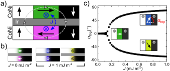
We confirm the validity of this intuitive picture using MuMax3 Vansteenkiste et al. (2014); Clercq et al. (2017) micromagnetic simulations, with the simulation conditions specified in supplementary SI. On the left side of Fig. 1b the result in the absence of a ferromagnetic RKKY coupling ( ) is depicted and the formation of a CW/CCW Néel wall in the top/bottom magnetic layer is found, respectively, as expected from the dipolar interaction. Introducing a ferromagnetic RKKY coupling ( ) leads to the formation of two energetically degenerate Bloch walls, as depicted on the right side of Fig. 1b, where the in-plane magnetization direction of both magnetic layers points either into the paper (blue area) or out of the paper (yellow area). We therefore find, that a uniform magnetization profile across the magnetic layers in a bilayer system can be achieved due to the presence of a ferromagnetic RKKY interaction. A preferred chirality is not present, however, since two kinds of Bloch domain walls can be stabilized. In Fig. 1c we study the transition between Néel and Bloch walls as a function of in more detail. Here, we focus on the domain wall formation in the top magnetic layer and the angle describes the in-plane magnetization direction of the domain wall as depicted schematically in the top right inset. We find that for (see left inset) and asymptotically approaches the formation of Bloch walls () for large . For intermediate values of degenerate Bloch-Néel domain walls are formed and this is schematically depicted in the insets on the right side for a value of . The micromagnetic results indicate that the ferromagnetic RKKY interaction influences the magnetic chirality and that the strength of the interaction determines the in-plane magnetization direction of the domain walls.
In the following we experimentally measure this influence by imaging the domain wall chirality in a bilayer system with SEMPA for different RKKY coupling strengths. Here, we map the magnetization profile of specifically the top magnetic layer, due to the high surface sensitivity of SEMPA. From literature it is known that Iridium mediates a strong RKKY interaction that alternates between an antiferromagnetic (AF, ) and ferromagnetic (FM, ) coupling as a function of thickness with a damped sinusoidal behavior Stiles (1999); Parkin (1991); Luo et al. (1998); Bruno (1995). We therefore grew a sample with the following composition: //Ta(3)/Pt(3)/[Co(0.6)/Ni(0.35)]Co(0.2)/Ir() /[Co(0.6)/Ni(0.35)] (thicknesses in parentheses in nm), where the Ir thickness is wedged from , providing access to both the ferromagnetic and antiferromagnetic coupling regime of the RKKY interaction (see Methods for more details).
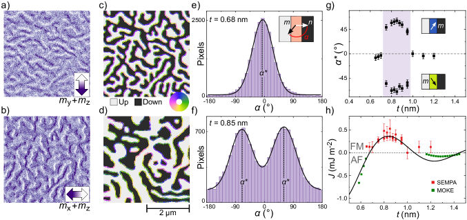
In Fig. 2a and b SEMPA images of the top magnetic layer are depicted at an Ir thickness of . The images were measured simultaneously and show the same area. Fig. 2a displays the magnetization contrast and Fig. 2b the magnetization contrast, as indicated by the arrows in the bottom right corner. In both images a slight out-of-plane contrast is also visible (see Methods), where the lighter areas correspond to up domains and the darker areas to down domains. The domains are framed by dark or light bands, which correspond to the in-plane component of the magnetization in the domain wall. The combined information of the SEMPA images is depicted in the composite image of Fig. 2c using a procedure described elsewhere Lucassen et al. (2019). Here, the out-of-plane contrast is indicated by the white and dark areas (up and down, respectively), and the in-plane magnetization direction in the domain wall is indicated by the color wheel. From the composite image we find that the domain walls on the left side of an up domain are pink, which is equivalent to the magnetization pointing towards the left, whereas the magnetization on the right side of an up domain points towards the right, illustrated by the green color. This indicates that the magnetization in the domain wall always points from an up domain towards a down domain and reveals the presence of CW Néel walls. We can investigate this more thoroughly by defining an angle , which is the difference between the domain wall normal and the magnetization direction , as depicted in the inset of Fig. 2e. Assigning this angle to every pixel in the domain wall results in the histogram shown in Fig. 2e. Around a peak in the histogram is observed that corresponds to the formation of CW Néel walls. The histogram is fitted with a Gaussian curve that models the underlying statistics of the individual pixels Lucassen et al. (2019) and allows one to extract the peak position . For an Ir thickness of the same procedure results in the composite image shown in Fig. 2d and the corresponding histogram is depicted in Fig. 2f. In the histogram two distinct peaks are observed and their position is extracted with a double Gaussian fit giving and . The two types of domain walls that are stabilized in Fig. 2d,f are neither CW Néel walls () nor Bloch walls (), but show rather an intermediate Bloch-Néel texture as is schematically depicted in the insets of Fig. 1c. Additional measurements for different Ir thicknesses can be found in supplementary SII.
The extracted is plotted as a function of Ir thickness in Fig. 2g. CW Néel walls are formed for and and the two degenerate Bloch-Néel walls are present for intermediate Ir thicknesses in the purple-shaded area. Within this shaded area an increase in is observed for increasing , until a maximum is reached at , whereafter decreases again. According to the findings presented in Fig. 1c, the CW Néel walls are stabilized by the dipolar interaction. The formation of the degenerate Bloch-Néel walls in the purple-shaded area can then be explained by the interplay between the dipolar interaction and ferromagnetic RKKY interaction. Since scales with , we find the expected increase and decrease of the ferromagnetic RKKY coupling as a function of the Ir thickness.
To further substantiate that the interlayer exchange interaction is the dominant mechanism that stabilizes the degenerate Bloch-Néel walls, we study the expected oscillatory behavior of the RKKY interaction in more detail. Therefore, we combine the information on the coupling strength in both the ferromagnetic and antiferromagnetic region as a function of the Ir layer thickness and this is plotted in Fig. 2h. The data in the ferromagnetic region is plotted in red and obtained via the SEMPA measurements discussed previously, where the angle from Fig. 2g is converted to a coupling strength using the micromagnetic simulations presented in Fig. 1c. Information on the coupling strength in the antiferromagnetic RKKY region can be obtained from the switching fields in the antiferromagnetic hysteresis loops measured by the magneto-optical Kerr effect (MOKE), as is explained in more detail in supplementary SIII. In Fig. 2h the coupling values in the antiferromagnetic region are plotted in green. When we combine both data sets we clearly observe the oscillatory behavior of the RKKY coupling as a function of the Ir thickness and the data is fitted with the theoretically predicted RKKY behavior Bruno (1995) (solid black curve). The theory describes the periodic behavior well and a maximum ferromagnetic coupling of approximately is obtained at . Both the extracted period of the oscillation as well as the RKKY coupling strength are in agreement with values found in literature Karayev et al. (2019); Parkin (1991); Luo et al. (1998).
So far, we have seen experimentally and from micromagnetic simulations that in the absence of an iDMI the RKKY interaction influences the magnetic chirality induced by the dipolar interaction. Moreover, the simulations of Fig. 1b indicate that the difference between the in-plane magnetization directions of the domain walls across the bilayer system is reduced due to the ferromagnetic RKKY coupling. For a strong coupling almost identical magnetic textures are stabilized in the top and bottom magnetic layer. A uniform magnetic chirality can not be obtained by the ferromagnetic RKKY interaction alone, however, due to the degeneracy of the Bloch-(Néel) walls. Adding an iDMI can lift this degeneracy and a uniform chirality across the magnetic layers can be achieved.
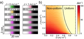
In the following we examine the necessary conditions to obtain a uniform magnetic chirality across the magnetic multi-layers, when the dipolar interaction, RKKY interaction and iDMI are present. We study this with micromagnetic simulations in a multi-layered system typically hosting chiral magnetic textures like skyrmions. The investigated multi-layered stack consists of 6 repeats with alternating magnetic and spacer layers of (details of the simulations and the dependence on saturation magnetization and effective anisotropy values can be found in the supplementary SI and SIV). In Fig. 3a the magnetic textures obtained for two RKKY strengths are depicted with an iDMI of . In the left image and a non-uniform magnetization texture is observed across the magnetic layers. The bottom layers form CCW Néel walls, favored by the positive , but the iDMI is not strong enough to counteract the dipolar interaction. This results in the formation of a Bloch wall and CW Néel in the top two layers. We define the uniformity of the chirality in the multi-layered system by subtracting the values from the bottom and top magnetic layer and this results in for the case of . In the right image of Fig. 3a and an approximately uniform chirality in all the magnetic layers is achieved with . In Fig. 3b is plotted for a range of and values. Two regions are indicated where the chirality is either non-uniform () or uniform (). Without an RKKY interaction ( ) an iDMI value of at least is needed to stabilize a uniform chirality and this corresponds to the critical iDMI value of the system. Interestingly, this critical iDMI value can be reduced by approximately 30% when an RKKY interaction of is present, as can be seen from the transition line in Fig. 3b. In practice these and values can be achieved in magnetic multi-layers by optimizing the thicknesses and materials of the magnetic and non-magnetic spacer layer Parkin (1991); Han et al. (2016), which makes it possible to stabilize magnetic textures with a uniform chirality in a wider variety of multi-layered systems than previously assumed.
Finally, an additional effect of the interlayer exchange coupling on the magnetic texture becomes apparent when we compare the images of Fig. 2c and d. The average domain size grows as the ferromagnetic RKKY interaction increases and this is elaborated in more detail in supplementary SV. Although the influence of the iDMI is not considered yet, the findings suggest that the RKKY interaction might be used to control the size of magnetic domains and possibly even skyrmions.
To conclude, we have demonstrated that an interlayer exchange interaction influences the magnetic chirality. In a system where dipolar fields are present, the influence of the RKKY interaction manifests itself as a rotation of the magnetization in the top domain wall from a CW Néel to a degenerate Bloch-Néel wall. We confirm these findings by micromagnetic simulations. Furthermore, micromagnetic simulations predict that the RKKY interaction reduces the iDMI required to obtain a uniform magnetic chirality across a typical multi-layer system for skyrmion research. Making use of the well-known interlayer exchange interaction opens up new ways to tune and control the magnetic chirality in multi-layered systems for spintronic applications.
This work is part of the research programme of the Foundation for Fundamental Research on Matter (FOM), which is part of the Netherlands Organisation for Scientific Research (NWO). We acknowledge financial support by the DFG within SFB 668. R. A. D. also acknowledges the support of the European Research Council.
I Methods
The sample that is investigated consists of two magnetic CoNi layers coupled via an Ir spacer layer, with the following composition: //Ta(3)/Pt(3)/[Co(0.6)/Ni(0.35)]Co(0.2)/Ir() /[Co(0.6)/Ni(0.35)] (thicknesses in parentheses in nm). We wedged the Ir layer between to vary the strength of the RKKY coupling. The sample was grown on a Si substrate with a native oxide layer by DC sputter deposition. The base pressure of the system is and the Ar pressure during deposition was . The saturation magnetization and anisotropy values can be found in supplementary SI. We optimized the thickness composition of Co and Ni such that the sample shows a perpendicular magnetic anisotropy, but is close to the spin-reorientation transition. This ensures that the as-deposited sample is in a multi-domain state and can be imaged directly as we transfer the sample in-situ to the SEMPA setup. With SEMPA we can map the complete in-plane magnetization vector Oepen and Hopster (2005); Unguris (2001); Frömter et al. (2011). Additionally, we can distinguish up and down domains by tilting the sample stage, which results in a projection of the out-of-plane magnetization on the in-plane measurement axis Corredor et al. (2017); Frömter et al. (2008); Lucassen et al. (2017). The out-of-plane contrast in the image is well defined and adjustable by rotation of the sample stage. The out-of-plane contrast in depends strongly on the sample mounting. From the SEMPA measurements a composite image as depicted in Fig. 2c and d can be obtained and the method is described in Ref. Lucassen et al. (2019). This reference additionally shows that the widths of the histograms in Fig. 2e and f is mainly the result of Poisson noise in the electron counting Frömter et al. (2011) and errors in the extraction of the domain wall normal222Note that in reference Lucassen et al. (2019) the domain wall normal is rotated by compared to definition found in this article..
References
- Fert et al. (2017) A. Fert, N. Reyren, and V. Cros, Nat. Rev. Mat. 2, 17031 (2017).
- Everschor-Sitte et al. (2018) K. Everschor-Sitte, J. Masell, R. M. Reeve, and M. Kläui, J. Appl. Phys. 124, 240901 (2018).
- Nagaosa and Tokura (2013) N. Nagaosa and Y. Tokura, Nat. Nanotechnol. 8, 899 (2013).
- Fert et al. (2013) A. Fert, V. Cros, and J. Sampaio, Nat. Nanotechnol. 8, 152 (2013).
- Thiaville et al. (2012) A. Thiaville, S. Rohart, É. Jué, V. Cros, and A. Fert, EPL 100, 57002 (2012).
- Emori et al. (2013) S. Emori, U. Bauer, S.-M. Ahn, E. Martinez, and G. S. D. Beach, Nat. Mater. 12, 611 (2013).
- Ryu et al. (2013) K.-S. Ryu, L. Thomas, S.-H. Yang, and S. Parkin, Nat. Nanotechnol. 8, 527 (2013).
- Sampaio et al. (2013) J. Sampaio, V. Cros, S. Rohart, A. Thiaville, and A. Fert, Nat. Nanotechnol. 8, 839 (2013).
- Woo et al. (2016) S. Woo, K. Litzius, B. Krüger, M.-Y. Im, L. Caretta, K. Richter, M. Mann, A. Krone, R. M. Reeve, M. Weigand, P. Agrawal, I. Lemesh, M.-A. Mawass, P. Fischer, M. Kläui, and G. S. D. Beach, Nat. Mater. 15, 501 (2016).
- Hrabec et al. (2017) A. Hrabec, J. Sampaio, M. Belmeguenai, I. Gross, R. Weil, S. M. Chérif, A. Stashkevich, V. Jacques, A. Thiaville, and S. Rohart, Nat. Comm. 8, 15765 (2017).
- Han et al. (2016) D.-S. Han, N.-H. Kim, J.-S. Kim, Y. Yin, J.-W. Koo, J. Cho, S. Lee, M. Kläui, H. J. M. Swagten, B. Koopmans, and C.-Y. You, Nano Lett. 16, 4438 (2016).
- Yang et al. (2018) H. Yang, O. Boulle, V. Cros, A. Fert, and M. Chshiev, Sci. Rep. 8 (2018).
- Ma et al. (2018) X. Ma, G. Yu, C. Tang, X. Li, C. He, J. Shi, K. L. Wang, and X. Li, Phys. Rev. Lett. 120, 157204 (2018).
- Kloodt-Twesten et al. (2019) F. Kloodt-Twesten, S. Kuhrau, H. P. Oepen, and R. Frömter, Phys. Rev. B 100, 100402(R) (2019).
- Bogdanov and Rößler (2001) A. N. Bogdanov and U. K. Rößler, Phys. Rev. Lett. 87, 037203 (2001).
- Bode et al. (2007) M. Bode, M. Heide, K. von Bergmann, P. Ferriani, S. Heinze, G. Bihlmayer, A. Kubetzka, O. Pietzsch, S. Blügel, and R. Wiesendanger, Nature 447, 190 (2007).
- Heide et al. (2008) M. Heide, G. Bihlmayer, and S. Blügel, Phys. Rev. B 78, 140403 (2008).
- Lemesh and Beach (2018) I. Lemesh and G. S. D. Beach, Phys. Rev. B 98, 104402 (2018).
- Legrand et al. (2018a) W. Legrand, N. Ronceray, N. Reyren, D. Maccariello, V. Cros, and A. Fert, Phys. Rev. Appl. 10, 064042 (2018a).
- Legrand et al. (2018b) W. Legrand, J.-Y. Chauleau, D. Maccariello, N. Reyren, S. Collin, K. Bouzehouane, N. Jaouen, V. Cros, and A. Fert, Sci. Adv. 4 (2018b).
- Fallon et al. (2019) K. Fallon, S. McVitie, W. Legrand, F. Ajejas, D. Maccariello, S. Collin, V. Cros, and N. Reyren, arXiv e-prints , arXiv:1901.03652 (2019), arXiv:1901.03652 [cond-mat.mtrl-sci] .
- Dovzhenko et al. (2018) Y. Dovzhenko, F. Casola, S. Schlotter, T. X. Zhou, F. Büttner, R. L. Walsworth, G. S. D. Beach, and A. Yacoby, Nat. Comm. 9, 2712 (2018).
- Lucassen et al. (2019) J. Lucassen, M. J. Meijer, O. Kurnosikov, H. J. M. Swagten, B. Koopmans, R. Lavrijsen, F. Kloodt-Twesten, R. Frömter, and R. A. Duine, Phys. Rev. Lett. 123, 157201 (2019).
- Hubert and Schäfer (1998) A. Hubert and R. Schäfer, Magnetic Domains : the Analysis of Magnetic Microstructures, 1st ed. (Springer-Verlag Berlin Heidelberg, New York, 1998) pp. 240–241.
- Malozemoff and Slonczewski (1979) A. Malozemoff and J. Slonczewski, Magnetic domain walls in bubble materials, Applied solid state science: Supplement (Academic Press, New York, 1979).
- Kamberskỳ (1995) V. Kamberskỳ, J. Magn. Soc. Jpn. 19, S1_37 (1995).
- Labrune and Belliard (1999) M. Labrune and L. Belliard, Phys. Status Solidi A 174, 483 (1999).
- Tekielak et al. (2011) M. Tekielak, R. Gieniusz, M. Kisielewski, P. Mazalski, A. Maziewski, V. Zablotskii, F. Stobiecki, B. Szymański, and R. Schäfer, J. Appl. Phys. 110, 043924 (2011).
- Moreau-Luchaire et al. (2016) C. Moreau-Luchaire, C. Moutafis, N. Reyren, J. Sampaio, C. A. F. Vaz, N. Van Horne, K. Bouzehouane, K. Garcia, C. Deranlot, P. Warnicke, P. Wohlhüter, J.-M. George, M. Weigand, J. Raabe, V. Cros, and A. Fert, Nat. Nanotechnol. 11, 444 (2016).
- Stiles (1999) M. Stiles, J. Magn. Magn. Mater. 200, 322 (1999).
- Bruno (1995) P. Bruno, Phys. Rev. B 52, 411 (1995).
- Hellwig et al. (2007) O. Hellwig, A. Berger, J. B. Kortright, and E. E. Fullerton, J. Magn. Magn. Mater. 319, 13 (2007).
- Chen et al. (2015) G. Chen, A. Mascaraque, A. T. N’Diaye, and A. K. Schmid, Appl. Phys. Lett. 106, 242404 (2015).
- Nandy et al. (2016) A. K. Nandy, N. S. Kiselev, and S. Blügel, Phys. Rev. Lett. 116, 177202 (2016).
- Fernández-Pacheco et al. (2019) A. Fernández-Pacheco, E. Vedmedenko, F. Ummelen, R. Mansell, D. Petit, and R. P. Cowburn, Nat. Mater. , 1 (2019).
- Han et al. (2019) D.-S. Han, K. Lee, J.-P. Hanke, Y. Mokrousov, K.-W. Kim, W. Yoo, Y. L. van Hees, T.-W. Kim, R. Lavrijsen, C.-Y. You, et al., Nat. Mater. , 1 (2019).
- Parkin (1991) S. S. P. Parkin, Phys. Rev. Lett. 67, 3598 (1991).
- Luo et al. (1998) Y. Luo, M. Moske, and K. Samwer, EPL 42, 565 (1998).
- Oepen and Hopster (2005) H. Oepen and H. Hopster, “Sempa studies of thin films, structures, and exchange coupled layers,” in Magnetic Microscopy of Nanostructures, edited by H. Hopster and H. P. Oepen (Springer Berlin Heidelberg, Berlin, Heidelberg, 2005) pp. 137–167.
- Unguris (2001) J. Unguris, “Scanning electron microscopy with polarization analysis (sempa) and its applications,” in Experimental Methods in the Physical Sciences, Vol. 36, edited by M. De Graef and Y. Zhu (Academic Press, 2001) pp. 167–193.
- Frömter et al. (2011) R. Frömter, S. Hankemeier, H. P. Oepen, and J. Kirschner, Rev. Sci. Instrum. 82, 033704 (2011).
- Corredor et al. (2017) E. C. Corredor, S. Kuhrau, F. Kloodt-Twesten, R. Frömter, and H. P. Oepen, Phys. Rev. B 96, 060410(R) (2017).
- Vansteenkiste et al. (2014) A. Vansteenkiste, J. Leliaert, M. Dvornik, M. Helsen, F. Garcia-Sanchez, and B. Van Waeyenberge, AIP Adv. 4, 107133 (2014).
- Clercq et al. (2017) J. D. Clercq, J. Leliaert, and B. V. Waeyenberge, J. Phys. D: Appl. Phys. 50, 425002 (2017).
- Karayev et al. (2019) S. Karayev, P. D. Murray, D. Khadka, T. R. Thapaliya, K. Liu, and S. X. Huang, Phys. Rev. Mater. 3, 041401 (2019).
- Frömter et al. (2008) R. Frömter, H. Stillrich, C. Menk, and H. P. Oepen, Phys. Rev. Lett. 100, 207202 (2008).
- Lucassen et al. (2017) J. Lucassen, F. Kloodt-Twesten, R. Frömter, H. P. Oepen, R. A. Duine, H. J. M. Swagten, B. Koopmans, and R. Lavrijsen, Appl. Phys. Lett. 111, 132403 (2017).