Symmetry Breaking in UCA-Based Vortex Waves

Andrea Cagliero1 1 Microwaves Department of IMT Atlantique, Institut Mines-Télécom; Lab-STICC (CNRS), Laboratory for Science and Technologies of Information, Communication and Knowledge, Brest, F-29238, France andrea.cagliero@edu.unito.it
The present manuscript has been accepted for publication in “Journal of Physics Communications”, DOI: 10.1088/2399-6528/aade74. It is available for reuse under a CC BY-NC-ND 3.0 licence after the 12 month embargo period provided that all the terms of the licence are adhered to.
Abstract

In literature, it is often said that a uniform circular array (UCA) composed of a sufficient number of radiating elements is able to generate a vortex wave with arbitrary topological charge. While providing a very simple and intuitive solution without the need for any synthesis method, the excitation of UCAs by means of a progressive phase shift does not always guarantee that vortex waves are correctly generated, since a major role is played by the symmetry and radiation properties of each individual element which constitutes the array. When the UCAs are employed in vortex communication links, these symmetry properties strongly affect the orthogonality of the channel modes and, therefore, the communication efficiency. In this work, the symmetry breaking associated with the radiation of vortex waves by UCAs and its impact on the mode orthogonality are explored in detail.

1 Introduction

In the last years, electromagnetic waves characterized by a vortex term Φm(φ)=exp(imφ)subscriptΦ𝑚𝜑𝑖𝑚𝜑\varPhi_{m}\left(\varphi\right)=\exp\left(im\varphi\right), where φ𝜑\varphi is the azimuthal angle and the integer m𝑚m represents the so-called topological charge, have become extremely popular, especially by virtue of their orbital angular momentum (OAM) content (for a review of the applications, see [1, 2, 3, 4] and references therein). Vortex waves are usually described as solutions of the homogeneous Helmholtz equation, often in the paraxial regime. Since all these source-free modes just correspond to mathematical idealizations, the problem of generating realistic vortex waves has been largely addressed at both optical and radio frequencies.

In optics, vortex waves are synthesized in a variety of possible ways, ranging from computer generated holograms [5] to cylindrical lenses [6] and spiral phase plates [7]. Most of the techniques involve the transformation of conventional laser radiation in waves carrying OAM by means of suitable optical devices and mode converters, the former being able to imprint the characteristic phase topology on the incoming standard beam through an azimuthal variation of the refractive index, the latter exploiting the completeness of the modes (see also [8, 9]). Recently, many researchers have also dealt with the conversion of the electromagnetic angular momentum from spin to orbital, bringing to light the concept of q-plate as a further technique for the generation of OAM beams [10, 11]. Besides their utility in a wide series of optical experiments, q-plates represent indeed one of the most intriguing applications of the well-known Pancharatnam-Berry phase phenomenon, presented in [12].

Several of the above mentioned techniques have been extended to the radio frequency domain, where many other methods have also been proposed, leading to an explosive growth in OAM-related publications ([13, 14, 15, 16, 17, 18, 19, 20], just to cite a few). As originally proposed in [21], antenna arrays can be employed to generate vortex radio waves upon proper choice of the feeding currents/voltages. The use of uniform circular arrays (UCAs), which consist of a circle of equally spaced radiators, probably represents one of the best solutions, exploiting the natural vortex waves circular symmetry for the benefit of a reduced number of antennas. Despite these advantages, in this work it is shown that the circular symmetry of the antenna array is not enough to attain good mode purity and also the radiation and symmetry properties of each constituent element must be taken into account. This, in turn, strongly impacts on the efficiency of a vortex communication link based on UCAs, an issue that seems to have been rather neglected so far.

In Section 2, the vortex waves generation by means of UCAs is reviewed and the problem of symmetry breaking of the field profiles is addressed with the help of several examples. The vortex content of the channel modes relative to some communication links between UCAs is explored in Section 3, where the effect of symmetry breaking on the mode orthogonality is presented. The most important results are briefly summarized in the conclusions. As a support to the main document, four detailed appendices are devoted to theoretical insights and additional calculations.

2 Generation of vortex waves via phased antenna arrays

Antenna arrays are configurations of multiple connected antennas, distributed according to a specific geometry, in which the excitation of each radiator can be controlled in amplitude and phase [22, 23]. As the electromagnetic waves radiated by the constituent elements combine coherently, affecting the spatial distribution of the transmitted power, antenna arrays represent one of the most manageable and versatile solutions to deal with the synthesis of complex waveforms at the radio frequencies. Furthermore, unlike the majority of other systems involving a single radiator, they are well suited for the simultaneous transmission of several independent beams, each of which can be encoded with a different information content and electronically controlled in direction, thus ensuring a high flexibility for multiplexing [24, 25, 26]. In the theoretical model that will be developed, the presence of an ideal beamforming network which provides the array excitations is assumed: noise, energy losses and couplings among the antennas will not be considered. Actually, in view of a practical implementation, many of the unbalances that may come into play in a realistic scenario could be treated with the help of the electronics or digitally controlled systems.

According to the literature, a UCA composed of N𝑁N arbitrary elements can generate a vortex wave with topological charge m𝑚m in the integer range (N/2,N/2)𝑁2𝑁2\left(-N/2,\>N/2\right) when the input excitation to the n𝑛n-th antenna terminals is expressed as:

Φmn=1Nexp(imφn)=1Nexp[2πim(n1N)],superscriptsubscriptΦ𝑚𝑛1𝑁𝑖𝑚subscript𝜑𝑛1𝑁2𝜋𝑖𝑚𝑛1𝑁\varPhi_{m}^{n}=\frac{1}{\sqrt{N}}\exp\left(im\varphi_{n}\right)=\frac{1}{\sqrt{N}}\exp\left[2\pi im\left(\frac{n-1}{N}\right)\right], (1)

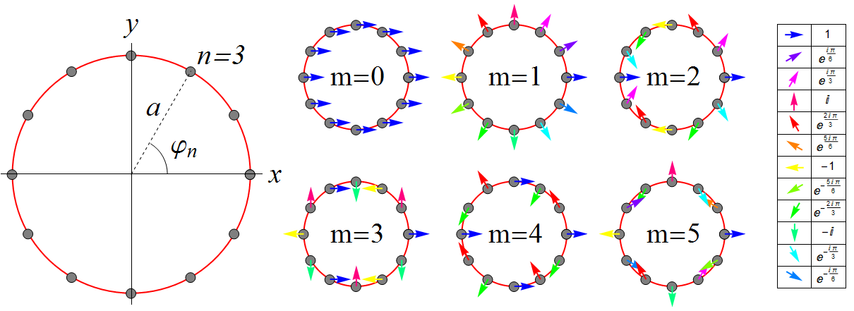
being φnsubscript𝜑𝑛\varphi_{n} the angular position of the n𝑛n-th element of the UCA, as shown in Figure 1. The set {Φmn}superscriptsubscriptΦ𝑚𝑛\left\{\varPhi_{m}^{n}\right\} can be interpreted as the discretized version of the function Φm(φ)/2πsubscriptΦ𝑚𝜑2𝜋\varPhi_{m}\left(\varphi\right)/\sqrt{2\pi}, where Φm(φ)subscriptΦ𝑚𝜑\varPhi_{m}\left(\varphi\right) is the azimuthal phase term characterizing vortex waves. Orthogonality and completeness relations (to be compared with their continuous counterparts) are also derived:

n=1N(Φjn)Φmn=n=1Nexp[iφn(mj)]N=δjm;mΦmn(Φmp)=δnp,formulae-sequencesuperscriptsubscript𝑛1𝑁superscriptsuperscriptsubscriptΦ𝑗𝑛superscriptsubscriptΦ𝑚𝑛superscriptsubscript𝑛1𝑁𝑖subscript𝜑𝑛𝑚𝑗𝑁subscript𝛿𝑗𝑚subscript𝑚superscriptsubscriptΦ𝑚𝑛superscriptsuperscriptsubscriptΦ𝑚𝑝subscript𝛿𝑛𝑝\sum_{n=1}^{N}\left(\varPhi_{j}^{n}\right)^{*}\varPhi_{m}^{n}=\sum_{n=1}^{N}\frac{\exp\left[i\varphi_{n}\left(m-j\right)\right]}{N}=\delta_{jm};\quad\sum_{m}\varPhi_{m}^{n}\left(\varPhi_{m}^{p}\right)^{*}=\delta_{np}, (2)

where the azimuthal indices m𝑚m and j𝑗j are required to span a set of N𝑁N integer values, that is [N/2,N/2)𝑁2𝑁2\left[-N/2,\>N/2\right) or (N/2,N/2]𝑁2𝑁2\left(-N/2,\>N/2\right] for N𝑁N even, in which case the extreme values ±N/2plus-or-minus𝑁2\pm N/2 lead to degenerate configurations with spurious vortex contribution111Sampling arguments can be used to show that for m=±N/2𝑚plus-or-minus𝑁2m=\pm N/2 and N𝑁N even the two corresponding phase weighting configurations {Φmn}superscriptsubscriptΦ𝑚𝑛\left\{\varPhi_{m}^{n}\right\} coincide and therefore cannot excite distinct fields. The pattern relative to such limiting cases does not represent a pure vortex wave but rather a superposition of the two., and [N/2,N/2]𝑁2𝑁2\left[-N/2,\>N/2\right] for N𝑁N odd. Both equations in (2) directly follow from the summation formula of the geometric progression to N𝑁N terms [27].

Refer to caption
Figure 1: Graphical representation of a UCA composed of N=12𝑁12N=12 elements and of the excitation coefficients ΦmnsuperscriptsubscriptΦ𝑚𝑛\varPhi_{m}^{n}, defined in (1), for some values of m𝑚m.

Let us consider a UCA of N𝑁N ideal isotropic radiators lying in the xy𝑥𝑦xy plane; the frequency-domain analytic expression of the scalar vortex wave generated by such distribution reads:

fm(𝐫)subscript𝑓𝑚𝐫\displaystyle f_{m}\left(\mathbf{r}\right) =\displaystyle= d3rg+(𝐫𝐫)n=1NΦmnδ3(𝐫𝐫n)superscript𝑑3superscript𝑟subscript𝑔𝐫superscript𝐫superscriptsubscript𝑛1𝑁superscriptsubscriptΦ𝑚𝑛superscript𝛿3superscript𝐫subscript𝐫𝑛\displaystyle\int d^{3}r^{\prime}\>g_{+}\left(\mathbf{r}\text{\textminus}\mathbf{r}^{\prime}\right)\sum_{n=1}^{N}\varPhi_{m}^{n}\delta^{3}\left(\mathbf{r}^{\prime}-\mathbf{r}_{n}\right) (3)
=\displaystyle= n=1NΦmnexp(ik|𝐫𝐫n|)4π|𝐫𝐫n|,superscriptsubscript𝑛1𝑁superscriptsubscriptΦ𝑚𝑛𝑖𝑘𝐫subscript𝐫𝑛4𝜋𝐫subscript𝐫𝑛\displaystyle-\sum_{n=1}^{N}\varPhi_{m}^{n}\frac{\exp\left(-ik\left|\mathbf{r}-\mathbf{r}_{n}\right|\right)}{4\pi\left|\mathbf{r}-\mathbf{r}_{n}\right|},

where g+subscript𝑔g_{+} is the outgoing-wave Green function defined in (26), m𝑚m is the topological charge, |m|<N/2𝑚𝑁2\left|m\right|<N/2, 𝐫nsubscript𝐫𝑛\mathbf{r}_{n} identifies the position of the n𝑛n-th spherical wave source and all dimensional constants have been neglected for simplicity. Equation (3) is derived from (27) upon proper choice of the source term. Although approximated closed-form expressions could be obtained from (3) under specific assumptions (for example, a very large number of array elements), these will not be taken into consideration for brevity. Instead, we can resort to the useful far-field approximation ramuch-greater-than𝑟𝑎r\gg a, being a𝑎a the radius of the array, which leads to:

fm(r,θ,ϕ)exp(ikr)4πNrn=1Nexp[ikasinθcos(ϕφn)+imφn],subscript𝑓𝑚𝑟𝜃italic-ϕ𝑖𝑘𝑟4𝜋𝑁𝑟superscriptsubscript𝑛1𝑁𝑖𝑘𝑎𝜃italic-ϕsubscript𝜑𝑛𝑖𝑚subscript𝜑𝑛f_{m}\left(r,\theta,\phi\right)\approx-\frac{\exp\left(-ikr\right)}{4\pi\sqrt{N}r}\sum_{n=1}^{N}\exp\left[ika\sin\theta\cos\left(\phi-\varphi_{n}\right)+im\varphi_{n}\right], (4)

where {r,θ,ϕ}𝑟𝜃italic-ϕ\left\{r,\theta,\phi\right\} represents the spherical coordinate system and the expression 𝐫n=a{cosφn,sinφn,0}subscript𝐫𝑛𝑎subscript𝜑𝑛subscript𝜑𝑛0\mathbf{r}_{n}=a\left\{\cos\varphi_{n},\sin\varphi_{n},0\right\} has been employed.

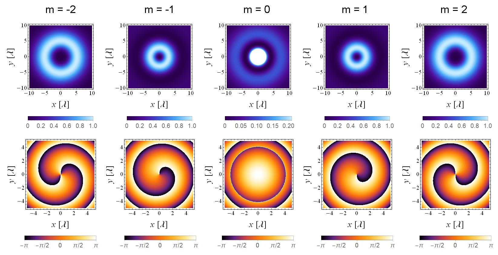
Figure 2 displays some of the transverse intensity and phase profiles of the function fm(𝐫)subscript𝑓𝑚𝐫f_{m}\left(\mathbf{r}\right) at varying m𝑚m in a fixed z𝑧z-plane for a UCA like that reported in Figure 1. The mode patterns are found to be in good agreement with those expected for a scalar vortex solution but, of course, neither (3) nor (4) suffices to describe a realistic vortex waveform.

Let us now move to the case of an arbitrary N𝑁N-element antenna array composed of more realistic radiators. The knowledge of the current term 𝐉(𝐫)𝐉𝐫\mathbf{J}\left(\mathbf{r}\right) enables the estimation of the electric and magnetic fields via (30) and (31), from which the corresponding far-field expressions are easily derived [23]. Neglecting all mutual couplings among the antennas, the total electric field radiated by the considered array in a region where r𝑟r is much greater than the spatial extent of the antennas can be written as:

𝐄(r,θ,ϕ)=ikηI0n=1Nξnexp(ik|𝐫𝐫n|)4π|𝐫𝐫n|𝐡n(θ,ϕ),𝐄𝑟𝜃italic-ϕ𝑖𝑘𝜂subscript𝐼0superscriptsubscript𝑛1𝑁subscript𝜉𝑛𝑖𝑘𝐫subscript𝐫𝑛4𝜋𝐫subscript𝐫𝑛subscript𝐡𝑛𝜃italic-ϕ\mathbf{E}\left(r,\theta,\phi\right)=ik\eta I_{0}\sum_{n=1}^{N}\xi_{n}\frac{\exp\left(-ik\left|\mathbf{r}-\mathbf{r}_{n}\right|\right)}{4\pi\left|\mathbf{r}-\mathbf{r}_{n}\right|}\,\mathbf{h}_{n}\left(\theta,\phi\right), (5)

being η𝜂\eta the vacuum impedance, In=I0ξnsubscript𝐼𝑛subscript𝐼0subscript𝜉𝑛I_{n}=I_{0}\,\xi_{n} the supply current to the n𝑛n-th radiator, where ξnsubscript𝜉𝑛\xi_{n}\in\mathbb{C} is the relative synthesis coefficient and I0subscript𝐼0I_{0} a constant current term associated to the total input power, whereas 𝐡n(θ,ϕ)subscript𝐡𝑛𝜃italic-ϕ\mathbf{h}_{n}\left(\theta,\phi\right) represents the n𝑛n-th antenna vector effective height (see A, equation (33)).

In deriving equation (5), no assumption was made on the feeding, arrangement and type of antennas employed. By specializing the array geometry to the case of a UCA in the xy𝑥𝑦xy plane, it is possible to analyze the properties of the electric field (5) associated with a set of vortex weighting coefficients ξn=Φmnsubscript𝜉𝑛superscriptsubscriptΦ𝑚𝑛\xi_{n}=\varPhi_{m}^{n}. Under this hypothesis, and for ramuch-greater-than𝑟𝑎r\gg a, the following far-field expression holds:

𝐄m(r,θ,ϕ)ikηI0exp(ikr)4πNrn=1N𝐡n(θ,ϕ)eikasinθcos(ϕφn)+imφn.subscript𝐄𝑚𝑟𝜃italic-ϕ𝑖𝑘𝜂subscript𝐼0𝑖𝑘𝑟4𝜋𝑁𝑟superscriptsubscript𝑛1𝑁subscript𝐡𝑛𝜃italic-ϕsuperscripte𝑖𝑘𝑎𝜃italic-ϕsubscript𝜑𝑛𝑖𝑚subscript𝜑𝑛\mathbf{E}_{m}\left(r,\theta,\phi\right)\approx\frac{ik\eta I_{0}\exp\left(-ikr\right)}{4\pi\sqrt{N}r}\sum_{n=1}^{N}\mathbf{h}_{n}\left(\theta,\phi\right)\mathrm{e}^{ika\sin\theta\cos\left(\phi-\varphi_{n}\right)+im\varphi_{n}}. (6)
Refer to caption
Figure 2: Relative intensity (upper row) and phase (lower row) profiles of the scalar wave fmsubscript𝑓𝑚f_{m} in (4) for a=λ=1𝑎𝜆1a=\lambda=1 m, N=12𝑁12N=12 and z=10λ𝑧10𝜆z=10\lambda. To better highlight fainter details, the m=0𝑚0m=0 intensity maximum has been clipped.
Refer to caption
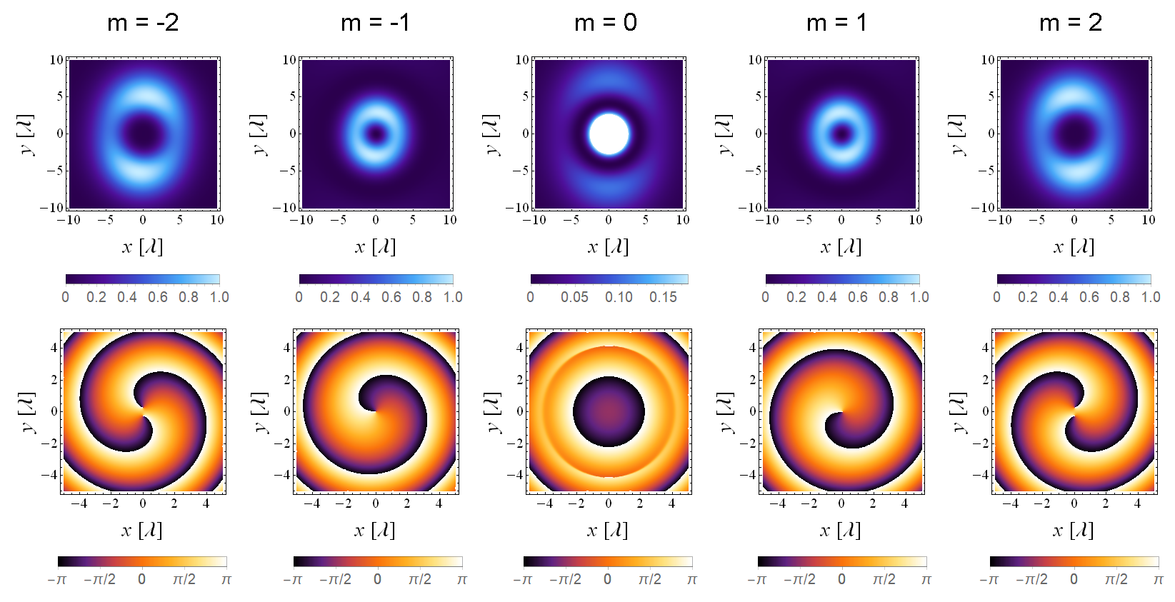
Figure 3: Relative intensity (upper row) and phase (lower row) profiles of the x𝑥x-component of the electric field (6) radiated by a UCA composed of N=12𝑁12N=12 x𝑥x-polarized half-wave dipoles, for a=λ=1𝑎𝜆1a=\lambda=1 m and z=10λ𝑧10𝜆z=10\lambda.

Some of the transverse intensity and phase profiles of the x𝑥x-component of 𝐄m(𝐫)subscript𝐄𝑚𝐫\mathbf{E}_{m}\left(\mathbf{r}\right) computed in the plane z=10λ𝑧10𝜆z=10\lambda are reported in Figure 3 for the case of a UCA composed of N=12𝑁12N=12 x𝑥x-directed half-wave dipoles. It is fundamental to note how the use of linear sources breaks the degenerate symmetry of the isotropic case, causing a deviation of the patterns from the expected ones. In particular, the intensity distributions are no longer perfectly circular and the phase profiles witness a corruption of the on-axis vortex with charge m𝑚m in m𝑚m distinct off-axis vortices with unitary charge.
Refer to caption
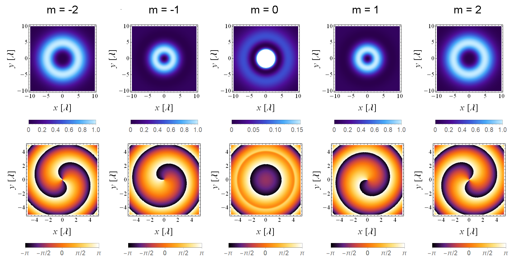
Figure 4: Relative intensity (upper row) and phase (lower row) profiles of the 𝐮xi𝐮ysubscript𝐮𝑥𝑖subscript𝐮𝑦\mathbf{u}_{x}-i\mathbf{u}_{y} component of the right circularly polarized electric field (6) radiated by a UCA composed of N=12𝑁12N=12 crossed half-wave dipoles arranged along the x𝑥x and y𝑦y directions, for a=λ=1𝑎𝜆1a=\lambda=1 m and z=10λ𝑧10𝜆z=10\lambda.

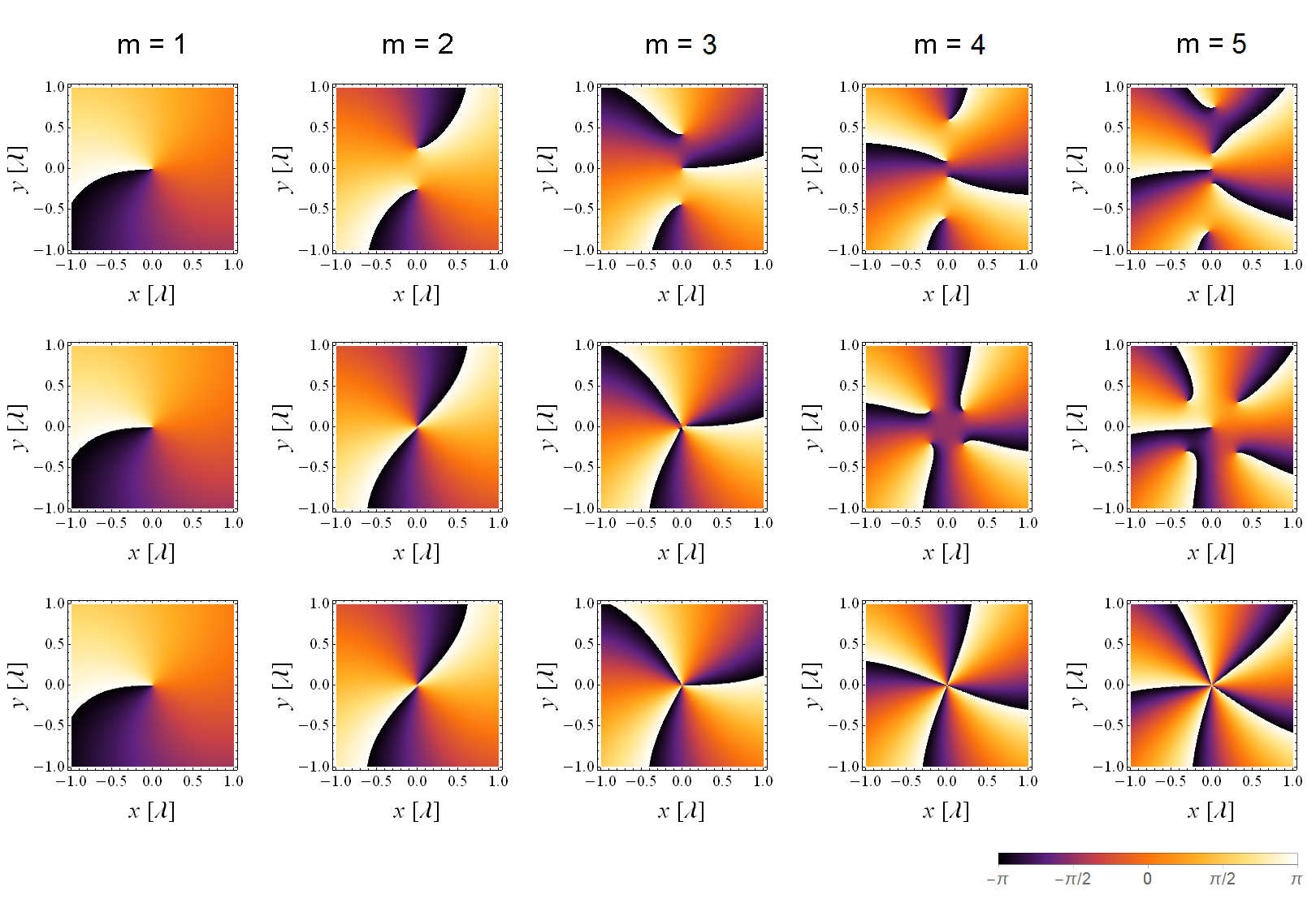
As shown in Figure 4 and in Figure 5, the standard vortex profiles can be recovered by using low-directive circular symmetric array elements such as crossed dipoles with a π/2𝜋2\pi/2 phase delay, in which case also a spin angular momentum (SAM) contribution will be present. It is worth emphasizing that circular polarization alone is not enough to completely solve the symmetry breaking of vortex waves, as confirmed by the fact that higher order profiles obtained with crossed Hertzian dipoles are better than those produced by crossed half-wave dipoles, the former type of antennas being closer to the ideal spherical wave source.

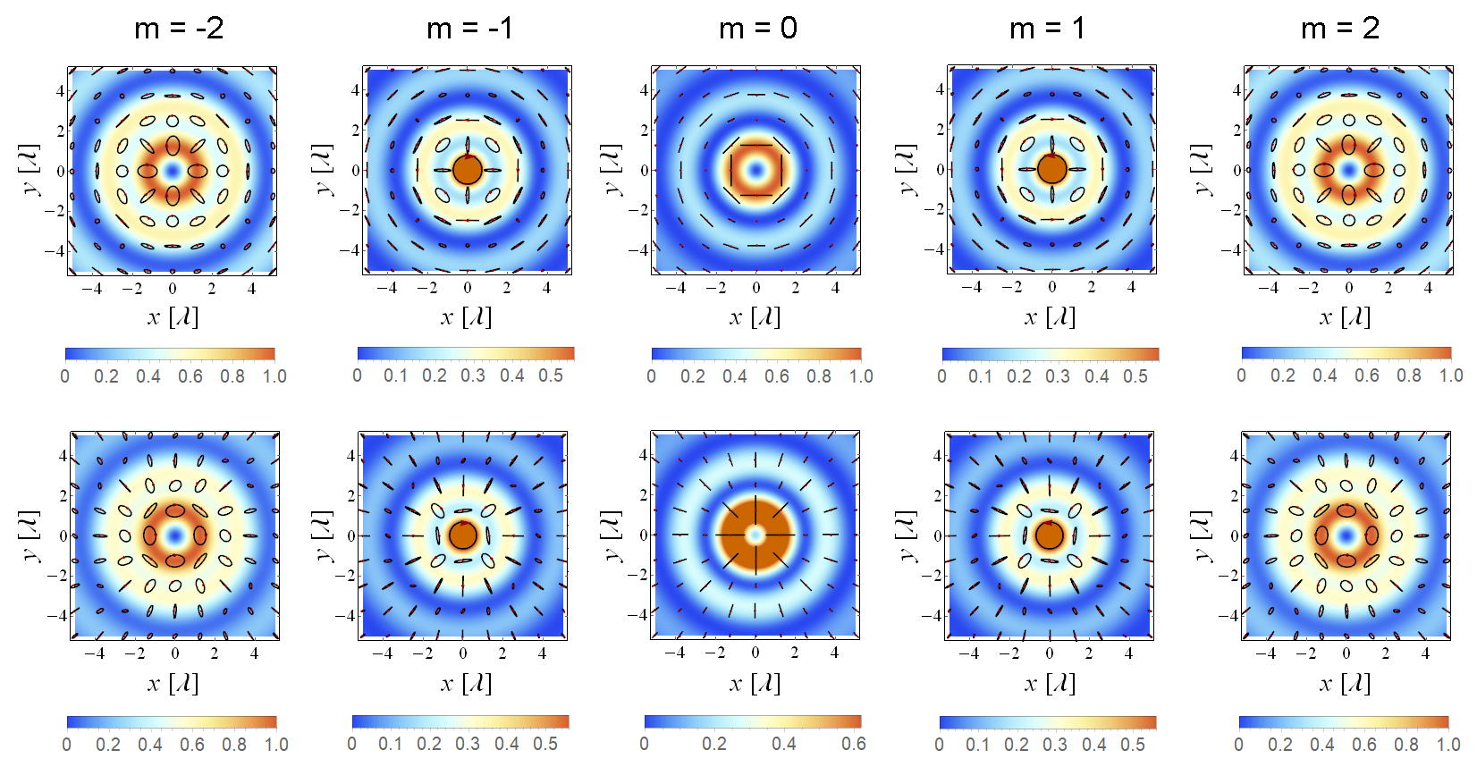
More generally, owing to the vector nature of the above equations, it is possible to reproduce approximate versions of the vector vortex solutions [28]. For instance, the azimuthally and radially polarized vector beams are found by considering UCAs of dipoles arranged in the 𝐮φsubscript𝐮𝜑\mathbf{u}_{\varphi}-direction and in the 𝐮ρsubscript𝐮𝜌\mathbf{u}_{\rho}-direction, respectively222It is interesting to note that such configurations belong to the class of the so-called ring quasi-arrays, originally proposed long ago and analyzed in connection with their supposed super-gain properties [29].. As an alternative, any physical rotation of the dipoles in the circumference plane can be replaced by a rotation of the current vectors implemented through a UCA of properly fed crossed dipoles displaced along two fixed orthogonal directions.

The electric field norm and polarization plots of some vector waves generated by UCAs of azimuthally and radially polarized half-wave dipoles are displayed in Figure 6, showing some of the interesting features that characterize the theoretical vector vortex solutions. Not surprisingly, the possibility of synthesizing vector vortex beams by means of circular arrays of sources oriented along 𝐮φsubscript𝐮𝜑\mathbf{u}_{\varphi} and 𝐮ρsubscript𝐮𝜌\mathbf{u}_{\rho} has also been explored in optics as a theoretical tool for modeling optical vortex beams emitters [30, 31].
Refer to caption
Figure 5: Phase profiles of the electric field (6) radiated by a UCA composed of N=12𝑁12N=12 half-wave dipoles (x𝑥x-component, first row), right circularly polarized crossed half-wave dipoles (𝐮xi𝐮ysubscript𝐮𝑥𝑖subscript𝐮𝑦\mathbf{u}_{x}-i\mathbf{u}_{y} component, second row) and right circularly polarized crossed Hertzian dipoles of length λ/20𝜆20\lambda/20 (𝐮xi𝐮ysubscript𝐮𝑥𝑖subscript𝐮𝑦\mathbf{u}_{x}-i\mathbf{u}_{y} component, third row), for a=λ=1𝑎𝜆1a=\lambda=1 m and z=10λ𝑧10𝜆z=10\lambda.
Refer to caption
Figure 6: Norm and polarization plots of the electric field (6) radiated by a UCA composed of N=25𝑁25N=25 half-wave dipoles arranged along the 𝐮φsubscript𝐮𝜑\mathbf{u}_{\varphi}-direction (upper row) and the 𝐮ρsubscript𝐮𝜌\mathbf{u}_{\rho}-direction (lower row), for a=1𝑎1a=1 m, λ=0.4𝜆0.4\lambda=0.4 m and z=10λ𝑧10𝜆z=10\lambda. Some of the intensity maxima have been clipped for better clarity.

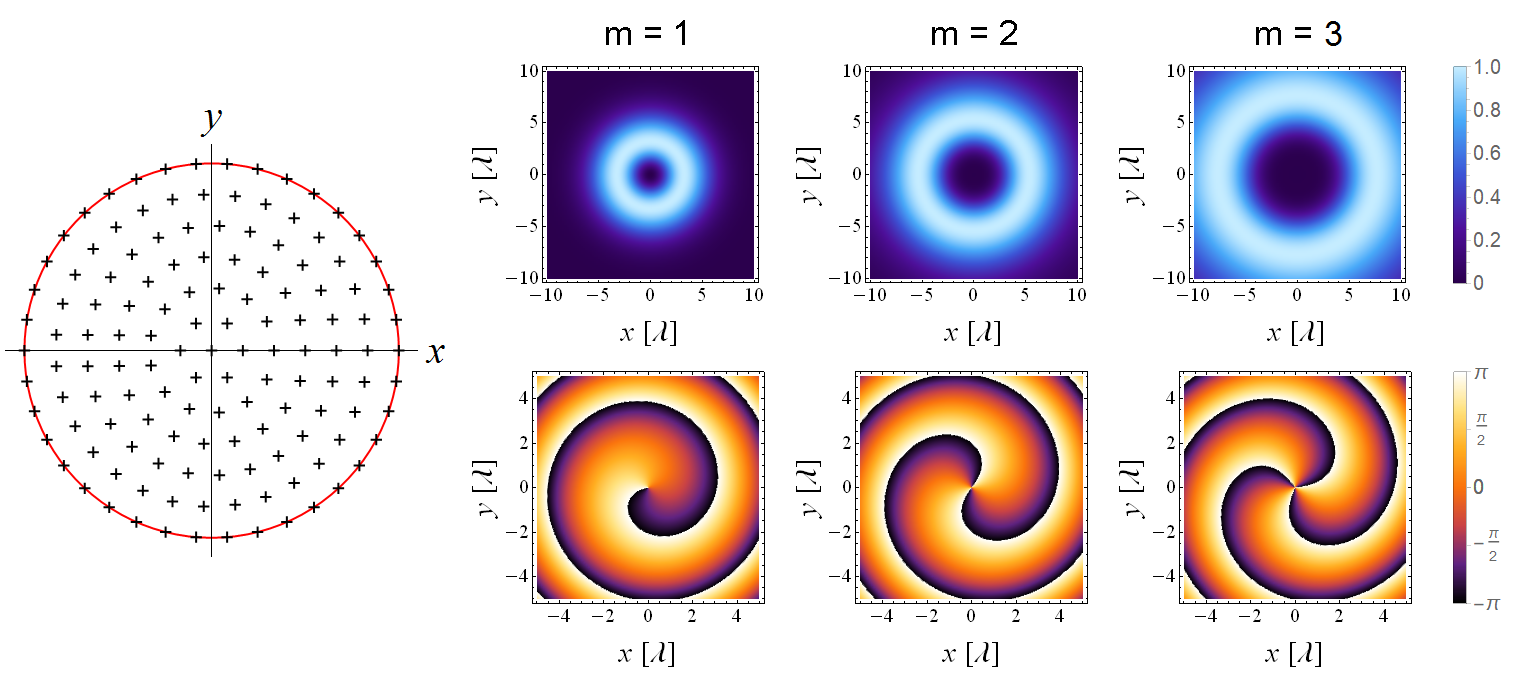
As a further point, one may wonder if it is possible to generalize the set {Φmn}superscriptsubscriptΦ𝑚𝑛\left\{\varPhi_{m}^{n}\right\} in (1) beyond the UCA case without the need for a complete array synthesis procedure (that usually requires to solve a linear inverse problem). For instance, the new set of vortex excitation coefficients could be heuristically defined via sampling of some orthogonal basis functions which contain the sought term exp(imφ)𝑖𝑚𝜑\exp\left(im\varphi\right) and are supported on the reference volume for the transmitting array. Limiting to the case of a uniform disk antenna array of radius a𝑎a, a complete set of functions that are orthogonal in the interior of the disk is provided by the well-known generalized Zernike polynomials [32]:

Zqm(ϱ,φ)=Rqm(ϱ)exp(imφ),superscriptsubscript𝑍𝑞𝑚italic-ϱ𝜑superscriptsubscript𝑅𝑞𝑚italic-ϱ𝑖𝑚𝜑Z_{q}^{m}\left(\varrho,\varphi\right)=R_{q}^{m}\left(\varrho\right)\exp\left(im\varphi\right), (7)

where ϱ=ρ/aitalic-ϱ𝜌𝑎\varrho=\rho/a represents the scaled radial coordinate, m𝑚m is the azimuthal index, q|m|𝑞𝑚q\leq\left|m\right| corresponds to a non-negative integer such that q|m|𝑞𝑚q-\left|m\right| is even and the radial function is expressed by:

Rqm(ϱ)=s=0q|m|2(1)s(qs)!s!(q+|m|2s)!(q|m|2s)!ϱq2s.superscriptsubscript𝑅𝑞𝑚italic-ϱsuperscriptsubscript𝑠0𝑞𝑚2superscript1𝑠𝑞𝑠𝑠𝑞𝑚2𝑠𝑞𝑚2𝑠superscriptitalic-ϱ𝑞2𝑠R_{q}^{m}\left(\varrho\right)=\sum_{s=0}^{\frac{q-\left|m\right|}{2}}\frac{\left(-1\right)^{s}\left(q-s\right)!}{s!\left(\frac{q+\left|m\right|}{2}-s\right)!\left(\frac{q-\left|m\right|}{2}-s\right)!}\varrho^{q-2s}. (8)

For each of the N𝑁N antennas regularly distributed over the transmitting disk, Zqm(ϱn,φn)superscriptsubscript𝑍𝑞𝑚subscriptitalic-ϱ𝑛subscript𝜑𝑛Z_{q}^{m}\left(\varrho_{n},\varphi_{n}\right) identifies the local value of the Zernike function with indices q𝑞q and m𝑚m and can be used to build a corresponding column vector of vortex excitations for the array. It should be remembered that the discretization introduces bounds on the possible values of the azimuthal and radial indices and limits the number of effectively orthogonal column vectors.

Refer to caption
Figure 7: Synthesis of some vortex waves via sampling of the Zernike polynomials on a uniform disk array of x𝑥x-polarized Hertzian dipoles of length λ/20𝜆20\lambda/20: sketch of the geometry (left), relative intensity and phase profiles of the x𝑥x-component of the synthesized electric field evaluated at z=10λ𝑧10𝜆z=10\lambda (right), for N=133𝑁133N=133 and a=λ=1𝑎𝜆1a=\lambda=1 m.
Refer to caption
Figure 8: Synthesis of some vortex waves via sampling of the Zernike polynomials on a uniform disk array of right circularly polarized crossed Hertzian dipoles of length λ/20𝜆20\lambda/20: sketch of the geometry (left), relative intensity and phase profiles of the 𝐮xi𝐮ysubscript𝐮𝑥𝑖subscript𝐮𝑦\mathbf{u}_{x}-i\mathbf{u}_{y} component of the synthesized electric field evaluated at z=10λ𝑧10𝜆z=10\lambda (right), for N=133𝑁133N=133 and a=λ=1𝑎𝜆1a=\lambda=1 m.

For the sake of simplicity, let us neglect the radial degrees of freedom by fixing q=|m|𝑞𝑚q=\left|m\right| and consider the set made of the N𝑁N-length column vectors {Z|m|m(ϱn,φn)}superscriptsubscript𝑍𝑚𝑚subscriptitalic-ϱ𝑛subscript𝜑𝑛\left\{Z_{\left|m\right|}^{m}\left(\varrho_{n},\varphi_{n}\right)\right\}.

Figure 7 and Figure 8 display the electric field profiles relative to some of the effectively orthogonal sampled coefficients for a disk array composed of uniformly spaced x𝑥x-directed Hertzian dipoles and circularly polarized crossed Hertzian dipoles, respectively. The results are easily interpreted in accordance with what seen above and could be generalized to other geometries.

3 Basis sets and circular symmetry

As suggested by David A. B. Miller in [33], the orthogonal spatial information channels, also referred to as the communications modes or simply the channel modes, can be interpreted as the pairs of functions that diagonalize the mathematical operator formalizing the communications between the transmitting and the receiving volumes. In B, the abstract operator is specialized to the case of a finite-dimensional channel matrix which describes the communications between two arbitrary antenna arrays. The same concepts are applied to some specific examples in the present section. Within the proposed framework, the singular vectors of the channel matrix are analyzed in relation to the standard vortex modes basis, shedding light onto some of the interesting features that arise from the intimate connection between system geometry and symmetry properties of the channel modes.

In the following, transmitting and receiving arrays are considered identical in spatial disposition, number of elements, labeling order and type of constituent antennas, for simplicity. Under this assumption, the Cartesian coordinates 𝐫pR={xpR,ypR,zpR}superscriptsubscript𝐫𝑝𝑅superscriptsubscript𝑥𝑝𝑅superscriptsubscript𝑦𝑝𝑅superscriptsubscript𝑧𝑝𝑅\mathbf{r}_{p}^{R}=\left\{x_{p}^{R},y_{p}^{R},z_{p}^{R}\right\} defining the locations of the receiving elements are linked to those relative to the transmitting ones 𝐫nT={xnT,ynT,znT}superscriptsubscript𝐫𝑛𝑇superscriptsubscript𝑥𝑛𝑇superscriptsubscript𝑦𝑛𝑇superscriptsubscript𝑧𝑛𝑇\mathbf{r}_{n}^{T}=\left\{x_{n}^{T},y_{n}^{T},z_{n}^{T}\right\} via the matrix equation:

𝐫pR=𝖱𝐫pT+𝐭,superscriptsubscript𝐫𝑝𝑅𝖱superscriptsubscript𝐫𝑝𝑇𝐭\mathbf{r}_{p}^{R}=\mathsf{R}\,\mathbf{r}_{p}^{T}+\mathsf{\mathbf{t}}, (9)

where 𝖱𝖱\mathsf{R} represents a three-dimensional rotation matrix and 𝐭𝐭\mathsf{\mathbf{t}} a translation vector (for instance, 𝖱=𝕀𝖱𝕀\mathsf{R}=\mathbb{I} and 𝐭={0,0,d}𝐭00𝑑\mathsf{\mathbf{t}}=\left\{0,0,d\right\} in the case of perfectly aligned antenna arrays separated by a distance d𝑑d). From simple geometrical arguments, the set of unit vectors 𝐯={𝐮x,𝐮y,𝐮z}𝐯subscript𝐮𝑥subscript𝐮𝑦subscript𝐮𝑧\mathbf{v}=\left\{\mathbf{u}_{x},\mathbf{u}_{y},\mathbf{u}_{z}\right\} employed to describe the antenna orientation transforms accordingly:

𝐯pR=𝖱1𝐯pT.superscriptsubscript𝐯𝑝𝑅superscript𝖱1superscriptsubscript𝐯𝑝𝑇\mathbf{v}_{p}^{R}=\mathsf{R}^{-1}\mathbf{v}_{p}^{T}. (10)

As a straightforward example, let 𝒱Tsubscript𝒱𝑇\mathcal{V}_{T} and 𝒱Rsubscript𝒱𝑅\mathcal{V}_{R} be two identical facing circumferences of radius a𝑎a at a distance d𝑑d apart and suppose two UCAs composed of N𝑁N x𝑥x-polarized Hertzian dipoles of length l𝑙l to be arranged along such circumferences. Since the effective height of a z𝑧z-directed Hertzian antenna placed in the origin reads lsinθ𝐮θ𝑙𝜃subscript𝐮𝜃l\sin\theta\,\mathbf{u}_{\theta}, the channel matrix (40) for this aligned communication system is simply given by:

Hpn=ikηI0exp(ik|𝐫pR𝐫nT|)4π|𝐫pR𝐫nT|(lsinθnpx)2,subscript𝐻𝑝𝑛𝑖𝑘𝜂subscript𝐼0𝑖𝑘superscriptsubscript𝐫𝑝𝑅superscriptsubscript𝐫𝑛𝑇4𝜋superscriptsubscript𝐫𝑝𝑅superscriptsubscript𝐫𝑛𝑇superscript𝑙superscriptsubscript𝜃𝑛𝑝𝑥2H_{pn}=ik\eta I_{0}\frac{\exp\left(-ik\left|\mathbf{r}_{p}^{R}-\mathbf{r}_{n}^{T}\right|\right)}{4\pi\left|\mathbf{r}_{p}^{R}-\mathbf{r}_{n}^{T}\right|}\left(l\sin\theta_{np}^{x}\right)^{2}, (11)

being θnpxsuperscriptsubscript𝜃𝑛𝑝𝑥\theta_{np}^{x} the angle between the vector (𝐫pR𝐫nT)superscriptsubscript𝐫𝑝𝑅superscriptsubscript𝐫𝑛𝑇\left(\mathbf{r}_{p}^{R}-\mathbf{r}_{n}^{T}\right) and the x𝑥x-axis. On using the explicit expressions for 𝐫pRsuperscriptsubscript𝐫𝑝𝑅\mathbf{r}_{p}^{R} and 𝐫nTsuperscriptsubscript𝐫𝑛𝑇\mathbf{r}_{n}^{T}, equation (11) reduces to:

Hpn=ikηI0exp(ikd2+2a2{1cos[2π(pn)N]})4πd2+2a2{1cos[2π(pn)N]}(lsinθnpx)2.subscript𝐻𝑝𝑛𝑖𝑘𝜂subscript𝐼0𝑖𝑘superscript𝑑22superscript𝑎212𝜋𝑝𝑛𝑁4𝜋superscript𝑑22superscript𝑎212𝜋𝑝𝑛𝑁superscript𝑙superscriptsubscript𝜃𝑛𝑝𝑥2H_{pn}=ik\eta I_{0}\frac{\exp\left(-ik\sqrt{d^{2}+2a^{2}\left\{1-\cos\left[\frac{2\pi\left(p-n\right)}{N}\right]\right\}}\right)}{4\pi\sqrt{d^{2}+2a^{2}\left\{1-\cos\left[\frac{2\pi\left(p-n\right)}{N}\right]\right\}}}\left(l\sin\theta_{np}^{x}\right)^{2}. (12)

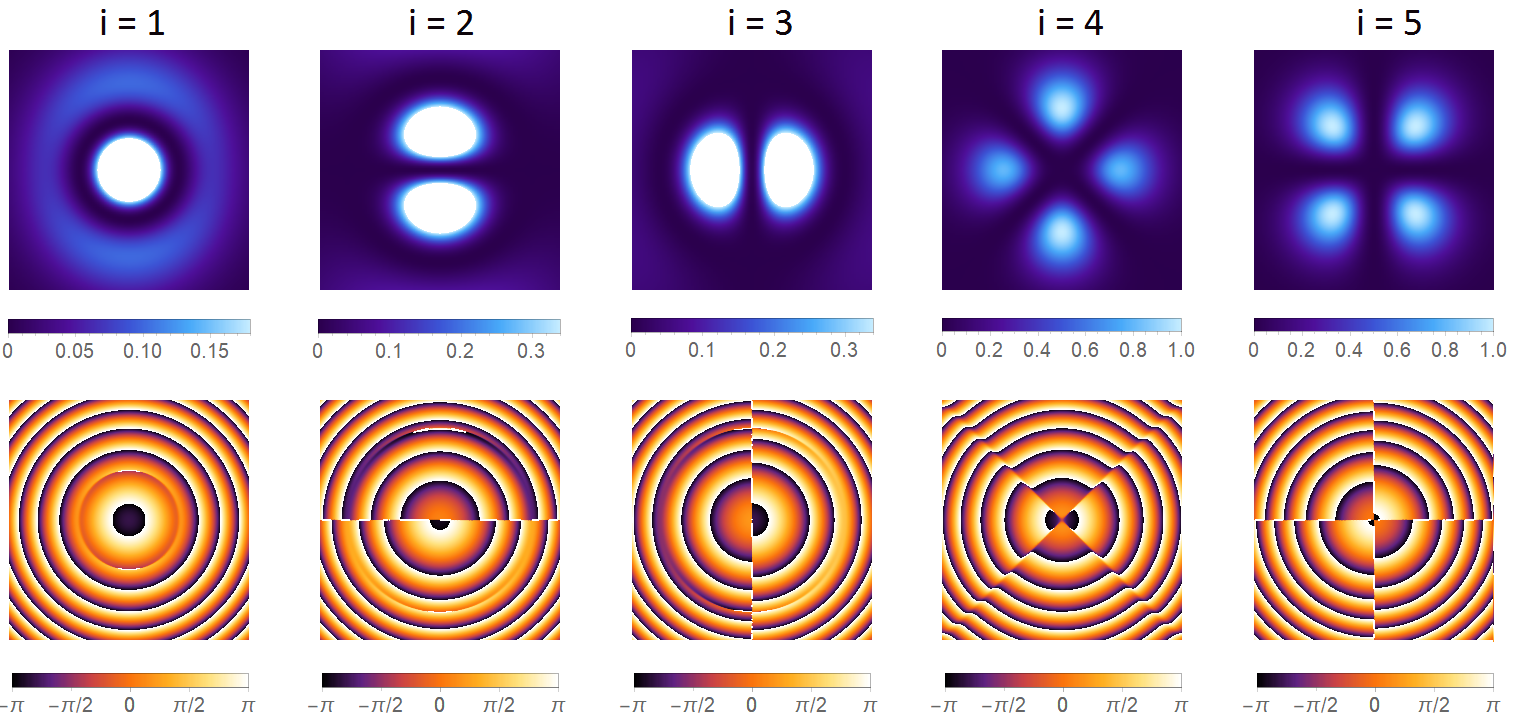
In Figure 9 are reported some density plots of the electric field radiated in the transverse plane z=d=10λ𝑧𝑑10𝜆z=d=10\lambda by the transmitting UCA when the first five right singular vectors of the channel matrix (12) are employed as excitation coefficients.
Refer to caption
Figure 9: Norm (upper row) and phase (x𝑥x-component, lower row) profiles of the electric field radiated by a UCA composed of N=25𝑁25N=25 x𝑥x-polarized Hertzian dipoles with excitation coefficients given by the right singular vectors {ξn(i)}superscriptsubscript𝜉𝑛𝑖\left\{\xi_{n}^{(i)}\right\} of the channel matrix (12), for a=λ=1𝑎𝜆1a=\lambda=1 m, l=λ/20𝑙𝜆20l=\lambda/20, d=10λ𝑑10𝜆d=10\lambda. A clipping of the first three intensity maxima has been introduced to avoid faint plots.

Analogous profiles can be found for the left singular vectors. Despite no one of the wavefields excited by the considered channel modes presents vortex character, some important subtleties are involved and will now be discussed.

In order to minimize the notation, let |m={Φmn}ket𝑚superscriptsubscriptΦ𝑚𝑛\left|m\right\rangle=\left\{\varPhi_{m}^{n}\right\} be a column vector in Nsuperscript𝑁\mathbb{C}^{N} and suppose the azimuthal index value m𝑚m to be specified via the following rule:

mj={N2+j1Neven;N12+j1Nodd,subscript𝑚𝑗cases𝑁2𝑗1𝑁even𝑁12𝑗1𝑁oddm_{j}=\begin{cases}-\frac{N}{2}+j-1&N\>\mathrm{even};\\ -\frac{N-1}{2}+j-1&N\>\mathrm{odd},\end{cases} (13)

with j𝑗j running from 111 to N𝑁N. By this convention, the collection {|mj}ketsubscript𝑚𝑗\left\{\left|m_{j}\right\rangle\right\} provides a basis set for the space of all the possible UCA excitations |ξ={ξn}ket𝜉subscript𝜉𝑛\left|\xi\right\rangle=\left\{\xi_{n}\right\} and the orthogonality and completeness relations (2) can be rewritten in Dirac notation:

mi|mj=δij;j=1N|mjmj|=𝕀,formulae-sequenceinner-productsubscript𝑚𝑖subscript𝑚𝑗subscript𝛿𝑖𝑗superscriptsubscript𝑗1𝑁ketsubscript𝑚𝑗brasubscript𝑚𝑗𝕀\left\langle m_{i}\right.\left|m_{j}\right\rangle=\delta_{ij};\quad\sum_{j=1}^{N}\left|m_{j}\right\rangle\left\langle m_{j}\right|=\mathbb{I}, (14)

where 𝕀𝕀\mathbb{I} is the N×N𝑁𝑁N\times N identity matrix. Now, labeling the i𝑖i-th right singular vector of the channel matrix with |ei={ξn(i)}ketsubscript𝑒𝑖superscriptsubscript𝜉𝑛𝑖\left|e_{i}\right\rangle=\left\{\xi_{n}^{(i)}\right\}, the scalar product:

cji=mj|eisubscript𝑐𝑗𝑖inner-productsubscript𝑚𝑗subscript𝑒𝑖c_{ji}=\left\langle m_{j}\right.\left|e_{i}\right\rangle (15)

can be understood as the j𝑗j-th expansion coefficient of |eiketsubscript𝑒𝑖\left|e_{i}\right\rangle over the vortex modes basis {|mj}ketsubscript𝑚𝑗\left\{\left|m_{j}\right\rangle\right\}, namely:

|ei=j=1N|mjmj|ei=j=1Ncji|mj,ketsubscript𝑒𝑖superscriptsubscript𝑗1𝑁ketsubscript𝑚𝑗inner-productsubscript𝑚𝑗subscript𝑒𝑖superscriptsubscript𝑗1𝑁subscript𝑐𝑗𝑖ketsubscript𝑚𝑗\left|e_{i}\right\rangle=\sum_{j=1}^{N}\left|m_{j}\right\rangle\left\langle m_{j}\right.\left|e_{i}\right\rangle=\sum_{j=1}^{N}c_{ji}\left|m_{j}\right\rangle, (16)

as follows from the completeness condition.

Figure 10 (left) displays the projection (15) for the right singular vectors of the channel matrix (12), highlighting the presence of spurious vortex contributions in the matrix spectrum.

Refer to caption
Figure 10: Spectral analysis of the channel operator (12): matrix plot of the scalar product cjisubscript𝑐𝑗𝑖c_{ji} defined in (15) (left) and singular values of Hpnsubscript𝐻𝑝𝑛H_{pn} as a function of the spectral index (right), for N=25𝑁25N=25, a=λ=1𝑎𝜆1a=\lambda=1 m, l=λ/20𝑙𝜆20l=\lambda/20, d=10λ𝑑10𝜆d=10\lambda.

This circumstance can be traced back to the use of non-isotropic antennas, as clarified by considering a simplified version of (12):

Hpn()=ikηI0l2exp(ikd2+2a2{1cos[2π(pn)N]})4πd2+2a2{1cos[2π(pn)N]},superscriptsubscript𝐻𝑝𝑛𝑖𝑘𝜂subscript𝐼0superscript𝑙2𝑖𝑘superscript𝑑22superscript𝑎212𝜋𝑝𝑛𝑁4𝜋superscript𝑑22superscript𝑎212𝜋𝑝𝑛𝑁H_{pn}^{(\circ)}=ik\eta I_{0}l^{2}\frac{\exp\left(-ik\sqrt{d^{2}+2a^{2}\left\{1-\cos\left[\frac{2\pi\left(p-n\right)}{N}\right]\right\}}\right)}{4\pi\sqrt{d^{2}+2a^{2}\left\{1-\cos\left[\frac{2\pi\left(p-n\right)}{N}\right]\right\}}}, (17)

where the directivity of the arrays elements has been neglected and the label (∘) means “isotropic case”. The projection of the right singular vectors relative to (17) on the vortex modes basis is reported in Figure 11 (left), from which it is apparent that each singular vector represents an exact superposition of two vortex modes with opposite topological charges, i.e. ±mplus-or-minus𝑚\pm m.

As it is clear from both Figure 10 and Figure 11, the singular values of the channel matrix for the transmission between facing UCAs are two-fold degenerate due to the fact that, when resolved in terms of the vortex modes, there is no difference between two configurations with opposite m𝑚m (more on this in D). In the isotropic case (17), pure vortex modes can be directly obtained by implementing a rotation of the singular vectors in their corresponding eigenspaces so as to select one of the two directions along which there is no coexistence of opposite azimuthal indices; in this sense, vortex modes constitute a legitimate basis of singular vectors. This is not surprising, since it has been shown that Hpn()superscriptsubscript𝐻𝑝𝑛H_{pn}^{(\circ)} is diagonalized by the discrete Fourier transform (DFT) matrix Tpi=Φmipsubscript𝑇𝑝𝑖superscriptsubscriptΦsubscript𝑚𝑖𝑝T_{pi}=\varPhi_{m_{i}}^{p}, as it only depends on the difference (pn)𝑝𝑛\left(p-n\right), and is therefore circulant [34].

Refer to caption
Figure 11: Spectral analysis of the channel operator (17): matrix plot of the scalar product cjisubscript𝑐𝑗𝑖c_{ji} (left) and singular values of Hpn()superscriptsubscript𝐻𝑝𝑛H_{pn}^{(\circ)} as a function of the spectral index (right), for N=25𝑁25N=25, a=λ=1𝑎𝜆1a=\lambda=1 m, l=λ/20𝑙𝜆20l=\lambda/20, d=10λ𝑑10𝜆d=10\lambda.

While ensuring a pure vortex spectrum of the channel matrix, the removal of the antennas directivity is nonphysical and does not prevent that the radiated vortex waves still reveal some of the inaccuracies shown in Figure 3, unless also the polarization constraint is removed (in which case the electric field must be replaced by a less realistic scalar function).

The above considerations naturally lead to question whether it is possible to get results close to that obtained for the isotropic case without compromising antennas directivity and vector character of the fields. When complex array layouts are involved, synthesis techniques must be employed to determine a proper set of beamforming coefficients able to yield approximations of the sought vortex fields; in this context, the synthesized set might not represent a basis of singular vectors (especially whenever the circular symmetry is not fully guaranteed) or, if it were, there could be no reason to prefer the vortex set over any other. On the contrary, the possibility of relying on the well-known a priori set of coefficients {Φmn}superscriptsubscriptΦ𝑚𝑛\left\{\varPhi_{m}^{n}\right\} as the very basis which diagonalizes the channel matrix in a scenario involving UCAs would be of great benefit for some applications, where it may bring technological simplifications.

To generate pure vortex beams when only simple UCAs are concerned, we replace the x𝑥x-directed elements in the system above with circularly polarized crossed dipoles that provide a major degree of rotational symmetry. Assuming the dipoles of each pair to be oriented along the x𝑥x-axis and the y𝑦y-axis, respectively, the channel matrix can be written as the scalar product:

Hpn(×)=(𝐄nx+sT𝐄ny2)(𝐡px+sR𝐡py2),superscriptsubscript𝐻𝑝𝑛superscriptsubscript𝐄𝑛𝑥subscript𝑠𝑇superscriptsubscript𝐄𝑛𝑦2superscriptsubscript𝐡𝑝𝑥subscript𝑠𝑅superscriptsubscript𝐡𝑝𝑦2H_{pn}^{(\times)}=\left(\frac{\mathbf{E}_{n}^{x}+s_{T}\mathbf{E}_{n}^{y}}{\sqrt{2}}\right)\cdot\left(\frac{\mathbf{h}_{p}^{x}+s_{R}\mathbf{h}_{p}^{y}}{\sqrt{2}}\right), (18)

with 𝐄nxsuperscriptsubscript𝐄𝑛𝑥\mathbf{E}_{n}^{x} and 𝐄nysuperscriptsubscript𝐄𝑛𝑦\mathbf{E}_{n}^{y} representing the electric fields radiated by the x𝑥x-directed and by the y𝑦y-directed elements of the n𝑛n-th pair, respectively, and 𝐡pxsuperscriptsubscript𝐡𝑝𝑥\mathbf{h}_{p}^{x}, 𝐡pysuperscriptsubscript𝐡𝑝𝑦\mathbf{h}_{p}^{y} the effective heights of the p𝑝p-th receiving pair. In (18), where the label (×) stands for “crossed dipoles case”, the complex term sTsubscript𝑠𝑇s_{T} corresponds to the ratio between the supply currents of the y𝑦y-polarized and x𝑥x-polarized elements, which is supposed to be the same for all the N𝑁N pairs; similarly, a further term sRsubscript𝑠𝑅s_{R} has been introduced in the receiving pairs which accounts for a possible beamforming phase shift between the signals collected along the two orthogonal directions. A fifty-fifty power splitting between the two elements of each pair is enforced at both the transmitting and the receiving sides through the factors 1/2121/\sqrt{2}. When sT=±isubscript𝑠𝑇plus-or-minus𝑖s_{T}=\pm i, a circularly polarized electric field is generated along the propagation axis and the choice sR=sTsubscript𝑠𝑅superscriptsubscript𝑠𝑇s_{R}=s_{T}^{*} correctly implements the required chirality inversion upon reception.

For the considered case of facing UCAs, equation (18) reduces to:

Hpn(×)superscriptsubscript𝐻𝑝𝑛\displaystyle H_{pn}^{(\times)} =\displaystyle= [(sinθnpx)2+sTsR(sinθnpy)2+sinθnpxsinθnpy(sT+sR)𝜽npx𝜽npy]delimited-[]superscriptsuperscriptsubscript𝜃𝑛𝑝𝑥2subscript𝑠𝑇subscript𝑠𝑅superscriptsuperscriptsubscript𝜃𝑛𝑝𝑦2superscriptsubscript𝜃𝑛𝑝𝑥superscriptsubscript𝜃𝑛𝑝𝑦subscript𝑠𝑇subscript𝑠𝑅superscriptsubscript𝜽𝑛𝑝𝑥superscriptsubscript𝜽𝑛𝑝𝑦\displaystyle\left[\left(\sin\theta_{np}^{x}\right)^{2}+s_{T}s_{R}\left(\sin\theta_{np}^{y}\right)^{2}+\sin\theta_{np}^{x}\sin\theta_{np}^{y}\left(s_{T}+s_{R}\right)\boldsymbol{\theta}_{np}^{x}\cdot\boldsymbol{\theta}_{np}^{y}\right] (19)
×\displaystyle\times ikηI02l2exp(ikd2+2a2{1cos[2π(pn)N]})4πd2+2a2{1cos[2π(pn)N]},𝑖𝑘𝜂subscript𝐼02superscript𝑙2𝑖𝑘superscript𝑑22superscript𝑎212𝜋𝑝𝑛𝑁4𝜋superscript𝑑22superscript𝑎212𝜋𝑝𝑛𝑁\displaystyle ik\eta\frac{I_{0}}{2}l^{2}\frac{\exp\left(-ik\sqrt{d^{2}+2a^{2}\left\{1-\cos\left[\frac{2\pi\left(p-n\right)}{N}\right]\right\}}\right)}{4\pi\sqrt{d^{2}+2a^{2}\left\{1-\cos\left[\frac{2\pi\left(p-n\right)}{N}\right]\right\}}},

where the following conventions have been introduced:

𝐫npsubscript𝐫𝑛𝑝\displaystyle\mathbf{r}_{np} =\displaystyle= {xnp,ynp,znp}=𝐫pR𝐫nT;subscript𝑥𝑛𝑝subscript𝑦𝑛𝑝subscript𝑧𝑛𝑝superscriptsubscript𝐫𝑝𝑅superscriptsubscript𝐫𝑛𝑇\displaystyle\left\{x_{np},y_{np},z_{np}\right\}=\mathbf{r}_{p}^{R}-\mathbf{r}_{n}^{T}; (20)
θnpxsuperscriptsubscript𝜃𝑛𝑝𝑥\displaystyle\theta_{np}^{x} =\displaystyle= arccos(xnp/rnp);ϕnpx=arctan(znp/ynp);subscript𝑥𝑛𝑝subscript𝑟𝑛𝑝superscriptsubscriptitalic-ϕ𝑛𝑝𝑥subscript𝑧𝑛𝑝subscript𝑦𝑛𝑝\displaystyle\arccos\left(x_{np}/r_{np}\right);\quad\phi_{np}^{x}=\arctan\left(z_{np}/y_{np}\right); (21)
𝜽npxsuperscriptsubscript𝜽𝑛𝑝𝑥\displaystyle\boldsymbol{\theta}_{np}^{x} =\displaystyle= {sinθnpx,cosθnpxcosϕnpx,cosθnpxsinϕnpx};superscriptsubscript𝜃𝑛𝑝𝑥superscriptsubscript𝜃𝑛𝑝𝑥superscriptsubscriptitalic-ϕ𝑛𝑝𝑥superscriptsubscript𝜃𝑛𝑝𝑥superscriptsubscriptitalic-ϕ𝑛𝑝𝑥\displaystyle\left\{-\sin\theta_{np}^{x},\cos\theta_{np}^{x}\cos\phi_{np}^{x},\cos\theta_{np}^{x}\sin\phi_{np}^{x}\right\}; (22)
θnpysuperscriptsubscript𝜃𝑛𝑝𝑦\displaystyle\theta_{np}^{y} =\displaystyle= arccos(ynp/rnp);ϕnpy=arctan(xnp/znp);subscript𝑦𝑛𝑝subscript𝑟𝑛𝑝superscriptsubscriptitalic-ϕ𝑛𝑝𝑦subscript𝑥𝑛𝑝subscript𝑧𝑛𝑝\displaystyle\arccos\left(y_{np}/r_{np}\right);\quad\phi_{np}^{y}=\arctan\left(x_{np}/z_{np}\right); (23)
𝜽npysuperscriptsubscript𝜽𝑛𝑝𝑦\displaystyle\boldsymbol{\theta}_{np}^{y} =\displaystyle= {cosθnpysinϕnpy,sinθnpy,cosθnpycosϕnpy}.superscriptsubscript𝜃𝑛𝑝𝑦superscriptsubscriptitalic-ϕ𝑛𝑝𝑦superscriptsubscript𝜃𝑛𝑝𝑦superscriptsubscript𝜃𝑛𝑝𝑦superscriptsubscriptitalic-ϕ𝑛𝑝𝑦\displaystyle\left\{\cos\theta_{np}^{y}\sin\phi_{np}^{y},-\sin\theta_{np}^{y},\cos\theta_{np}^{y}\cos\phi_{np}^{y}\right\}. (24)

Expressions (21) to (24) identify the spherical coordinates and polar unit vectors relative to 𝐫npsubscript𝐫𝑛𝑝\mathbf{r}_{np} in the reference frames fixed to the x𝑥x-directed and y𝑦y-directed element of the n𝑛n-th transmitting pair and oriented accordingly; under relabeling np𝑛𝑝n\leftrightarrow p, the same expressions are used to represent the vector 𝐫pn=𝐫npsubscript𝐫𝑝𝑛subscript𝐫𝑛𝑝\mathbf{r}_{pn}=-\mathbf{r}_{np} in the reference frames relative to the p𝑝p-th receiving pair. It is important to emphasize that equation (19) is correct only under the assumption that the two UCAs are perfectly aligned, in which case θpnx;y=πθnpx;ysuperscriptsubscript𝜃𝑝𝑛𝑥𝑦𝜋superscriptsubscript𝜃𝑛𝑝𝑥𝑦\theta_{pn}^{x;y}=\pi-\theta_{np}^{x;y}, ϕpnx;y=π+ϕnpx;ysuperscriptsubscriptitalic-ϕ𝑝𝑛𝑥𝑦𝜋superscriptsubscriptitalic-ϕ𝑛𝑝𝑥𝑦\phi_{pn}^{x;y}=\pi+\phi_{np}^{x;y}, 𝜽pnx;y=𝜽npx;ysuperscriptsubscript𝜽𝑝𝑛𝑥𝑦superscriptsubscript𝜽𝑛𝑝𝑥𝑦\boldsymbol{\theta}_{pn}^{x;y}=\boldsymbol{\theta}_{np}^{x;y}, 𝜽npx;y𝜽npx;y=1superscriptsubscript𝜽𝑛𝑝𝑥𝑦superscriptsubscript𝜽𝑛𝑝𝑥𝑦1\boldsymbol{\theta}_{np}^{x;y}\cdot\boldsymbol{\theta}_{np}^{x;y}=1.

With the choice sT=±isubscript𝑠𝑇plus-or-minus𝑖s_{T}=\pm i, sR=isubscript𝑠𝑅minus-or-plus𝑖s_{R}=\mp i, (19) becomes:

Hpn(±)superscriptsubscript𝐻𝑝𝑛plus-or-minus\displaystyle H_{pn}^{(\pm)} =\displaystyle= [1+d2d2+2a2{1cos[2π(pn)N]}]delimited-[]1superscript𝑑2superscript𝑑22superscript𝑎212𝜋𝑝𝑛𝑁\displaystyle\left[1+\frac{d^{2}}{d^{2}+2a^{2}\left\{1-\cos\left[\frac{2\pi\left(p-n\right)}{N}\right]\right\}}\right] (25)
×\displaystyle\times ikηI02l2exp(ikd2+2a2{1cos[2π(pn)N]})4πd2+2a2{1cos[2π(pn)N]},𝑖𝑘𝜂subscript𝐼02superscript𝑙2𝑖𝑘superscript𝑑22superscript𝑎212𝜋𝑝𝑛𝑁4𝜋superscript𝑑22superscript𝑎212𝜋𝑝𝑛𝑁\displaystyle ik\eta\frac{I_{0}}{2}l^{2}\frac{\exp\left(-ik\sqrt{d^{2}+2a^{2}\left\{1-\cos\left[\frac{2\pi\left(p-n\right)}{N}\right]\right\}}\right)}{4\pi\sqrt{d^{2}+2a^{2}\left\{1-\cos\left[\frac{2\pi\left(p-n\right)}{N}\right]\right\}}},

which is again a circulant matrix, as also evidenced by the strong similarity between Figure 11 and Figure 12.

Refer to caption
Figure 12: Spectral analysis of the channel operator (19): matrix plot of the scalar product cjisubscript𝑐𝑗𝑖c_{ji} (left) and singular values of Hpn(×)superscriptsubscript𝐻𝑝𝑛H_{pn}^{(\times)} as a function of the spectral index (right), for N=25𝑁25N=25, a=λ=1𝑎𝜆1a=\lambda=1 m, l=λ/20𝑙𝜆20l=\lambda/20, d=10λ𝑑10𝜆d=10\lambda and sR=sT=isubscript𝑠𝑅superscriptsubscript𝑠𝑇minus-or-plus𝑖s_{R}=s_{T}^{*}=\mp i.
Refer to caption
Figure 13: Histograms of the projection of the second right channel mode (i=2𝑖2i=2) relative to a transmission link between two UCAs composed of N=25𝑁25N=25 crossed Hertzian dipoles over the vortex modes, for a=λ=1𝑎𝜆1a=\lambda=1 m, l=λ/20𝑙𝜆20l=\lambda/20, d=10λ𝑑10𝜆d=10\lambda, sR=sT=isubscript𝑠𝑅superscriptsubscript𝑠𝑇𝑖s_{R}=s_{T}^{*}=-i and four different rotation angles α𝛼\alpha of the receiving array around the y𝑦y-axis passing through its center. When α=0𝛼0\alpha=0 the two UCAs are perfectly aligned.

This fundamental result confirms that vortex modes are well-suited to implement multiple communications between perfectly aligned UCAs when circular polarization and low-directive elements are implied: in this context, {|mi}ketsubscript𝑚𝑖\left\{\left|m_{i}\right\rangle\right\} represents a natural basis set of right channel modes yielding vortex waves with good purity. Unfortunately, when expressed in terms of such basis, the channel matrix spectrum is strongly influenced by the presence of misalignments between the two arrays, as can be seen in Figure 13.

Refer to caption
Figure 14: Spectral analysis of the channel operator (55) relative to a transmission link between perfectly aligned UCAs composed of azimuthally polarized Hertzian dipoles: matrix plot of the scalar product cjisubscript𝑐𝑗𝑖c_{ji} (left) and singular values of Hpn(A)superscriptsubscript𝐻𝑝𝑛𝐴H_{pn}^{(A)} as a function of the spectral index (right), for N=25𝑁25N=25, a=λ=1𝑎𝜆1a=\lambda=1 m, l=λ/20𝑙𝜆20l=\lambda/20 and d=10λ𝑑10𝜆d=10\lambda.
Refer to caption
Figure 15: On-axis link budget relative to a communication link between two eight-element UCAs as a function of the transmitting and receiving OAM excitation coefficients for three different choices of the constituent antennas: from left to right, x𝑥x-directed half-wave dipoles, circularly polarized crossed half-wave dipoles and circularly polarized crossed Hertzian dipoles, respectively, for λ=1.46𝜆1.46\lambda=1.46 m, a=1.5𝑎1.5a=1.5 m and d=40𝑑40d=40 m.

The use of circularly-polarized crossed Hertzian dipoles does not represent the only way to enforce the symmetry condition so as to attain a pure vortex spectrum of the channel matrix in communication links between facing UCAs. For instance, azimuthally or radially polarized dipoles are equally good candidates in this respect, the corresponding channel matrices being expressed as in C, formulas (55) and (56). The projection of the right singular vectors relative to (55) on the vortex modes basis is reported in Figure 14 (left) and differs from the previous ones in Figure 11 and Figure 12 owing to the atypical intensity profile of the m=0𝑚0m=0 and m=±1𝑚plus-or-minus1m=\pm 1 azimuthally polarized waves (compare with Figure 6). Analogous results are obtained for the radially polarized case (56).

Finally, in B it is explained how the knowledge of the channel matrix and of the sets of transmitting and receiving coefficients enables the estimation of the link budget, which represents a useful means to check the mode orthogonality, as shown in Figure 15.

4 Conclusions

Vortex waves are found to represent a natural set of solutions for all the problems in which the circular symmetry is preserved, while being very susceptible to departures from such condition. Contrary to what is commonly believed, the use of UCAs does not represent a sufficient constraint to generate vortex waves with good purity. The presence of linear antennas is responsible for the symmetry breaking of the vortex profiles and leads to a deterioration of the on-axis vortex with charge m𝑚m in m𝑚m distinct off-axis vortices with unitary charge. Owing to this symmetry breaking, the set of vortex excitation coefficients (i.e., the columns of the DFT matrix) do no longer represent a natural basis of channel modes for the communication links between UCAs. A possible solution to restore the lost circular symmetry requires the use of low-directive circularly, azimuthally or radially polarized sources.

\ack

I would like to thank Dr. Rossella Gaffoglio, Prof. Francesco Andriulli and Prof. Giuseppe Vecchi, from the Polytechnic University of Torino, Dr. Assunta De Vita and Eng. Bruno Sacco, from the Centre for Research and Technological Innovation, RAI Radiotelevisione Italiana, for their precious teachings.

Appendix A Green functions and the radiation problem

In principle, when the source distribution is known, the inhomogeneous wave equations can be solved via the Green function approach, enabling the determination of the radiated fields [22, 35, 36, 37, 23]. In the frequency domain, the outgoing-wave Green function is given by:

g+(𝐑)=exp(ikR)4πR,subscript𝑔𝐑𝑖𝑘𝑅4𝜋𝑅g_{+}\left(\mathbf{R}\right)=-\frac{\exp\left(-ikR\right)}{4\pi R}, (26)

where k=2π/λ𝑘2𝜋𝜆k=2\pi/\lambda is the wavenumber and λ𝜆\lambda the wavelength. The radiated scalar field can be formally written as:

f(𝐫)=f0(𝐫)+d3rg+(𝐫𝐫)q(𝐫),𝑓𝐫subscript𝑓0𝐫superscript𝑑3superscript𝑟subscript𝑔𝐫superscript𝐫𝑞superscript𝐫f\left(\mathbf{r}\right)=f_{0}\left(\mathbf{r}\right)+\int d^{3}r^{\prime}\>g_{+}\left(\mathbf{r}\text{\textminus}\mathbf{r}^{\prime}\right)q\left(\mathbf{r}^{\prime}\right), (27)

with f0(𝐫)subscript𝑓0𝐫f_{0}\left(\mathbf{r}\right) representing an arbitrary solution of the homogeneous Helmholtz equation and q(𝐫)𝑞𝐫q\left(\mathbf{r}\right) the source term. Similarly, an integral representation for the frequency-domain electromagnetic potentials can be expressed in convolutional form:

Φ(𝐫)=d3r1ϵρ(𝐫)g+(𝐫𝐫);Φ𝐫superscript𝑑3superscript𝑟1italic-ϵ𝜌superscript𝐫subscript𝑔𝐫superscript𝐫\Phi\left(\mathbf{r}\right)=-\int d^{3}r^{\prime}\>\frac{1}{\epsilon}\rho\left(\mathbf{r}^{\prime}\right)g_{+}\left(\mathbf{r}\text{\textminus}\mathbf{r}^{\prime}\right); (28)
𝐀(𝐫)=d3rμ𝐉(𝐫)g+(𝐫𝐫),𝐀𝐫superscript𝑑3superscript𝑟𝜇𝐉superscript𝐫subscript𝑔𝐫superscript𝐫\mathbf{A}\left(\mathbf{r}\right)=-\int d^{3}r^{\prime}\>\mu\,\mathbf{J}\left(\mathbf{r}^{\prime}\right)g_{+}\left(\mathbf{r}\text{\textminus}\mathbf{r}^{\prime}\right), (29)

where ρ𝜌\rho and 𝐉𝐉\mathbf{J} stand for charge and current density distributions and the principal value of the integrals is assumed. The corresponding expressions for the electric and magnetic fields in the Lorenz gauge read:

𝐄(𝐫)=iωϵd3r{[𝐉(𝐫)]g+(𝐫𝐫)+k2𝐉(𝐫)g+(𝐫𝐫)};𝐄𝐫𝑖𝜔italic-ϵsuperscript𝑑3superscript𝑟delimited-[]𝐉superscript𝐫subscript𝑔𝐫superscript𝐫superscript𝑘2𝐉superscript𝐫subscript𝑔𝐫superscript𝐫\mathbf{E}\left(\mathbf{r}\right)=\frac{i}{\omega\epsilon}\int d^{3}r^{\prime}\>\left\{\left[\mathbf{J}\left(\mathbf{r}^{\prime}\right)\cdot\nabla\right]\nabla g_{+}\left(\mathbf{r}\text{\textminus}\mathbf{r}^{\prime}\right)+k^{2}\mathbf{J}\left(\mathbf{r}^{\prime}\right)g_{+}\left(\mathbf{r}\text{\textminus}\mathbf{r}^{\prime}\right)\right\}; (30)
𝐇(𝐫)=d3r𝐉(𝐫)×g+(𝐫𝐫).𝐇𝐫superscript𝑑3superscript𝑟𝐉superscript𝐫subscript𝑔𝐫superscript𝐫\mathbf{H}\left(\mathbf{r}\right)=\int d^{3}r^{\prime}\>\mathbf{J}\left(\mathbf{r}^{\prime}\right)\times\nabla g_{+}\left(\mathbf{r}\text{\textminus}\mathbf{r}^{\prime}\right). (31)

Whenever it is necessary to determine the directional properties of the radiated field, the following integral, known as the radiation vector, plays a leading role:

𝐅(𝐤)=d3r𝐉(𝐫)exp(i𝐤𝐫).𝐅𝐤superscript𝑑3superscript𝑟𝐉superscript𝐫𝑖𝐤superscript𝐫\mathbf{F}\left(\mathbf{k}\right)=\int d^{3}r^{\prime}\>\mathbf{J}\left(\mathbf{r}^{\prime}\right)\exp\left(i\mathbf{k}\cdot\mathbf{r}^{\prime}\right). (32)

Indeed, it is possible to show that the polarization of the fields radiated by an antenna depends on the transverse component of this radiation vector, 𝐅(𝐤)subscript𝐅perpendicular-to𝐤\mathbf{F}_{\perp}\left(\mathbf{k}\right), and a vector effective height of the antenna can be defined as:

𝐡(θ,ϕ)=1I0𝐅(𝐤)=1I0(𝐮θ𝐮θ+𝐮ϕ𝐮ϕ)𝐅(𝐤),𝐡𝜃italic-ϕ1subscript𝐼0subscript𝐅perpendicular-to𝐤1subscript𝐼0subscript𝐮𝜃subscript𝐮𝜃subscript𝐮italic-ϕsubscript𝐮italic-ϕ𝐅𝐤\mathbf{h}\left(\theta,\phi\right)=-\frac{1}{I_{0}}\mathbf{F}_{\perp}\left(\mathbf{k}\right)=-\frac{1}{I_{0}}\left(\mathbf{u}_{\theta}\mathbf{u}_{\theta}+\mathbf{u}_{\phi}\mathbf{u}_{\phi}\right)\cdot\mathbf{F}\left(\mathbf{k}\right), (33)

being I0subscript𝐼0I_{0} the input current to the antenna terminals, θ𝜃\theta, ϕitalic-ϕ\phi, 𝐮θsubscript𝐮𝜃\mathbf{u}_{\theta}, 𝐮ϕsubscript𝐮italic-ϕ\mathbf{u}_{\phi} the spherical angles and corresponding unit vectors and 𝐮𝐮𝐮𝐮\mathbf{u}\mathbf{u} the outer product 𝐮𝐮tensor-product𝐮𝐮\mathbf{u}\otimes\mathbf{u}. As an example, for a z𝑧z-directed half-wave dipole placed in the origin one gets:

𝐡(θ,ϕ)=2ksinθcos(π2cosθ)𝐮θ,𝐡𝜃italic-ϕ2𝑘𝜃𝜋2𝜃subscript𝐮𝜃\mathbf{h}\left(\theta,\phi\right)=\frac{2}{k\sin\theta}\cos\left(\frac{\pi}{2}\cos\theta\right)\mathbf{u}_{\theta}, (34)

whereas for a square microstrip antenna laid in the yz𝑦𝑧yz plane and with feeding line parallel to the y𝑦y-axis a little bit more tedious calculation gives:

𝐡(θ,ϕ)=4Lcos(πLλsinθsinϕ)sinc(πLλcosθ)sinθ𝐮ϕ,𝐡𝜃italic-ϕ4𝐿𝜋𝐿𝜆𝜃italic-ϕsinc𝜋𝐿𝜆𝜃𝜃subscript𝐮italic-ϕ\mathbf{h}\left(\theta,\phi\right)=-4L\cos\left(\frac{\pi L}{\lambda}\sin\theta\sin\phi\right)\mathrm{sinc}\left(\frac{\pi L}{\lambda}\cos\theta\right)\sin\theta\,\mathbf{u}_{\phi}, (35)

where L𝐿L represents the microstrip antenna side.

The evaluation of the fields radiated by a given source distribution in free space and subject to the requirement of causality, often referred to as “the radiation problem”, can also be systematized through an alternative approach involving the use of the dyadic Green functions [22, 37]. For instance, if we define:

𝐠+E(𝐑)=[(𝐮x𝐮x+𝐮y𝐮y+𝐮z𝐮z)+k2]exp(ikR)4πR,superscriptsubscript𝐠𝐸𝐑delimited-[]subscript𝐮𝑥subscript𝐮𝑥subscript𝐮𝑦subscript𝐮𝑦subscript𝐮𝑧subscript𝐮𝑧superscript𝑘2𝑖𝑘𝑅4𝜋𝑅\mathbf{g}_{+}^{E}\left(\mathbf{R}\right)=\left[\left(\mathbf{u}_{x}\mathbf{u}_{x}+\mathbf{u}_{y}\mathbf{u}_{y}+\mathbf{u}_{z}\mathbf{u}_{z}\right)+\frac{\nabla\nabla}{k^{2}}\right]\frac{\exp\left(-ikR\right)}{4\pi R}, (36)

the electric field generated by an arbitrary current distribution reads:

𝐄(𝐫)=iωμd3r𝐉(𝐫)𝐠+E(𝐫𝐫),𝐄𝐫𝑖𝜔𝜇superscript𝑑3superscript𝑟𝐉superscript𝐫superscriptsubscript𝐠𝐸𝐫superscript𝐫\mathbf{E}\left(\mathbf{r}\right)=-i\omega\mu\int d^{3}r^{\prime}\>\mathbf{J}\left(\mathbf{r}^{\prime}\right)\cdot\mathbf{g}_{+}^{E}\left(\mathbf{r}\text{\textminus}\mathbf{r}^{\prime}\right), (37)

which is easily traced back to (30). In both the Green function approaches, the source of the radiated field is assumed to be specified and to be independent of the field that it produces. However, a similar derivation can be obtained for both the electric and magnetic fields under the hypothesis of fictitious sources that appear as a result of the application of equivalence theorems. Within this framework, the radiation problem can be extended to more complex scenarios, such as in the presence of physical obstacles, dispersive media, anisotropic and inhomogeneous regions of space, by properly generalizing the above defined free-space Green functions.

Appendix B Communication by orthogonal modes

Let us consider a set of N𝑁N distinct sources arranged over the region 𝒱Tsubscript𝒱𝑇\mathcal{V}_{T} and P𝑃P receiving elements distributed within 𝒱Rsubscript𝒱𝑅\mathcal{V}_{R}. Suppose the sources and the receiving elements to be characterized by vector effective heights 𝐡nTsuperscriptsubscript𝐡𝑛𝑇\mathbf{h}_{n}^{T} and 𝐡pRsuperscriptsubscript𝐡𝑝𝑅\mathbf{h}_{p}^{R}, respectively, and spatial extent much smaller than the distance d𝑑d between the two volumes. In correspondence with a given set of excitation coefficients {ξn}Nsubscript𝜉𝑛superscript𝑁\left\{\xi_{n}\right\}\in\mathbb{C}^{N} for the transmitting array, the expression of the radiated electric field is reported in (5).

Assuming no coupling, the voltage induced on a p𝑝p-th receiving element in the absence of noise can be expressed approximately as the dot product between the incoming electric field and the p𝑝p-th effective height [23]:

Vp=ikηI0n=1Nξnexp(ik|𝐫pR𝐫nT|)4π|𝐫pR𝐫nT|𝐡nT𝐡pR.subscript𝑉𝑝𝑖𝑘𝜂subscript𝐼0superscriptsubscript𝑛1𝑁subscript𝜉𝑛𝑖𝑘superscriptsubscript𝐫𝑝𝑅superscriptsubscript𝐫𝑛𝑇4𝜋superscriptsubscript𝐫𝑝𝑅superscriptsubscript𝐫𝑛𝑇superscriptsubscript𝐡𝑛𝑇superscriptsubscript𝐡𝑝𝑅V_{p}=ik\eta I_{0}\sum_{n=1}^{N}\xi_{n}\frac{\exp\left(-ik\left|\mathbf{r}_{p}^{R}-\mathbf{r}_{n}^{T}\right|\right)}{4\pi\left|\mathbf{r}_{p}^{R}-\mathbf{r}_{n}^{T}\right|}\,\mathbf{h}_{n}^{T}\cdot\mathbf{h}_{p}^{R}. (38)

In (38), 𝐫pRsuperscriptsubscript𝐫𝑝𝑅\mathbf{r}_{p}^{R} identifies the position of the p𝑝p-th receiving element and the functions 𝐡nTsuperscriptsubscript𝐡𝑛𝑇\mathbf{h}_{n}^{T} and 𝐡pRsuperscriptsubscript𝐡𝑝𝑅\mathbf{h}_{p}^{R} are evaluated at the angular coordinates which define the direction from the n𝑛n-th source to the p𝑝p-th receiving element, and vice versa, according to the relative reference frame. Equation (38) can be expressed in matrix form:

Vp=n=1NHpnξn,subscript𝑉𝑝superscriptsubscript𝑛1𝑁subscript𝐻𝑝𝑛subscript𝜉𝑛V_{p}=\sum_{n=1}^{N}H_{pn}\,\xi_{n}, (39)

with H𝐻H representing the so-called channel matrix for the considered system:

Hpn=ikηI0exp(ik|𝐫pR𝐫nT|)4π|𝐫pR𝐫nT|𝐡nT𝐡pR.subscript𝐻𝑝𝑛𝑖𝑘𝜂subscript𝐼0𝑖𝑘superscriptsubscript𝐫𝑝𝑅superscriptsubscript𝐫𝑛𝑇4𝜋superscriptsubscript𝐫𝑝𝑅superscriptsubscript𝐫𝑛𝑇superscriptsubscript𝐡𝑛𝑇superscriptsubscript𝐡𝑝𝑅H_{pn}=ik\eta I_{0}\,\frac{\exp\left(-ik\left|\mathbf{r}_{p}^{R}-\mathbf{r}_{n}^{T}\right|\right)}{4\pi\left|\mathbf{r}_{p}^{R}-\mathbf{r}_{n}^{T}\right|}\,\mathbf{h}_{n}^{T}\cdot\mathbf{h}_{p}^{R}. (40)

The matrix elements Hpnsubscript𝐻𝑝𝑛H_{pn} can of course be interpreted as coupling coefficients between the n𝑛n-th radiator and the p𝑝p-th receiving element, whose specific value depends on the type of antennas used (i.e., the explicit form of the effective heights) and on their geometrical arrangement and orientation within the two volumes 𝒱Tsubscript𝒱𝑇\mathcal{V}_{T} and 𝒱Rsubscript𝒱𝑅\mathcal{V}_{R}.

If we suppose the transmitting array to be excited by means of an ideal beamforming network, the total input power is given by:

𝒫in=12RI02n=1N|ξn|2=12RI02,subscript𝒫𝑖𝑛12𝑅superscriptsubscript𝐼02superscriptsubscript𝑛1𝑁superscriptsubscript𝜉𝑛212𝑅superscriptsubscript𝐼02\mathcal{P}_{in}=\frac{1}{2}RI_{0}^{2}\sum_{n=1}^{N}\left|\xi_{n}\right|^{2}=\frac{1}{2}RI_{0}^{2}, (41)

being R𝑅R the resistance of the radiators and having required the normalization condition for the synthesis coefficients. Similarly, the total power collected by the receiving array under ideal circumstances can be written as:

𝒫out=|Vout|28R=18R|p=1PΥpVp|2=18R|p=1Pn=1NΥpHpnξn|2,subscript𝒫𝑜𝑢𝑡superscriptsubscript𝑉𝑜𝑢𝑡28𝑅18𝑅superscriptsuperscriptsubscript𝑝1𝑃subscriptΥ𝑝subscript𝑉𝑝218𝑅superscriptsuperscriptsubscript𝑝1𝑃superscriptsubscript𝑛1𝑁subscriptΥ𝑝subscript𝐻𝑝𝑛subscript𝜉𝑛2\mathcal{P}_{out}=\frac{\left|V_{out}\right|^{2}}{8R}=\frac{1}{8R}\left|\sum_{p=1}^{P}\varUpsilon_{p}V_{p}\right|^{2}=\frac{1}{8R}\left|\sum_{p=1}^{P}\sum_{n=1}^{N}\varUpsilon_{p}\,H_{pn}\,\xi_{n}\right|^{2}, (42)

where the elements of the set {Υp}PsubscriptΥ𝑝superscript𝑃\left\{\varUpsilon_{p}\right\}\in\mathbb{C}^{P} are the beamforming weights introduced at the receiver and the network is supposed to be connected to a matched load [23]. The link budget of a communication system is defined as the ratio between the received and the transmitted powers and plays a fundamental role for the characterization of the link; in the present case, from (41) and (42), the explicit expression of the link budget reads:

=𝒫out𝒫in=|12RI0p=1Pn=1NΥpHpnξn|2.subscript𝒫𝑜𝑢𝑡subscript𝒫𝑖𝑛superscript12𝑅subscript𝐼0superscriptsubscript𝑝1𝑃superscriptsubscript𝑛1𝑁subscriptΥ𝑝subscript𝐻𝑝𝑛subscript𝜉𝑛2\mathcal{LB}=\frac{\mathcal{P}_{out}}{\mathcal{P}_{in}}=\left|\frac{1}{2RI_{0}}\sum_{p=1}^{P}\sum_{n=1}^{N}\varUpsilon_{p}\,H_{pn}\,\xi_{n}\right|^{2}. (43)

To find the transmitting and receiving column vectors {ξn}subscript𝜉𝑛\left\{\xi_{n}\right\} and {Υp}subscriptΥ𝑝\left\{\varUpsilon_{p}\right\} which define the sought channel modes for the considered link between antenna arrays, it is possible to resort to the singular value decomposition (SVD) of the channel matrix, thus rewriting it in terms of the product H=UΣW𝐻𝑈Σsuperscript𝑊H=U\Sigma W^{\dagger}, where U𝑈U and W𝑊W are unitary square matrices containing the left and right singular vectors of H𝐻H, respectively, and ΣΣ\Sigma represents a real diagonal rectangular matrix whose entries correspond to the non-null singular values of H𝐻H sorted in decreasing order [38, 39]. Such diagonal entries σ(i)=Σiisuperscript𝜎𝑖subscriptΣ𝑖𝑖\sigma^{(i)}=\Sigma_{ii} determine the gains of the orthogonal subchannels identified by the couples {ξn(i),Υp(i)}={Wni,Upi}superscriptsubscript𝜉𝑛𝑖superscriptsubscriptΥ𝑝𝑖subscript𝑊𝑛𝑖superscriptsubscript𝑈𝑝𝑖\left\{\xi_{n}^{(i)},\varUpsilon_{p}^{(i)}\right\}=\left\{W_{ni},U_{pi}^{*}\right\}.

It is straightforward to verify that, when the transmitting and receiving beamforming weights are chosen to be the so-derived channel modes, the link budget formula (43) for a communication by the i𝑖i-th subchannel reduces to:

(i)=(σ(i)2RI0)2.superscript𝑖superscriptsuperscript𝜎𝑖2𝑅subscript𝐼02\mathcal{LB}^{(i)}=\left(\frac{\sigma^{(i)}}{2RI_{0}}\right)^{2}. (44)

Equation (44) is just the proof that channel modes represent the best coupled pairs of transmitting and receiving beamforming coefficients, since the link budgets for the corresponding communications are the optimal ones, as follows from the SVD definition.

A sum rule is easily derived by considering the superpositions of all the possible link budgets from the n𝑛n-th source to the p𝑝p-th receiver, obtained from (43) with ξ𝜉\xi and ΥΥ\varUpsilon replaced by a vector of N1𝑁1N-1 zeros and a one at position n𝑛n and by a vector of P1𝑃1P-1 zeros and a one at position p𝑝p, respectively:

p=1Pn=1N(np)=p=1Pn=1N|Hpn2RI0|2=tr[HH(2RI0)2]=i(σ(i)2RI0)2=i(i).superscriptsubscript𝑝1𝑃superscriptsubscript𝑛1𝑁superscript𝑛𝑝superscriptsubscript𝑝1𝑃superscriptsubscript𝑛1𝑁superscriptsubscript𝐻𝑝𝑛2𝑅subscript𝐼02trdelimited-[]superscript𝐻𝐻superscript2𝑅subscript𝐼02subscript𝑖superscriptsuperscript𝜎𝑖2𝑅subscript𝐼02subscript𝑖superscript𝑖\sum_{p=1}^{P}\sum_{n=1}^{N}\mathcal{LB}^{(n\rightarrow p)}=\sum_{p=1}^{P}\sum_{n=1}^{N}\left|\frac{H_{pn}}{2RI_{0}}\right|^{2}=\mathrm{tr}\left[\frac{H^{\dagger}H}{\left(2RI_{0}\right)^{2}}\right]=\sum_{i}\left(\frac{\sigma^{(i)}}{2RI_{0}}\right)^{2}=\sum_{i}\mathcal{LB}^{(i)}. (45)

The voltage induced on the receiving antenna by the incoming wave has been expressed in (38) as the dot product between the unperturbed electric field and the antenna effective height. This is of course an approximation, the scattered field being neglected under the assumption of a single plane wave incidence. Although such approximation proves to be quite convenient to deal with antenna arrays, it is reasonable to expect that it gives accurate results to the extent that the receiving antennas do not alter consistently the background electric field and can be considered almost point-like, two conditions which are hardly met in a realistic situation. The link budget concept can be extended beyond this simplified scenario with the help of some fundamental results of the electromagnetic theory, enabling a rigorous definition which applies, in principle, to the majority of communication systems, including those based on aperture or reflector antennas, spiral phase plates, lenses and analogous optical devices.

Let us consider an arbitrary receiving antenna together with its surrounding structure and a background electromagnetic field {𝐄inc(𝐫),𝐇inc(𝐫)}subscript𝐄𝑖𝑛𝑐𝐫subscript𝐇𝑖𝑛𝑐𝐫\left\{\mathbf{E}_{inc}\left(\mathbf{r}\right),\mathbf{H}_{inc}\left(\mathbf{r}\right)\right\} impinging on it. A more precise formulation of the received voltage is given by:

Vout=𝑑𝐥𝐄a(𝐥),subscript𝑉𝑜𝑢𝑡differential-d𝐥subscript𝐄𝑎𝐥V_{out}=-\int d\mathbf{l}\cdot\mathbf{E}_{a}\left(\mathbf{l}\right), (46)

where 𝐄asubscript𝐄𝑎\mathbf{E}_{a} represents the electric field in the presence of the open circuited antenna and its surroundings and the integral is performed over a line connecting the antenna terminals. Making use of the well-known electromagnetic equivalence principles [22], a generalization of equation (37) is now provided by expressing the total electric field inside an arbitrary finite volume 𝒱𝒱\mathcal{V} which contains the antenna and any material objects in its proximity as if it were generated by electric 𝐣𝒮subscript𝐣𝒮\mathbf{j}_{\mathcal{S}}, in units of A/m, and magnetic 𝐦𝒮subscript𝐦𝒮\mathbf{m}_{\mathcal{S}}, in V/m, equivalent surface currents distributed over the volume boundary 𝒮=𝒱𝒮𝒱\mathcal{S}=\partial\mathcal{V}:

𝐄a(𝐫𝒱)=𝒮𝑑𝐫𝒮[𝐣𝒮(𝐫𝒮)𝐠jEa(𝐫𝒱,𝐫𝒮)+𝐦𝒮(𝐫𝒮)𝐠mEa(𝐫𝒱,𝐫𝒮)].subscript𝐄𝑎subscript𝐫𝒱subscript𝒮differential-dsubscript𝐫𝒮delimited-[]subscript𝐣𝒮subscript𝐫𝒮superscriptsubscript𝐠𝑗subscript𝐸𝑎subscript𝐫𝒱subscript𝐫𝒮subscript𝐦𝒮subscript𝐫𝒮superscriptsubscript𝐠𝑚subscript𝐸𝑎subscript𝐫𝒱subscript𝐫𝒮\mathbf{E}_{a}\left(\mathbf{r}_{\mathcal{V}}\right)=\int_{\mathcal{S}}d\mathbf{r}_{\mathcal{S}}\left[\mathbf{j}_{\mathcal{S}}\left(\mathbf{r}_{\mathcal{S}}\right)\cdot\mathbf{g}_{j}^{E_{a}}\left(\mathbf{r}_{\mathcal{V}},\mathbf{r}_{\mathcal{S}}\right)+\mathbf{m}_{\mathcal{S}}\left(\mathbf{r}_{\mathcal{S}}\right)\cdot\mathbf{g}_{m}^{E_{a}}\left(\mathbf{r}_{\mathcal{V}},\mathbf{r}_{\mathcal{S}}\right)\right]. (47)

In (47), 𝐠jEasuperscriptsubscript𝐠𝑗subscript𝐸𝑎\mathbf{g}_{j}^{E_{a}} and 𝐠mEasuperscriptsubscript𝐠𝑚subscript𝐸𝑎\mathbf{g}_{m}^{E_{a}} represent the electric field dyadic Green functions relative to the radiation from the equivalent electric and magnetic sources in the presence of the antenna and its surroundings, 𝐫𝒱subscript𝐫𝒱\mathbf{r}_{\mathcal{V}} is a generic point inside 𝒱𝒱\mathcal{V} and 𝐫𝒮subscript𝐫𝒮\mathbf{r}_{\mathcal{S}} the integration variable over 𝒮𝒮\mathcal{S}. Furthermore, all the dimensional constants are now incorporated in the Green functions definitions, in contrast to the convention employed for the free-space equation (37).

The use of equivalent surface currents permits to postulate the existence of a different electromagnetic field {𝐄ext,𝐇ext}subscript𝐄𝑒𝑥𝑡subscript𝐇𝑒𝑥𝑡\left\{\mathbf{E}_{ext},\mathbf{H}_{ext}\right\} outside 𝒱𝒱\mathcal{V}. In other words, the original problem, where the electromagnetic field {𝐄inc,𝐇inc}subscript𝐄𝑖𝑛𝑐subscript𝐇𝑖𝑛𝑐\left\{\mathbf{E}_{inc},\mathbf{H}_{inc}\right\} generated by some distant sources scatters the antenna and its structure giving rise to a total resultant field {𝐄a,𝐇a}subscript𝐄𝑎subscript𝐇𝑎\left\{\mathbf{E}_{a},\mathbf{H}_{a}\right\}, has been replaced by an equivalent one in which the fictitious sources 𝐣𝒮subscript𝐣𝒮\mathbf{j}_{\mathcal{S}} and 𝐦𝒮subscript𝐦𝒮\mathbf{m}_{\mathcal{S}} over 𝒮𝒮\mathcal{S} radiate {𝐄a,𝐇a}subscript𝐄𝑎subscript𝐇𝑎\left\{\mathbf{E}_{a},\mathbf{H}_{a}\right\} inside 𝒱𝒱\mathcal{V} (in the presence of the antenna and its surroundings) and {𝐄ext,𝐇ext}subscript𝐄𝑒𝑥𝑡subscript𝐇𝑒𝑥𝑡\left\{\mathbf{E}_{ext},\mathbf{H}_{ext}\right\} in the free space outside 𝒱𝒱\mathcal{V}. In order that the so defined field be a valid solution to the Maxwell equations throughout the whole space, the equivalent sources on the volume boundary must ensure the discontinuous change in the tangential components of the electric and magnetic fields across 𝒮𝒮\mathcal{S}:

𝐣𝒮=𝐮n×(𝐇ext𝐇a);𝐦𝒮=𝐮n×(𝐄ext𝐄a),formulae-sequencesubscript𝐣𝒮subscript𝐮𝑛subscript𝐇𝑒𝑥𝑡subscript𝐇𝑎subscript𝐦𝒮subscript𝐮𝑛subscript𝐄𝑒𝑥𝑡subscript𝐄𝑎\mathbf{j}_{\mathcal{S}}=\mathbf{u}_{n}\times\left(\mathbf{H}_{ext}-\mathbf{H}_{a}\right);\quad\mathbf{m}_{\mathcal{S}}=-\mathbf{u}_{n}\times\left(\mathbf{E}_{ext}-\mathbf{E}_{a}\right), (48)

where 𝐮nsubscript𝐮𝑛\mathbf{u}_{n} is the unit vector associated with the outward pointing normal to the surface 𝒮𝒮\mathcal{S}.

By choosing {𝐄ext,𝐇ext}subscript𝐄𝑒𝑥𝑡subscript𝐇𝑒𝑥𝑡\left\{\mathbf{E}_{ext},\mathbf{H}_{ext}\right\} to be the scattered electromagnetic field {𝐄a𝐄inc,𝐇a𝐇inc}subscript𝐄𝑎subscript𝐄𝑖𝑛𝑐subscript𝐇𝑎subscript𝐇𝑖𝑛𝑐\left\{\mathbf{E}_{a}-\mathbf{E}_{inc},\mathbf{H}_{a}-\mathbf{H}_{inc}\right\}, the equivalent sources are then easily expressed via the incident electromagnetic field in the absence of the antenna and its structure:

𝐣𝒮=𝐮n×𝐇inc;𝐦𝒮=𝐮n×𝐄inc.formulae-sequencesubscript𝐣𝒮subscript𝐮𝑛subscript𝐇𝑖𝑛𝑐subscript𝐦𝒮subscript𝐮𝑛subscript𝐄𝑖𝑛𝑐\mathbf{j}_{\mathcal{S}}=-\mathbf{u}_{n}\times\mathbf{H}_{inc};\quad\mathbf{m}_{\mathcal{S}}=\mathbf{u}_{n}\times\mathbf{E}_{inc}. (49)

Several approaches can be adopted to express the received voltage (46) as a reaction integral [40]; among those, the following one is of particular interest:

Vout=1I0𝒮𝑑𝐫𝒮[𝐇a0(𝐫𝒮)𝐦𝒮(𝐫𝒮)𝐄a0(𝐫𝒮)𝐣𝒮(𝐫𝒮)],subscript𝑉𝑜𝑢𝑡1subscript𝐼0subscript𝒮differential-dsubscript𝐫𝒮delimited-[]superscriptsubscript𝐇𝑎0subscript𝐫𝒮subscript𝐦𝒮subscript𝐫𝒮superscriptsubscript𝐄𝑎0subscript𝐫𝒮subscript𝐣𝒮subscript𝐫𝒮V_{out}=\frac{1}{I_{0}}\int_{\mathcal{S}}d\mathbf{r}_{\mathcal{S}}\left[\mathbf{H}_{a}^{0}\left(\mathbf{r}_{\mathcal{S}}\right)\cdot\mathbf{m}_{\mathcal{S}}\left(\mathbf{r}_{\mathcal{S}}\right)-\mathbf{E}_{a}^{0}\left(\mathbf{r}_{\mathcal{S}}\right)\cdot\mathbf{j}_{\mathcal{S}}\left(\mathbf{r}_{\mathcal{S}}\right)\right], (50)

since it only involves (49) and the electromagnetic field {𝐄a0,𝐇a0}superscriptsubscript𝐄𝑎0superscriptsubscript𝐇𝑎0\left\{\mathbf{E}_{a}^{0},\mathbf{H}_{a}^{0}\right\} radiated by an impressed electric current term 𝐣0subscript𝐣0\mathbf{j}_{0} with amplitude I0subscript𝐼0I_{0} on the antenna terminals in the presence of both the antenna and its surroundings. More explicitly, the integrand in (50) has the form of a dot product between the field radiated by the receiving antenna in transmission and the tangential components of the incoming field across the surface 𝒮𝒮\mathcal{S}:

Vout=1I0𝒮𝑑𝐫𝒮[𝐇a0(𝐮n×𝐄inc)+𝐄a0(𝐮n×𝐇inc)].subscript𝑉𝑜𝑢𝑡1subscript𝐼0subscript𝒮differential-dsubscript𝐫𝒮delimited-[]superscriptsubscript𝐇𝑎0subscript𝐮𝑛subscript𝐄𝑖𝑛𝑐superscriptsubscript𝐄𝑎0subscript𝐮𝑛subscript𝐇𝑖𝑛𝑐V_{out}=\frac{1}{I_{0}}\int_{\mathcal{S}}d\mathbf{r}_{\mathcal{S}}\left[\mathbf{H}_{a}^{0}\cdot\left(\mathbf{u}_{n}\times\mathbf{E}_{inc}\right)+\mathbf{E}_{a}^{0}\cdot\left(\mathbf{u}_{n}\times\mathbf{H}_{inc}\right)\right]. (51)

The proof of equation (50) is a straightforward application of the reciprocity theorem for the pairs of sources {𝐣𝒮,𝐦𝒮}subscript𝐣𝒮subscript𝐦𝒮\left\{\mathbf{j}_{\mathcal{S}},\mathbf{m}_{\mathcal{S}}\right\}, {𝐣0}subscript𝐣0\left\{\mathbf{j}_{0}\right\} and fields {𝐄inc,𝐇inc}subscript𝐄𝑖𝑛𝑐subscript𝐇𝑖𝑛𝑐\left\{\mathbf{E}_{inc},\mathbf{H}_{inc}\right\}, {𝐄a0,𝐇a0}superscriptsubscript𝐄𝑎0superscriptsubscript𝐇𝑎0\left\{\mathbf{E}_{a}^{0},\mathbf{H}_{a}^{0}\right\}. On using some basic vector formulas, the above expression can be rewritten in terms of a flux integral:

Vout=1I0𝒮𝑑𝐫𝒮(𝐄inc×𝐇a0𝐄a0×𝐇inc)𝐮n.subscript𝑉𝑜𝑢𝑡1subscript𝐼0subscript𝒮differential-dsubscript𝐫𝒮subscript𝐄𝑖𝑛𝑐superscriptsubscript𝐇𝑎0superscriptsubscript𝐄𝑎0subscript𝐇𝑖𝑛𝑐subscript𝐮𝑛V_{out}=\frac{1}{I_{0}}\int_{\mathcal{S}}d\mathbf{r}_{\mathcal{S}}\left(\mathbf{E}_{inc}\times\mathbf{H}_{a}^{0}-\mathbf{E}_{a}^{0}\times\mathbf{H}_{inc}\right)\cdot\mathbf{u}_{n}. (52)

The total received power is derived from (52) by means of the usual formula:

𝒫out=|Vout|28R=|𝒮𝑑𝐫𝒮(𝐄inc×𝐇a0𝐄a0×𝐇inc)𝐮n|24𝒮𝑑𝐫𝒮(𝐄a0×𝐇a0+𝐄a0×𝐇a0)𝐮n,subscript𝒫𝑜𝑢𝑡superscriptsubscript𝑉𝑜𝑢𝑡28𝑅superscriptsubscript𝒮differential-dsubscript𝐫𝒮subscript𝐄𝑖𝑛𝑐superscriptsubscript𝐇𝑎0superscriptsubscript𝐄𝑎0subscript𝐇𝑖𝑛𝑐subscript𝐮𝑛24subscript𝒮differential-dsubscript𝐫𝒮superscriptsubscript𝐄𝑎0superscriptsubscript𝐇𝑎0superscriptsubscript𝐄𝑎0superscriptsubscript𝐇𝑎0subscript𝐮𝑛\mathcal{P}_{out}=\frac{\left|V_{out}\right|^{2}}{8R}=\frac{\left|\int_{\mathcal{S}}d\mathbf{r}_{\mathcal{S}}\left(\mathbf{E}_{inc}\times\mathbf{H}_{a}^{0}-\mathbf{E}_{a}^{0}\times\mathbf{H}_{inc}\right)\cdot\mathbf{u}_{n}\right|^{2}}{4\int_{\mathcal{S}}d\mathbf{r}_{\mathcal{S}}\left(\mathbf{E}_{a}^{0}\times\mathbf{H}_{a}^{0*}+\mathbf{E}_{a}^{0*}\times\mathbf{H}_{a}^{0}\right)\cdot\mathbf{u}_{n}}, (53)

where I0subscript𝐼0I_{0} has been expressed through the Poynting vector flux under the hypothesis of a perfectly efficient antenna:

𝒫0=12RI02=12𝒮𝑑𝐫𝒮[Re(𝐄a0×𝐇a0)]𝐮n.subscript𝒫012𝑅superscriptsubscript𝐼0212subscript𝒮differential-dsubscript𝐫𝒮delimited-[]Resuperscriptsubscript𝐄𝑎0superscriptsubscript𝐇𝑎0subscript𝐮𝑛\mathcal{P}_{0}=\frac{1}{2}RI_{0}^{2}=\frac{1}{2}\int_{\mathcal{S}}d\mathbf{r}_{\mathcal{S}}\left[\mathrm{Re}\left(\mathbf{E}_{a}^{0}\times\mathbf{H}_{a}^{0*}\right)\right]\cdot\mathbf{u}_{n}. (54)

An extended link budget formula is then simply obtained by performing the ratio between (53) and the total power delivered to the source, which in turn can be described as a power outflow at the transmitting side. The importance of equation (53) lies in the fact that it is completely general and can be computed from the only knowledge of the incident electromagnetic field and of the field radiated by the receiving antenna when operating in transmission mode.

Appendix C Azimuthally and radially polarized dipoles

In Section 3, some channel matrices relative to a communication link between facing UCAs have been presented for different choices in the disposition of the arrays elements. When azimuthally and radially polarized Hertzian dipoles are involved, the corresponding channel matrices read:

Hpn(A)=Hpn()sinθnpφsinθpnφ𝜽npφ𝜽pnφ;superscriptsubscript𝐻𝑝𝑛𝐴superscriptsubscript𝐻𝑝𝑛superscriptsubscript𝜃𝑛𝑝𝜑superscriptsubscript𝜃𝑝𝑛𝜑superscriptsubscript𝜽𝑛𝑝𝜑superscriptsubscript𝜽𝑝𝑛𝜑H_{pn}^{(A)}=H_{pn}^{(\circ)}\sin\theta_{np}^{\varphi}\sin\theta_{pn}^{\varphi}\,\boldsymbol{\theta}_{np}^{\varphi}\cdot\boldsymbol{\theta}_{pn}^{\varphi}; (55)
Hpn(R)=Hpn()sinθnpρsinθpnρ𝜽npρ𝜽pnρ,superscriptsubscript𝐻𝑝𝑛𝑅superscriptsubscript𝐻𝑝𝑛superscriptsubscript𝜃𝑛𝑝𝜌superscriptsubscript𝜃𝑝𝑛𝜌superscriptsubscript𝜽𝑛𝑝𝜌superscriptsubscript𝜽𝑝𝑛𝜌H_{pn}^{(R)}=H_{pn}^{(\circ)}\sin\theta_{np}^{\rho}\sin\theta_{pn}^{\rho}\,\boldsymbol{\theta}_{np}^{\rho}\cdot\boldsymbol{\theta}_{pn}^{\rho}, (56)

where Hpn()superscriptsubscript𝐻𝑝𝑛H_{pn}^{(\circ)} is defined in (17) and we now have:

𝐫npsubscript𝐫𝑛𝑝\displaystyle\mathbf{r}_{np} =\displaystyle\!\!=\!\! {xnp,ynp,znp}=𝐫pR𝐫nT;subscript𝑥𝑛𝑝subscript𝑦𝑛𝑝subscript𝑧𝑛𝑝superscriptsubscript𝐫𝑝𝑅superscriptsubscript𝐫𝑛𝑇\displaystyle\left\{x_{np},y_{np},z_{np}\right\}=\mathbf{r}_{p}^{R}-\mathbf{r}_{n}^{T}; (57)
𝐯nφsuperscriptsubscript𝐯𝑛𝜑\displaystyle\mathbf{v}_{n}^{\varphi} =\displaystyle\!\!=\!\! {𝐱nφ,𝐲nφ,𝐳nφ}=𝖱z1(φn+π2){𝐮x,𝐮y,𝐮z};superscriptsubscript𝐱𝑛𝜑superscriptsubscript𝐲𝑛𝜑superscriptsubscript𝐳𝑛𝜑superscriptsubscript𝖱𝑧1subscript𝜑𝑛𝜋2subscript𝐮𝑥subscript𝐮𝑦subscript𝐮𝑧\displaystyle\left\{\mathbf{x}_{n}^{\varphi},\mathbf{y}_{n}^{\varphi},\mathbf{z}_{n}^{\varphi}\right\}=\mathsf{R}_{z}^{-1}\left(\varphi_{n}+\frac{\pi}{2}\right)\left\{\mathbf{u}_{x},\mathbf{u}_{y},\mathbf{u}_{z}\right\}; (58)
θnpφsuperscriptsubscript𝜃𝑛𝑝𝜑\displaystyle\theta_{np}^{\varphi} =\displaystyle\!\!=\!\! arccos(𝐱nφ𝐫np/rnp);superscriptsubscript𝐱𝑛𝜑subscript𝐫𝑛𝑝subscript𝑟𝑛𝑝\displaystyle\arccos\left(\mathbf{x}_{n}^{\varphi}\cdot\mathbf{r}_{np}/r_{np}\right); (59)
ϕnpφsuperscriptsubscriptitalic-ϕ𝑛𝑝𝜑\displaystyle\phi_{np}^{\varphi} =\displaystyle\!\!=\!\! arctan(𝐳nφ𝐫np/𝐲nφ𝐫np);superscriptsubscript𝐳𝑛𝜑subscript𝐫𝑛𝑝superscriptsubscript𝐲𝑛𝜑subscript𝐫𝑛𝑝\displaystyle\arctan\left(\mathbf{z}_{n}^{\varphi}\cdot\mathbf{r}_{np}/\mathbf{y}_{n}^{\varphi}\cdot\mathbf{r}_{np}\right); (60)
𝜽npφsuperscriptsubscript𝜽𝑛𝑝𝜑\displaystyle\boldsymbol{\theta}_{np}^{\varphi} =\displaystyle\!\!=\!\! 𝖱z(φn+π2){sinθnpφ,cosθnpφcosϕnpφ,cosθnpφsinϕnpφ};subscript𝖱𝑧subscript𝜑𝑛𝜋2superscriptsubscript𝜃𝑛𝑝𝜑superscriptsubscript𝜃𝑛𝑝𝜑superscriptsubscriptitalic-ϕ𝑛𝑝𝜑superscriptsubscript𝜃𝑛𝑝𝜑superscriptsubscriptitalic-ϕ𝑛𝑝𝜑\displaystyle\mathsf{R}_{z}\left(\varphi_{n}+\frac{\pi}{2}\right)\left\{-\sin\theta_{np}^{\varphi},\cos\theta_{np}^{\varphi}\cos\phi_{np}^{\varphi},\cos\theta_{np}^{\varphi}\sin\phi_{np}^{\varphi}\right\}; (61)
𝐯pφsuperscriptsubscript𝐯𝑝𝜑\displaystyle\mathbf{v}_{p}^{\varphi} =\displaystyle\!\!=\!\! {𝐱pφ,𝐲pφ,𝐳pφ}=𝖱z1(φp+π2){𝐮x,𝐮y,𝐮z};superscriptsubscript𝐱𝑝𝜑superscriptsubscript𝐲𝑝𝜑superscriptsubscript𝐳𝑝𝜑superscriptsubscript𝖱𝑧1subscript𝜑𝑝𝜋2subscript𝐮𝑥subscript𝐮𝑦subscript𝐮𝑧\displaystyle\left\{\mathbf{x}_{p}^{\varphi},\mathbf{y}_{p}^{\varphi},\mathbf{z}_{p}^{\varphi}\right\}=\mathsf{R}_{z}^{-1}\left(\varphi_{p}+\frac{\pi}{2}\right)\left\{\mathbf{u}_{x},\mathbf{u}_{y},\mathbf{u}_{z}\right\}; (62)
θpnφsuperscriptsubscript𝜃𝑝𝑛𝜑\displaystyle\theta_{pn}^{\varphi} =\displaystyle\!\!=\!\! arccos(𝐱pφ𝐫pn/rpn);superscriptsubscript𝐱𝑝𝜑subscript𝐫𝑝𝑛subscript𝑟𝑝𝑛\displaystyle\arccos\left(\mathbf{x}_{p}^{\varphi}\cdot\mathbf{r}_{pn}/r_{pn}\right); (63)
ϕpnφsuperscriptsubscriptitalic-ϕ𝑝𝑛𝜑\displaystyle\phi_{pn}^{\varphi} =\displaystyle\!\!=\!\! arctan(𝐳pφ𝐫pn/𝐲pφ𝐫pn);superscriptsubscript𝐳𝑝𝜑subscript𝐫𝑝𝑛superscriptsubscript𝐲𝑝𝜑subscript𝐫𝑝𝑛\displaystyle\arctan\left(\mathbf{z}_{p}^{\varphi}\cdot\mathbf{r}_{pn}/\mathbf{y}_{p}^{\varphi}\cdot\mathbf{r}_{pn}\right); (64)
𝜽pnφsuperscriptsubscript𝜽𝑝𝑛𝜑\displaystyle\boldsymbol{\theta}_{pn}^{\varphi} =\displaystyle\!\!=\!\! 𝖱z(φp+π2){sinθpnφ,cosθpnφcosϕpnφ,cosθpnφsinϕpnφ};subscript𝖱𝑧subscript𝜑𝑝𝜋2superscriptsubscript𝜃𝑝𝑛𝜑superscriptsubscript𝜃𝑝𝑛𝜑superscriptsubscriptitalic-ϕ𝑝𝑛𝜑superscriptsubscript𝜃𝑝𝑛𝜑superscriptsubscriptitalic-ϕ𝑝𝑛𝜑\displaystyle\mathsf{R}_{z}\left(\varphi_{p}+\frac{\pi}{2}\right)\left\{-\sin\theta_{pn}^{\varphi},\cos\theta_{pn}^{\varphi}\cos\phi_{pn}^{\varphi},\cos\theta_{pn}^{\varphi}\sin\phi_{pn}^{\varphi}\right\}; (65)
𝐯nρsuperscriptsubscript𝐯𝑛𝜌\displaystyle\mathbf{v}_{n}^{\rho} =\displaystyle\!\!=\!\! {𝐱nρ,𝐲nρ,𝐳nρ}=𝖱z1(φn){𝐮x,𝐮y,𝐮z};superscriptsubscript𝐱𝑛𝜌superscriptsubscript𝐲𝑛𝜌superscriptsubscript𝐳𝑛𝜌superscriptsubscript𝖱𝑧1subscript𝜑𝑛subscript𝐮𝑥subscript𝐮𝑦subscript𝐮𝑧\displaystyle\left\{\mathbf{x}_{n}^{\rho},\mathbf{y}_{n}^{\rho},\mathbf{z}_{n}^{\rho}\right\}=\mathsf{R}_{z}^{-1}\left(\varphi_{n}\right)\left\{\mathbf{u}_{x},\mathbf{u}_{y},\mathbf{u}_{z}\right\}; (66)
θnpρsuperscriptsubscript𝜃𝑛𝑝𝜌\displaystyle\theta_{np}^{\rho} =\displaystyle\!\!=\!\! arccos(𝐱nρ𝐫np/rnp);superscriptsubscript𝐱𝑛𝜌subscript𝐫𝑛𝑝subscript𝑟𝑛𝑝\displaystyle\arccos\left(\mathbf{x}_{n}^{\rho}\cdot\mathbf{r}_{np}/r_{np}\right); (67)
ϕnpρsuperscriptsubscriptitalic-ϕ𝑛𝑝𝜌\displaystyle\phi_{np}^{\rho} =\displaystyle\!\!=\!\! arctan(𝐳nρ𝐫np/𝐲nρ𝐫np);superscriptsubscript𝐳𝑛𝜌subscript𝐫𝑛𝑝superscriptsubscript𝐲𝑛𝜌subscript𝐫𝑛𝑝\displaystyle\arctan\left(\mathbf{z}_{n}^{\rho}\cdot\mathbf{r}_{np}/\mathbf{y}_{n}^{\rho}\cdot\mathbf{r}_{np}\right); (68)
𝜽npρsuperscriptsubscript𝜽𝑛𝑝𝜌\displaystyle\boldsymbol{\theta}_{np}^{\rho} =\displaystyle\!\!=\!\! 𝖱z(φn){sinθnpρ,cosθnpρcosϕnpρ,cosθnpρsinϕnpρ};subscript𝖱𝑧subscript𝜑𝑛superscriptsubscript𝜃𝑛𝑝𝜌superscriptsubscript𝜃𝑛𝑝𝜌superscriptsubscriptitalic-ϕ𝑛𝑝𝜌superscriptsubscript𝜃𝑛𝑝𝜌superscriptsubscriptitalic-ϕ𝑛𝑝𝜌\displaystyle\mathsf{R}_{z}\left(\varphi_{n}\right)\left\{-\sin\theta_{np}^{\rho},\cos\theta_{np}^{\rho}\cos\phi_{np}^{\rho},\cos\theta_{np}^{\rho}\sin\phi_{np}^{\rho}\right\}; (69)
𝐯pρsuperscriptsubscript𝐯𝑝𝜌\displaystyle\mathbf{v}_{p}^{\rho} =\displaystyle\!\!=\!\! {𝐱pρ,𝐲pρ,𝐳pρ}=𝖱z1(φp){𝐮x,𝐮y,𝐮z};superscriptsubscript𝐱𝑝𝜌superscriptsubscript𝐲𝑝𝜌superscriptsubscript𝐳𝑝𝜌superscriptsubscript𝖱𝑧1subscript𝜑𝑝subscript𝐮𝑥subscript𝐮𝑦subscript𝐮𝑧\displaystyle\left\{\mathbf{x}_{p}^{\rho},\mathbf{y}_{p}^{\rho},\mathbf{z}_{p}^{\rho}\right\}=\mathsf{R}_{z}^{-1}\left(\varphi_{p}\right)\left\{\mathbf{u}_{x},\mathbf{u}_{y},\mathbf{u}_{z}\right\}; (70)
θpnρsuperscriptsubscript𝜃𝑝𝑛𝜌\displaystyle\theta_{pn}^{\rho} =\displaystyle\!\!=\!\! arccos(𝐱pρ𝐫pn/rpn);superscriptsubscript𝐱𝑝𝜌subscript𝐫𝑝𝑛subscript𝑟𝑝𝑛\displaystyle\arccos\left(\mathbf{x}_{p}^{\rho}\cdot\mathbf{r}_{pn}/r_{pn}\right); (71)
ϕpnρsuperscriptsubscriptitalic-ϕ𝑝𝑛𝜌\displaystyle\phi_{pn}^{\rho} =\displaystyle\!\!=\!\! arctan(𝐳pρ𝐫pn/𝐲pρ𝐫pn);superscriptsubscript𝐳𝑝𝜌subscript𝐫𝑝𝑛superscriptsubscript𝐲𝑝𝜌subscript𝐫𝑝𝑛\displaystyle\arctan\left(\mathbf{z}_{p}^{\rho}\cdot\mathbf{r}_{pn}/\mathbf{y}_{p}^{\rho}\cdot\mathbf{r}_{pn}\right); (72)
𝜽pnρsuperscriptsubscript𝜽𝑝𝑛𝜌\displaystyle\boldsymbol{\theta}_{pn}^{\rho} =\displaystyle\!\!=\!\! 𝖱z(φp){sinθpnρ,cosθpnρcosϕpnρ,cosθpnρsinϕpnρ},subscript𝖱𝑧subscript𝜑𝑝superscriptsubscript𝜃𝑝𝑛𝜌superscriptsubscript𝜃𝑝𝑛𝜌superscriptsubscriptitalic-ϕ𝑝𝑛𝜌superscriptsubscript𝜃𝑝𝑛𝜌superscriptsubscriptitalic-ϕ𝑝𝑛𝜌\displaystyle\mathsf{R}_{z}\left(\varphi_{p}\right)\left\{-\sin\theta_{pn}^{\rho},\cos\theta_{pn}^{\rho}\cos\phi_{pn}^{\rho},\cos\theta_{pn}^{\rho}\sin\phi_{pn}^{\rho}\right\}, (73)

with 𝖱z(φn)subscript𝖱𝑧subscript𝜑𝑛\mathsf{R}_{z}\left(\varphi_{n}\right) representing the rotation matrix by an angle 2π(n1)/N2𝜋𝑛1𝑁2\pi\left(n-1\right)/N around the z𝑧z-axis. After some lengthy calculations, we get:

Hpn(A)=Hpn()a2{3+cos[4π(pn)N]}2(2a2+d2)cos[2π(pn)N]4a2cos[2π(pn)N]2(2a2+d2);superscriptsubscript𝐻𝑝𝑛𝐴superscriptsubscript𝐻𝑝𝑛superscript𝑎234𝜋𝑝𝑛𝑁22superscript𝑎2superscript𝑑22𝜋𝑝𝑛𝑁4superscript𝑎22𝜋𝑝𝑛𝑁22superscript𝑎2superscript𝑑2H_{pn}^{(A)}=H_{pn}^{(\circ)}\,\frac{a^{2}\left\{3+\cos\left[\frac{4\pi\left(p-n\right)}{N}\right]\right\}-2\left(2a^{2}+d^{2}\right)\cos\left[\frac{2\pi\left(p-n\right)}{N}\right]}{4a^{2}\cos\left[\frac{2\pi\left(p-n\right)}{N}\right]-2\left(2a^{2}+d^{2}\right)}; (74)
Hpn(R)=Hpn()d2cos[2π(pn)N]+a2sin2[2π(pn)N]d2+2a2{1cos[2π(pn)N]}.superscriptsubscript𝐻𝑝𝑛𝑅superscriptsubscript𝐻𝑝𝑛superscript𝑑22𝜋𝑝𝑛𝑁superscript𝑎2superscript22𝜋𝑝𝑛𝑁superscript𝑑22superscript𝑎212𝜋𝑝𝑛𝑁H_{pn}^{(R)}=H_{pn}^{(\circ)}\,\frac{d^{2}\cos\left[\frac{2\pi\left(p-n\right)}{N}\right]+a^{2}\sin^{2}\left[\frac{2\pi\left(p-n\right)}{N}\right]}{d^{2}+2a^{2}\left\{1-\cos\left[\frac{2\pi\left(p-n\right)}{N}\right]\right\}}. (75)

Since both Hpn(A)superscriptsubscript𝐻𝑝𝑛𝐴H_{pn}^{(A)} and Hpn(R)superscriptsubscript𝐻𝑝𝑛𝑅H_{pn}^{(R)} depend on their indices only through the difference (pn)𝑝𝑛\left(p-n\right), they are circulant and can be diagonalized via DFT matrix.

It is worth mentioning that a possible alternative to the above approach consists in the use of properly fed crossed dipoles, in which case:

Hpn(A)=(sinφn𝐄nx+cosφn𝐄ny)(sinφp𝐡px+cosφp𝐡py);superscriptsubscript𝐻𝑝𝑛𝐴subscript𝜑𝑛superscriptsubscript𝐄𝑛𝑥subscript𝜑𝑛superscriptsubscript𝐄𝑛𝑦subscript𝜑𝑝superscriptsubscript𝐡𝑝𝑥subscript𝜑𝑝superscriptsubscript𝐡𝑝𝑦H_{pn}^{(A)}=\left(-\sin\varphi_{n}\mathbf{E}_{n}^{x}+\cos\varphi_{n}\mathbf{E}_{n}^{y}\right)\cdot\left(-\sin\varphi_{p}\mathbf{h}_{p}^{x}+\cos\varphi_{p}\mathbf{h}_{p}^{y}\right); (76)
Hpn(R)=(cosφn𝐄nx+sinφn𝐄ny)(cosφp𝐡px+sinφp𝐡py),superscriptsubscript𝐻𝑝𝑛𝑅subscript𝜑𝑛superscriptsubscript𝐄𝑛𝑥subscript𝜑𝑛superscriptsubscript𝐄𝑛𝑦subscript𝜑𝑝superscriptsubscript𝐡𝑝𝑥subscript𝜑𝑝superscriptsubscript𝐡𝑝𝑦H_{pn}^{(R)}=\left(\cos\varphi_{n}\mathbf{E}_{n}^{x}+\sin\varphi_{n}\mathbf{E}_{n}^{y}\right)\cdot\left(\cos\varphi_{p}\mathbf{h}_{p}^{x}+\sin\varphi_{p}\mathbf{h}_{p}^{y}\right), (77)

with the same convention as in (18). When explicitly rearranged, equations (76) and (77) still lead to (74) and (75), respectively.

Appendix D Channel matrix degeneracy

When the number of transmitting and receiving antennas is the same, a diagonalization procedure can be considered instead of the full SVD (whenever possible), in which case both the right and left singular vectors are reinterpreted in terms of the matrix eigenvectors. An instructive and straightforward example in this sense is provided by the channel matrix (25): it can be shown that Hpn(±)superscriptsubscript𝐻𝑝𝑛plus-or-minusH_{pn}^{(\pm)} is normal, which means that a rigorous connection exists between its diagonalization and the SVD [39]. As mentioned above, Hpn(±)superscriptsubscript𝐻𝑝𝑛plus-or-minusH_{pn}^{(\pm)} is diagonalized by the DFT matrix Tpi=Φmipsubscript𝑇𝑝𝑖superscriptsubscriptΦsubscript𝑚𝑖𝑝T_{pi}=\varPhi_{m_{i}}^{p} and, therefore, equation (43) can be rewritten as:

=|12RI0p,i,j,n=1NΥpTpiDijTjnξn|2,superscript12𝑅subscript𝐼0superscriptsubscript𝑝𝑖𝑗𝑛1𝑁subscriptΥ𝑝subscript𝑇𝑝𝑖subscript𝐷𝑖𝑗superscriptsubscript𝑇𝑗𝑛subscript𝜉𝑛2\mathcal{LB}=\left|\frac{1}{2RI_{0}}\sum_{p,i,j,n=1}^{N}\varUpsilon_{p}\,T_{pi}\,D_{ij}\,T_{jn}^{\dagger}\,\xi_{n}\right|^{2}, (78)

where Dijsubscript𝐷𝑖𝑗D_{ij} corresponds to the diagonal matrix containing the eigenvalues of Hpn(±)superscriptsubscript𝐻𝑝𝑛plus-or-minusH_{pn}^{(\pm)}. Since the N𝑁N columns of the DFT matrix are nothing but the vectors |miketsubscript𝑚𝑖\left|m_{i}\right\rangle defined according to (13), the best pair of transmitting and receiving coefficients is given by the conjugate couple of vortex excitations:

{ξnmi,Υpmi}={Tni,Tip}={Φmin,(Φmip)}={Φmin,Φmip},superscriptsubscript𝜉𝑛subscript𝑚𝑖superscriptsubscriptΥ𝑝subscript𝑚𝑖subscript𝑇𝑛𝑖superscriptsubscript𝑇𝑖𝑝superscriptsubscriptΦsubscript𝑚𝑖𝑛superscriptsuperscriptsubscriptΦsubscript𝑚𝑖𝑝superscriptsubscriptΦsubscript𝑚𝑖𝑛superscriptsubscriptΦsubscript𝑚𝑖𝑝\left\{\xi_{n}^{m_{i}},\varUpsilon_{p}^{m_{i}}\right\}=\left\{T_{ni},T_{ip}^{\dagger}\right\}=\left\{\varPhi_{m_{i}}^{n},\left(\varPhi_{m_{i}}^{p}\right)^{*}\right\}=\left\{\varPhi_{m_{i}}^{n},\varPhi_{-m_{i}}^{p}\right\}, (79)

a result which is intuitively consistent with the request for a mode-matched reception. Substituting expression (79) into (78) and making use of the Dirac notation, we get:

(mi)superscriptsubscript𝑚𝑖\displaystyle\mathcal{LB}^{(m_{i})} =\displaystyle= |mi|H(±)|mi2RI0|2=|12RI0mi|(jλ(j)|mjmj|)|mi|2superscriptquantum-operator-productsubscript𝑚𝑖superscript𝐻plus-or-minussubscript𝑚𝑖2𝑅subscript𝐼02superscript12𝑅subscript𝐼0brasubscript𝑚𝑖subscript𝑗superscript𝜆𝑗ketsubscript𝑚𝑗brasubscript𝑚𝑗ketsubscript𝑚𝑖2\displaystyle\left|\frac{\left\langle m_{i}\right|H^{(\pm)}\left|m_{i}\right\rangle}{2RI_{0}}\right|^{2}=\left|\frac{1}{2RI_{0}}\left\langle m_{i}\right|\left(\sum_{j}\lambda^{(j)}\left|m_{j}\right\rangle\left\langle m_{j}\right|\right)\left|m_{i}\right\rangle\right|^{2} (80)
=\displaystyle= |12RI0(jλ(j)mi|mjmj|mi)|2=(|λ(i)|2RI0)2,superscript12𝑅subscript𝐼0subscript𝑗superscript𝜆𝑗inner-productsubscript𝑚𝑖subscript𝑚𝑗inner-productsubscript𝑚𝑗subscript𝑚𝑖2superscriptsuperscript𝜆𝑖2𝑅subscript𝐼02\displaystyle\left|\frac{1}{2RI_{0}}\left(\sum_{j}\lambda^{(j)}\left\langle m_{i}\right.\left|m_{j}\right\rangle\left\langle m_{j}\right.\left|m_{i}\right\rangle\right)\right|^{2}=\left(\frac{\left|\lambda^{(i)}\right|}{2RI_{0}}\right)^{2},

where λ(i)superscript𝜆𝑖\lambda^{(i)} represents the i𝑖i-th eigenvalue of the channel matrix and the orthogonality relation in (14) has been exploited. Upon proper rearrangement of the eigenvalues list, (80) is still the same as (44), being the singular values of a normal matrix equal to the modulus of its eigenvalues [39].
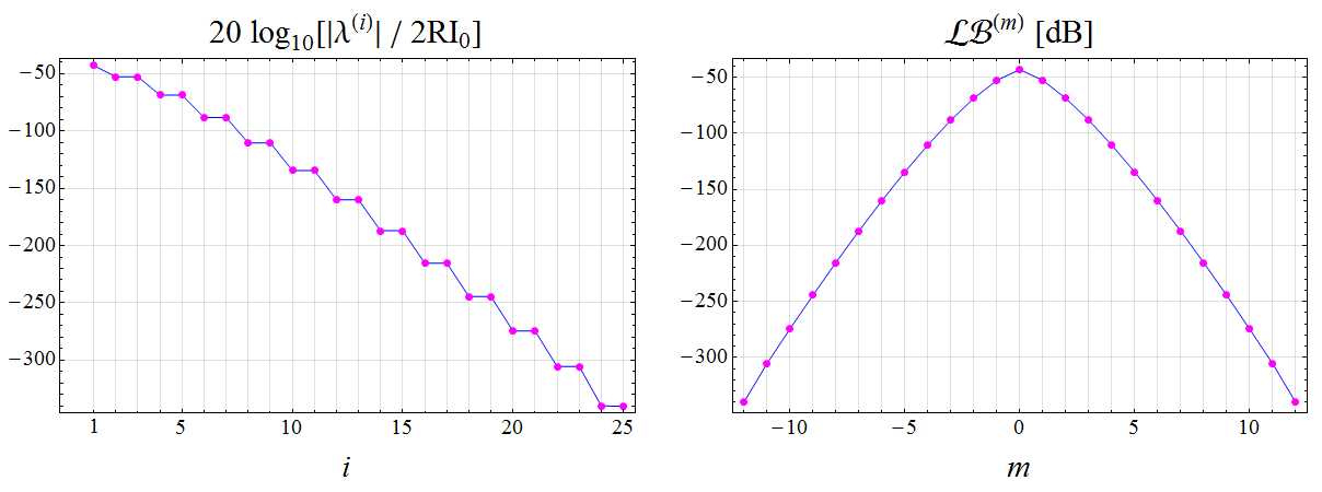
Refer to caption
Figure 16: Comparison between the eigenvalues of (25), expressed in terms of the spectral index i𝑖i (left), and the link budget (43) relative to Hpn(±)superscriptsubscript𝐻𝑝𝑛plus-or-minusH_{pn}^{(\pm)} for the couple of transmitting and receiving beamforming coefficients defined in (79) as a function of the OAM charge m𝑚m (right), for N=25𝑁25N=25, a=λ=1𝑎𝜆1a=\lambda=1 m, l=λ/20𝑙𝜆20l=\lambda/20, d=10λ𝑑10𝜆d=10\lambda.

In Figure 16, a comparison between the eigenvalues distribution of Hpn(±)superscriptsubscript𝐻𝑝𝑛plus-or-minusH_{pn}^{(\pm)} and the corresponding link budget for the communication by vortex waves as a function of m𝑚m is proposed for the same choice of the parameters introduced in the main text. From the comparison we infer how the two-fold degeneracy in the channel matrix spectrum can be traced back to the fact that two communications by vortex waves with opposite charges ±mplus-or-minus𝑚\pm m share the same power level.

Equation (79) tells us that, at least when identical facing UCAs are concerned, the best beamforming weights that should be introduced at the receiver to properly collect an incoming vortex wave are just the complex conjugates of those employed for generating such wave at the transmitting side333The complex conjugation results from the chirality inversion upon reception together with the circumstance that the same orientation direction has been chosen in the labeling of the elements along both the transmitting and the receiving UCAs. A different approach would be to employ an opposite sorting for the two arrays, in which case the complex conjugation is no longer present.. The validity of this result extends far beyond the proposed scenario, in that it represents a natural consequence of the reciprocity theorem.

References

  • [1] Allen L, Barnett S M and Padgett M J 2003 Optical Angular Momentum (Institute of Physics Publishing, Bristol)
  • [2] Andrews D L 2008 Structured Light and Its Applications: An Introduction to Phase-Structured Beams and Nanoscale Optical Forces (Academic Press, Elsevier, USA)
  • [3] Andrews D L and Babiker M 2013 The Angular Momentum of Light (Cambridge University Press)
  • [4] Torres J P and Torner L 2011 Twisted Photons (WILEY-VCH Verlag and Co. KGaA, Weinheim, Germany)
  • [5] Bazhenov V Y, Vasnetsov M V and Soskin M S 1990 Journal of Experimental and Theoretical Physics Letters 52 429–431
  • [6] Beijersbergen M W, Allen L, van der Veen H E L O and Woerdman J P 1993 Optics Communications 96 123–132 URL http://www.sciencedirect.com/science/article/pii/003040189390535D
  • [7] Beijersbergen M W, Coerwinkel R P C, Kristensen M and Woerdman J P 1994 Optics Communications 112 321–327 URL http://www.sciencedirect.com/science/article/pii/0030401894906386
  • [8] Padgett M and Allen L 2000 Contemporary Physics 41 275–285 URL https://doi.org/10.1080/001075100750012777
  • [9] Yao A M and Padgett M J 2011 Adv. Opt. Photon. 3 161–204 URL http://aop.osa.org/abstract.cfm?URI=aop-3-2-161
  • [10] Marrucci L, Karimi E, Slussarenko S, Piccirillo B, Santamato E, Nagali E and Sciarrino F 2011 Journal of Optics 13 URL http://stacks.iop.org/2040-8986/13/i=6/a=064001
  • [11] Marrucci L, Manzo C and Paparo D 2006 Physical Review Letters 96(16) URL https://link.aps.org/doi/10.1103/PhysRevLett.96.163905
  • [12] Berry M V 1987 Journal of Modern Optics 34 1401–1407 URL https://doi.org/10.1080/09500348714551321
  • [13] Barbuto M, Trotta F, Bilotti F and Toscano A 2014 Progress in Electromagnetics Research 148 23–30 URL http://www.jpier.org/PIER/pier.php?paper=14050204
  • [14] Cheng L, Hong W and Hao Z C 2014 Scientific Reports 4 URL https://www.nature.com/articles/srep04814
  • [15] Fonseca N J G, Coulomb L and Angevain J C 2015 A Fresnel-like reflector antenna design for high-order orbital angular momentum states EuCAP 2015 - The 9th European Conference on Antennas and Propagation URL https://ieeexplore.ieee.org/abstract/document/7228413/
  • [16] Maccalli S, Pisano G, Colafrancesco S, Maffei B, Richard Ng M W and Gray M 2013 Applied Optics 52 635–639 URL http://ao.osa.org/abstract.cfm?URI=ao-52-4-635
  • [17] Niemiec R, Brousseau C, Mahdjoubi K, Emile O and Ménard A 2014 IEEE Antennas and Wireless Propagation Letters 13 1011–1014
  • [18] Tennant A and Allen B 2012 Electronics Letters 48 1365–1366
  • [19] Yu S, Li L, Shi G, Zhu C, Zhou X and Shi Y 2016 Applied Physics Letters 108 URL https://doi.org/10.1063/1.4944789
  • [20] Zheng S, Zhang W, Zhang Z, Jin X, Chi H and Zhang X 2016 Photonic Research 4 B9–B13 URL http://www.osapublishing.org/prj/abstract.cfm?URI=prj-4-5-B9
  • [21] Thidé B, Then H, Sjöholm J, Palmer K, Bergman J, Carozzi T D, Istomin Y N, Ibragimov N H and Khamitova R 2007 Phys. Rev. Lett. 99(8) 087701 URL https://link.aps.org/doi/10.1103/PhysRevLett.99.087701
  • [22] Collin R E and Zucker F J 1969 Antenna Theory (McGraw-Hill Book Company, Inc., New York)
  • [23] Orfanidis S J 2016 Electromagnetic Waves and Antennas URL http://www.ece.rutgers.edu/~orfanidi/ewa
  • [24] Chandran S 2004 Adaptive Antenna Arrays (Springer-Verlag, Berlin)
  • [25] Haupt R L 2010 Antenna Arrays (John Wiley and Sons, Inc., Hoboken, New Jersey)
  • [26] Rabinovich V and Alexandrov N 2013 Antenna Arrays and Automotive Applications (Springer Science, Business Media, New York)
  • [27] Abramowitz M and Stegun I A 1972 Handbook of Mathematical Functions 10th ed (Washington, DC: National Bureau of Standards, US Government Printing Office)
  • [28] Volke-Sepulveda K, Garcés-Chávez V, Chávez-Cerda S, Arlt J and Dholakia K 2002 Journal of Optics B: Quantum and Semiclassical Optics 4 S82 URL http://stacks.iop.org/1464-4266/4/i=2/a=373
  • [29] Knudsen H 1956 IRE Transactions on Antennas and Propagation 4 452–472
  • [30] Zhu J, Cai X, Chen Y and Yu S 2013 Optics Letters 38 1343–1345 URL http://ol.osa.org/abstract.cfm?URI=ol-38-8-1343
  • [31] Zhu J, Chen Y, Zhang Y, Cai X and Yu S 2014 Optics Letters 39 4435–4438 URL http://ol.osa.org/abstract.cfm?URI=ol-39-15-4435
  • [32] Born M and Wolf E 1999 Principles of Optics 7th ed (Cambridge University Press)
  • [33] Miller D A B 2000 Applied Optics 39 1681–1699 URL http://ao.osa.org/abstract.cfm?URI=ao-39-11-1681
  • [34] Edfors O and Johansson A J 2012 IEEE Transactions on Antennas and Propagation 60 1126–1131
  • [35] Devaney A J 2012 Mathematical Foundations of Imaging, Tomography and Wavefield Inversion (Cambridge University Press)
  • [36] Jackson J D 1999 Classical Electrodynamics 3rd ed (John Wiley and Sons, Inc., New York)
  • [37] Morse P M and Feshbach H 1953 Methods of Theoretical Physics (McGraw-Hill Book Company, Inc., New York)
  • [38] Golub G H and Van Loan C F 1996 Matrix Computations 3rd ed (The Johns Hopkins University Press, Baltimore)
  • [39] Horn R A and Johnson C R 1994 Topics in Matrix Analysis 2nd ed (Cambridge University Press)
  • [40] Harrington R F 2001 Time-harmonic electromagnetic fields (John Wiley and Sons, Inc., New Jork)