Controlled-phase Gate using Dynamically Coupled Cavities and Optical Nonlinearities
Abstract
We propose an architecture for a high-fidelity deterministic controlled-phase gate between two photonic qubits using bulk optical nonlinearities in near-term feasible photonic integrated circuits. The gate is enabled by converting travelling continuous-mode photons into stationary cavity modes using strong classical control fields that dynamically change the cavity-waveguide coupling rate. This process limits the fidelity degrading noise pointed out by Shapiro [J. Shapiro, Phys. Rev. A, 73, 2006] and Gea-Banacloche [J. Gea-Banacloche, Phys. Rev. A, 81, 2010]. We show that high-fidelity gates can be achieved with self-phase modulation in materials as well as second-harmonic generation in materials. The gate fidelity asymptotically approaches unity with increasing storage time for a fixed duration of the incident photon wave packet. Further, dynamically coupled cavities enable a trade-off between errors due to loss and wave packet distortions since loss does not affect the ability to emit wave packets with the same shape as the incoming photons. Our numerical results show that gates with fidelity are feasible with near-term improvements in cavity loss using LiNbO3 or GaAs.
The quest for determinstic photon-photon logic gates has generally been hindered by the absence of sufficiently strong nonlinearities at optical frequencies. One possible solution is to use detection as an effective nonlinearity [1], but two-qubit gates realized this way are probabilistic and require large resource overheads [2]. Even with large Kerr nonlinearities, Shapiro showed in 2006 that two-photon gates between traveling wave packets cannot achieve high fidelity [3]; this fundamental limit was further elucidated in more recent work [4, 5, 6, 7]. Newer theoretical proposals have re-opened the discussion by showing that arbitrarily high fidelity is possible in certain limits [8, 9, 10], but their implementation appears to be very complex.
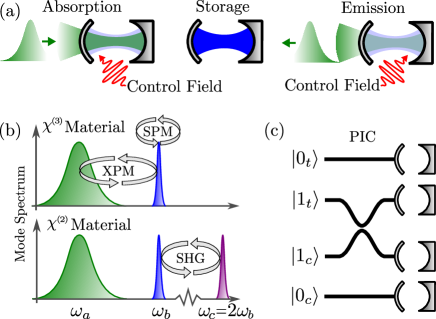
Here, we introduce an approach relying on dynamically coupled cavities to provide a means for absorbing, storing, and re-emitting photons from a multimode nonlinear optical cavity. Classical control fields couple two cavity modes via nonlinear wave mixing with a time-dependent coupling rate determined by the amplitude and phase of the controls. As illustrated in Fig. 1a, incident wave packets couple to cavity mode (green mode) and are transferred to mode (blue mode) via their controlled coupling. Destructive interference between the directly reflected component of the incident wave packet and light leaking out from mode causes complete absorption by adjusting the controlled coupling to transfer population from mode to at the right rate. Photons are then stored in mode , which is decoupled from the waveguide, and subsequent control fields release them through mode . A similar cavity configuration was recently proposed to separate temporal modes of propagating pulses [11].
While stored in the decoupled cavity mode, photons are single-mode in the limit of zero intrinsic cavity loss. The fidelity limitations pointed out in Ref. [3] therefore do not apply to their interaction during this time. However, the control field that optimally absorbs and emits wave packets depends on the photon number when nonlinear interactions are present during the absorption and emission process. Since the same control field must be applied to any input state, it unavoidably introduces a finite amount of error consistent with Refs. [3, 4, 5, 6, 7]. Our numerical analysis reveals that this error scales favorably with the ratio between the storage time, , and the duration of the input wave packet. The result is a scheme for high-fidelity photon-photon gates using bulk nonlinearities that should be feasible with near-term improvements in technology.
For an input state with two dual-rail encoded photonic qubits (see Fig. 1c), we denote the action of the gate by e.g. . Single-photon input states like are fully characterized by their wave packets, , where normalization requires and is the continuous-time annihilation operator of the waveguide. Output wave packets are defined through or corresponding to the input . The controlled-phase operation corresponds to the phase requirement, , and we define the one- and two-photon state fidelities as
| (1a) | ||||
| (1b) | ||||
We consider loss by including a loss rate, , for all cavity modes. The output is therefore in a mixed state but we only calculate the dynamics of the zero-loss subspace where the output states above are not normalized and the fidelity in Eq. (1) is a lower bound [12].
To calculate the output wave packets, we use a Schrödinger-picture version of the established time-bin formalism [13, 14, 15], which allows us to derive explicit equations of motion for the cavity states and input-output relations in terms of the cavity Fock basis. In the time-bin formulation the waveguide field is divided into time-bins of duration , and the cavity interacts with the time bins one after the other. We refer to Ref. [12] for detailed derivations of all the equations of motion and input-output relations used here.
We choose to calculate the controls so single-photon inputs are absorbed optimally into cavity mode . We therefore only need to consider the linear part of the Hamiltonian without photon-photon interaction terms. For the time-step, in which the cavity interacts with time-bin , this Hamiltonian in a rotating frame is
| (2) |
where and are annihilation operators for photons in cavity modes and . The discrete-time annihilation operator of the waveguide in bin is . Its relation to the continuous-time operator is with and . is the cavity-waveguide coupling rate of mode and is the coupling rate between modes and , which is completely determined by the control fields. For materials, arises from four wave mixing between two control fields and modes and . To achieve energy-matching, the carrier frequencies obey the relation , where and are the carrier frequencies of the control fields. For materials, arises from three wave mixing between one control field and modes and . In this case, their frequencies obey , where is the carrier frequency of the control field.
In Ref. [12] we derived solutions for that enable complete absorption of a single photon with an arbitrary wave packet or emission of an arbitrary output, where refers to a material. The solutions differ due to cross-phase modulation imparted on cavity modes and by the control fields only in materials. Fig. 2a shows an example of the absorption process with being a Gaussian centered at with temporal full-width-at-half-maximum and spectral width .
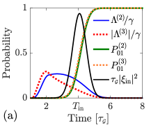
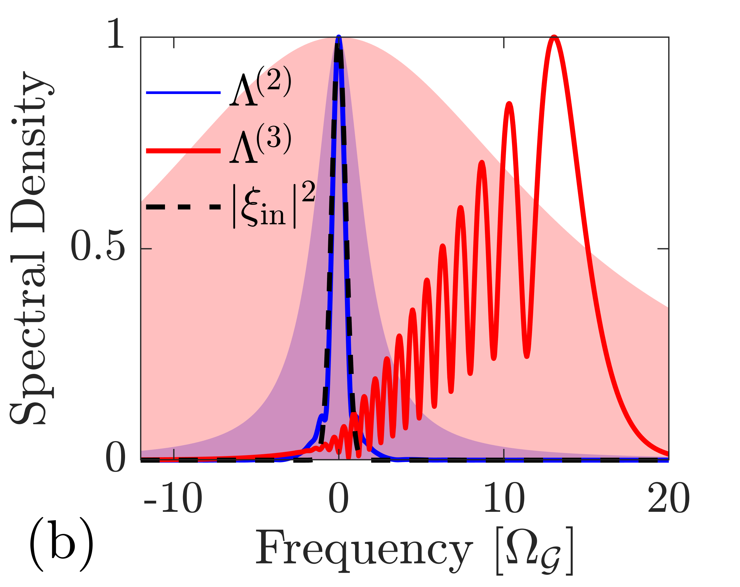
The occupation probability of mode is , where again refers to the order of the nonlinearity. has a time-dependent phase to compensate for the cross-phase modulation it induces on modes and . This broadens and shifts its Fourier spectrum as seen in Fig. 2b. The absence of cross-phase modulation in materials also enables a similar absorption probability with a five times smaller coupling rate, , compared to materials.
The probability of absorbing an incoming wave packet only depends on the ratio between mode ’s linewidth, , and the spectral width of the wave packet, . Fig. 3 plots the error in the one-photon state fidelity, , for a Gaussian wave packet with a storage time of . The different curves correspond to different loss rates, , which is assumed equal for all cavity modes.
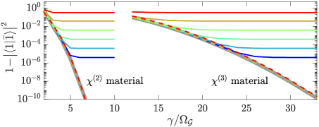
It shows how the error decreases much faster with increasing for materials than materials due to the absence of cross-phase modulation. The curves flatten where the error becomes dominated by loss. Fig. 3 also plots the error in the conditional one-photon state fidelity defined by . may be understood as the probability of the input and output states being identical given there was no loss because it corresponds to the fidelity calculated using the re-normalized state [12].
The ideal scenario for lossy cavities is that the output wave packet is a scaled version of the input, . For a given loss rate, , there is a corresponding value of from which is calculated to achieve , see Ref. [12] for details. Since the conditional fidelity by definition is independent of the scaling factor , we expect it to be negligibly dependent on loss so that , which is confirmed in Fig. 3.
Thus, the photons will exhibit very high visibility quantum interference with other photons in Gaussian wave packets if they are not lost. For increasing loss, it is always possible to achieve such high visibility at the cost of a corresponding decrease in .
The gate fidelity is defined as the minimum state fidelity for all input states [16, 17]. We can ensure that if is large enough, which means that the gate fidelity is given by . Below, we choose for materials and for materials, which is seen to fulfill this requirement from Fig. 3. The Hamiltonian in Eq. (2) describes only the linear dynamics responsible for absorption and emission from the cavity. The nonlinear interactions responsible for the conditional phase shift are described by the Hamiltonians
| (3a) | ||||
| (3b) | ||||
where is the annihilation operator for photons in mode , see Fig. 1b. The nonlinear coupling rates are [18, 19]
| (4) |
where , , is the vacuum permittivity, is the -order nonlinear susceptibility, and is the mode volume for -order interactions.
In materials the conditional phase shift arises due to the self-phase modulation experienced by two photons while stored in mode . In materials a phase shift occurs when two photons undergo one Rabi oscillation between mode and , see Fig. 1b. The storage time is adjusted to ensure that the phase requirement is fulfilled in both cases.
Fig. 4a shows the error, , for a material as a function of storage time for different values of the cavity loss rate, .
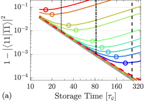
Note that for each storage time, the nonlinear coupling rate, , was chosen to achieve the phase requirement mentioned above. Without loss, the error scales as and 99 % fidelity is possible with . The dashed colored lines in Fig. 4a plot the conditional fidelity, . Note that as in Fig. 3, which means that may be understood as the error resulting from wave packet distortion alone, while additionally includes error from loss. Increasing the storage time (beyond the optimum indicated by circles in Fig. 4a) allows for reduced wave packet distortions at the cost of increased loss, resulting in a trade-off between the two error mechanisms.
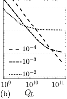
Eq. (4) may be used to convert the normalized loss rate, , into an intrinsic quality factor, . We do this using the parameters listed in the caption of Fig. 4 for a silicon cavity with an ultra-small mode volume [21, 22, 23]. Fig. 4b plots the error, , as a function of for the three vertical cross-sections in Fig. 4a corresponding to three limiting values of the conditional fidelity. The error is dominated by loss where the curves are linear and becomes dominated by wave packet distortion where the curves saturate.
Fig. 5a shows the error, , for a material as a function of storage time for different values of the cavity loss rate. Here, the nonlinear coupling rate, , is adjusted for each to ensure that it corresponds to one Rabi oscillation of the SHG process.
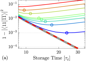
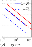
The error-scaling is , which is better than in Fig. 4a since the photons only interact when they are both in mode , while they interact during the entire absorption and emission process through both cross- and self-phase modulation for materials. For the optimum choice of (indicated by circles in Figs. 4a and 5a), the error grows in proportion to the ratio between the loss rate and the nonlinear coupling, , where again denotes the order of the nonlinear interaction. Fig. 5b plots this relationship for both (blue) and materials (red). It also shows that the conditional error, , follows the same relation but is 5.1 and 3.0 times smaller (dashed lines) for and materials, respectively. The error may then be related to the quality factor and mode volume by
| (5) |
where and . Table 1 lists the values of for the two most promising materials and the most common material, silicon. The table also lists the required intrinsic quality factor to achieve a conditional fidelity of 99% for an ultra-small mode volume, [21, 22, 23], and a standard size for one-dimensional photonic crystal cavities, .
| LiNbO3 | GaAs | Si | ||||
| 0.5 | 0.5 | 0.5 | ||||
The numbers seem prohibitively large for materials, but for they are close to state-of-the-art s in LiNbO3, for which has been demonstrated in ring resonators both at telecom [26] and visible wavelengths [27] and in photonic crystal cavities [28, 29]. The large difference between and is primarily due to the difference in nonlinear coupling rates in Eq. (4), but there is also a contribution from the difference between and in Fig. 5b.
Our results show that dynamically coupled cavities offer a very promising approach to realize determinstic two-qubit gates between photons in a dual-rail encoding. With recent progress in nanofabrication of LiNbO3 PICs [26, 28, 29] and development of ultra-confined photonic crystal cavities [21, 22, 23] it appears that experimental demonstrations are within reach. Recent theoretical work also promises the required spectral properties of cavities [30]. Noise sources not included in our analysis must also be investigated, including thermal noise-photons or photons generated by the control fields as well as higher-order nonlinear effects - in particular -effects in materials.
We acknowledge that experimental implementations remain very challenging, but hope it will stimulate the necessary near-term experimental advances to enable deterministic, high-fidelity photonic logic gates as well as extensions such as encoded logical qubits for quantum computing and one-way quantum repeaters.
Acknowledgments: The authors thank Joshua Combes and Jeffrey Shapiro for many useful discussions. This work was partly funded by the AFOSR program FA9550-16-1-0391, supervised by Gernot Pomrenke (D. E.), the MITRE Quantum Moonshot Program (M. H. and D. E.), the ARL DIRA ECI grant “Photonic Circuits for Compact (Room-temperature) Nodes for Quantum Networks” (K. J.), and The Velux Foundations (M. H.).
References
- Knill et al. [2001] E. Knill, G. Milburn, and R. Laflamme, A scheme for efficient quantum computation with linear optics, Nature 409, 46 (2001), arXiv:arXiv:1208.4575v2 .
- Kok et al. [2007] P. Kok, K. Nemoto, T. C. Ralph, J. P. Dowling, and G. J. Milburn, Linear optical quantum computing with photonic qubits, Reviews of Modern Physics 79, 135 (2007).
- Shapiro [2006] J. Shapiro, Single-photon Kerr nonlinearities do not help quantum computation, Physical Review A 73, 062305 (2006).
- Gea-Banacloche [2010] J. Gea-Banacloche, Impossibility of large phase shifts via the giant Kerr effect with single-photon wave packets, Physical Review A 81, 043823 (2010).
- He et al. [2011] B. He, A. MacRae, Y. Han, A. I. Lvovsky, and C. Simon, Transverse multimode effects on the performance of photon-photon gates, Physical Review A 83, 1 (2011).
- Xu et al. [2013] S. Xu, E. Rephaeli, and S. Fan, Analytic properties of two-photon scattering matrix in integrated quantum systems determined by the cluster decomposition principle, Physical Review Letters 111, 1 (2013).
- Dove et al. [2014] J. Dove, C. Chudzicki, and J. H. Shapiro, Phase-noise limitations on single-photon cross-phase modulation with differing group velocities, Physical Review A 90, 1 (2014), 1410.0663 .
- Ralph et al. [2015] T. C. Ralph, I. Söllner, S. Mahmoodian, A. G. White, and P. Lodahl, Photon Sorting, Efficient Bell Measurements, and a Deterministic Controlled-Z Gate Using a Passive Two-Level Nonlinearity, Physical Review Letters 114, 173603 (2015).
- Brod and Combes [2016] D. J. Brodand J. Combes, Passive cphase gate via cross-kerr nonlinearities, Phys. Rev. Lett. 117, 1 (2016).
- Viswanathan and Gea-Banacloche [2018] B. Viswanathanand J. Gea-Banacloche, Analytical results for a conditional phase shift between single-photon pulses in a nonlocal nonlinear medium, Phys. Rev. A 97, 1 (2018).
- Reddy and Raymer [2018] D. V. Reddyand M. G. Raymer, Photonic temporal-mode multiplexing by quantum frequency conversion in a dichroic-finesse cavity, Opt. Express 26, 28091 (2018).
- Heuck et al. [2019] M. Heuck, K. Jacobs, and D. R. Englund, Photon-Photon Interactions in Dynamically Coupled Cavities, arXiv , 1 (2019), arXiv:1905.02134 .
- Scarani et al. [2002] V. Scarani, M. Ziman, P. Štelmachovič, N. Gisin, and V. Bužek, Thermalizing quantum machines: Dissipation and entanglement, Physical Review Letters 88, 097905 (2002).
- Ciccarello [2017] F. Ciccarello, Collision models in quantum optics, Quantum Measurements and Quantum Metrology 4, 53 (2017).
- Gross et al. [2018] J. A. Gross, C. M. Caves, G. J. Milburn, and J. Combes, Qubit models of weak continuous measurements: markovian conditional and open-system dynamics, Quantum Science and Technology 3, 024005 (2018).
- Nielsen and Chuang [2011] M. A. Nielsenand I. L. Chuang, Quantum Computation and Quantum Information: 10th Anniversary Edition, 10th ed. (Cambridge University Press, New York, NY, USA, 2011).
- Nysteen et al. [2017] A. Nysteen, D. P. S. McCutcheon, M. Heuck, J. Mørk, and D. R. Englund, Limitations of two-level emitters as nonlinearities in two-photon controlled-PHASE gates, Physical Review A 95, 1 (2017), arXiv:1612.04803 .
- Majumdar and Gerace [2013] A. Majumdarand D. Gerace, Single-photon blockade in doubly resonant nanocavities with second-order nonlinearity, Physical Review B - Condensed Matter and Materials Physics 87, 1 (2013).
- Vernon and Sipe [2015] Z. Vernonand J. E. Sipe, Strongly driven nonlinear quantum optics in microring resonators, Physical Review A - Atomic, Molecular, and Optical Physics 92, 1 (2015).
- Moss et al. [2013] D. J. Moss, R. Morandotti, A. L. Gaeta, and M. Lipson, New CMOS-compatible platforms based on silicon nitride and Hydex for nonlinear optics, Nature Photonics 7, 597 (2013).
- Hu and Weiss [2016] S. Huand S. M. Weiss, Design of Photonic Crystal Cavities for Extreme Light Concentration, ACS Photonics , acsphotonics.6b00219 (2016).
- Choi et al. [2017] H. Choi, M. Heuck, and D. Englund, Self-Similar Nanocavity Design with Ultrasmall Mode Volume for Single-Photon Nonlinearities, Physical Review Letters 118, 10.1103/PhysRevLett.118.223605 (2017).
- Hu et al. [2018] S. Hu, M. Khater, R. Salas-Montiel, E. Kratschmer, S. Engelmann, W. M. J. Green, and S. M. Weiss, Experimental Realization of Deep Subwavelength Confinement in Dielectric Optical Resonators, Science Advances 4 (2018), arXiv:1707.04672 .
- Wang et al. [2017] C. Wang, X. Xiong, N. Andrade, V. Venkataraman, X.-F. Ren, G.-C. Guo, and M. Lončar, Second harmonic generation in nano-structured thin-film lithium niobate waveguides, Optics Express 25, 6963 (2017).
- Skauli et al. [2002] T. Skauli, K. L. Vodopyanov, T. J. Pinguet, A. Schober, O. Levi, L. A. Eyres, M. M. Fejer, J. S. Harris, B. Gerard, L. Becouarn, E. Lallier, and G. Arisholm, Measurement of the nonlinear coefficient of orientation-patterned GaAs and demonstration of highly efficient second-harmonic generation, Optics Letters 27, 628 (2002).
- Zhang et al. [2017] M. Zhang, C. Wang, R. Cheng, A. Shams-Ansari, and M. Lončar, Monolithic ultra-high-q lithium niobate microring resonator, Optica 4, 1536 (2017).
- Desiatov et al. [2019] B. Desiatov, A. Shams-ansari, M. Zhang, C. Wang, and M. Loncar, Ultra-low loss integrated visible photonics using thin-film lithium niobate, arXiv , 1 (2019), arXiv:arXiv:1902.08217v1 .
- Liang et al. [2017] H. Liang, R. Luo, Y. He, H. Jiang, and Q. Lin, High-quality lithium niobate photonic crystal nanocavities, Optica 4, 1251 (2017), arXiv:1706.08904 .
- Lin [2019] Q. Lin, Integrated photonic devices for controlling quantum properties of light, Photonics for Quantum workshop at Rochester Institute of Technology, January (2019), https://www.rit.edu/fpi/photonics-quantum-pfq-workshop#program.
- Minkov et al. [2019] M. Minkov, D. Gerace, and S. Fan, Doubly resonant nonlinear photonic crystal cavity based on a bound state in the continuum, Optica 6, 1039 (2019).