Bias induced spin state transition mediated by electron excitations
Abstract
Recent experiments reported that spin-state transitions were realized by applying bias voltages. But these bias-induced spin state transitions (BISSTs) are not fully understood, especially the mechanism. It is well known that the metal-to-ligand charge transfer excitation (MLCT) and the metal-centered excitation (MC) activated by light radiation can induce the transition from low spin (LS) to high spin (HS) and that from HS to LS. Moreover, electronic excitations are accessible by inelastic cotunneling in molecular junctions with bias voltages applied. Based on these two experimental facts, we propose the MLCT basically leads to the BISST from LS to HS, and the MC results in the BISST from HS to LS. The rationality of the mechanism is demonstrated by comparing first-principles results and experimental observations. The calculated voltage threshold for activating the MLCT (MC) is close to the experimental voltage for observing the BISST from LS to HS (from HS to LS). The activation of MLCT (MC) depends on the bias polarity, which can explain the bias-polarity dependence of BISST in the experiment. Our study is important for further design of molecular spintronic devices working on spin state transition.
pacs:
I Introduction
On the molecular scale manipulation of spin by electrical means is attractive and important, especially for molecular spintronic devicesSanvito (2011); Rocha et al. (2005); Bogani and Wernsdorfer (2008). Such a manipulation is simpler and of higher spatial resolution than that by other means (e.g. temperature, pressure, light and magnetic field), which helps to simplify the architecture of devices and increase the density of functional units. Recent experiments reported that spin crossover molecules can be used to achieve the spin state transition (SST) by applying bias voltages in molecular junctionsPrins et al. (2011); Miyamachi et al. (2012); Gopakumar et al. (2012). The involved molecules have a nearly octahedral structure in which one ferrous ion of is surrounded by several organic ligands. The ground (metastable) state is related to a low-spin (high-spin) metal ionGütlich, Hauser, and Spiering (1994); Bousseksou et al. (2011). The switch between the low-spin ground state and the high-spin metastable state is accompanied by a great change in electron transport propertyHuang et al. (2016); Aravena and Ruiz (2012); Baadji and Sanvito (2012) and optics (a pronounced, visible change of colour)Kahn and Martinez (1998). Consequently, spin crossover molecules and the related bias-induced SST (or BISST) have greatly potential applications in molecular switches, molecular transistors, molecular memory devices, display devices, etcLétard, Guionneau, and Goux-Capes (2004).
In spite of the above achievements, the BISST is not fully understood, especially its mechanism. Several possibilities were suggested to explain the BISST from low spin (LS) to high spin (HS). For example, local resistive heating or the Joule effect (due to inelastic scattering of tunneling electrons) may trigger the BISST from LS to HSMiyamachi et al. (2012); Prins et al. (2011). This BISST may be caused by the Stark effectDiefenbach and Kim (2007); Baadji et al. (2009); Hao et al. (2012). However, it is observed that the BISST from LS to HS depends on the bias polarity in experiments, that is, it can be achieved only by applying negative bias voltages to the molecular junction but not by positive bias voltagesMiyamachi et al. (2012), or vice versaGopakumar et al. (2012). In view of this feature, the Joule-heat mechanism is hardly responsible for the BISST from LS to HS because the inelastic scattering of tunneling electrons is present at both bias polarities. For the similar reason, the Stark effect is not the cause for the BISST as well, which has been confirmed by the experimentGopakumar et al. (2012). In addition, our previous workHao et al. (2017) suggested the BISST from LS to HS stimulated by one electron added to the molecule. Based on this mechanism, one can comprehend the BISST dependent on the bias polarity, but the voltage threshold is much larger than the experimental voltage for observing the BISSTMiyamachi et al. (2012). As for the BISST from HS to LS, Miyamachi et al. (2012) guessed that it is closely related to the - transition, but this mechanism has not been confirmed until now, and its dependence on the bias polarity has been also unclear.
In the present work, we propose that the metal-to-ligand charge transfer excitation (MLCT) basically causes the BISST from LS to HS, and the metal-centered excitation (MC) or - transition triggers the BISST from HS to LS. Our proposed mechanism is based on two well-established facts in experiments. One is that the light-induced MLCT and MC can generate the SST from LS to HSChergui (2013) and that from HS to LSHauser (1995); Gütlich, Garcia, and Goodwin (2000), which is commonly called the light-induced excited spin state trapping (LIESST). The other is that electronic excitations including MLCT and MC can be stimulated by the inelastic electron cotunneling through molecules, which is a two-electron tunneling process in the Coulomb blockade regionDe Franceschi et al. (2001); Osorio et al. (2008). To show the rationality of our proposed mechanism, time-dependent density-functional theory (TD-DFT) calculations are performed and the molecule \ceFe(phen)2(NCS)2 (\cephen=1,10-phenanthroline) is taken as example. The calculated voltage threshold for activating MLCT (MC) is close to the bias voltage used to observe the BISST from LS to HS (from HS to LS) in the experimentMiyamachi et al. (2012). Moreover, it is revealed that the activation of MLCT (MC) is determined by the bias polarity, which can explain the bias-polarity dependence of BISST from LS to HS (from HS to LS).
II Computational details
The spin crossover molecule \ceFe(phen)2(NCS)2 is taken as example because it is involved in a scanning tunneling microscopy (STM) experimentMiyamachi et al. (2012), where the bias-polarity dependence of BISST is observed and bias voltages used to observe the BISST between LS and HS are well recorded. The other optical experiment based on the same molecule shows the MLCT is responsible for the transition from LS to HS, and the MLCT (MC) energy is recognizedBertoni et al. (2015). These help to verify our calculation method and the rationality of our proposed mechanism. In \ceFe(phen)2(NCS)2, the ferrous ion with is in the center of a nearly octahedral structure and surrounded by two different kinds of ligands (\ceNCS and \cephen). orbitals of the ferrous ion are split into two higher-level \cee_g and three lower-level \cet_2g orbitals. The electron configuration in the high-spin state is \cet^4_2g\cee^2_g, and that in the low-spin state is \cet^6_2g\cee^0_g. Our study is based on the free or gas-phase molecule since the couplings of the molecule with the tip and substrate are generally quite weak in experimentsMiyamachi et al. (2012); Prins et al. (2011); Gopakumar et al. (2012), and electronic structures are little affected by metallic electrodesGueddida and Alouani (2013). To optimize the structure, the B3LYP functional along with the 6-31G(d) basis set is employed in unrestricted open-shell calculations. This combination usually yields reliable ground-state geometries. We use the PBE0 functionalAdamo and Barone (1999) and the 6-311G(d,p) basis set to calculate excitation energies of the considered molecule, and results agree well with optical observationsBertoni et al. (2015); De et al. (2018); Glijer et al. (2008); Buron-Le Cointe et al. (2012); Hauser (1986, 1991); Romstedt, Hauser, and Spiering (1998). The spin multiplicity of the excited state is the same as that of the ground state for both high-spin and low-spin molecules. All calculations are performed using Gaussian09Frisch et al. .
III Results and discussion
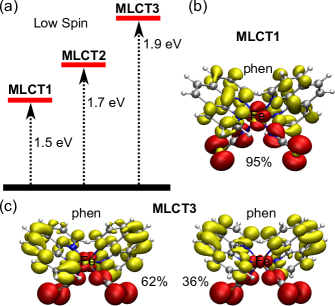
Firstly, we focus on the MLCT in the low-spin state. The calculated voltage threshold for stimulating the lowest MLCT is found to be consistent with bias voltages inducing the BISST from LS to HS in the experimentMiyamachi et al. (2012). Besides, the realization of MLCT is affected by the bias polarity, which can explain why the BISST from LS to HS is observed only at negative bias in the experiment. These two results support the lowest MLCT leading to the BISST from LS to HS. Details are in the following.
Fig. 1 (a) shows the lowest MLCT (MLCT1) is eV higher than the ground state, and the other two MLCTs are eV (MLCT2) and eV (MLCT3) higher. Features of these three MLCTs are analyzed using the natural transition orbital (NTO) methodMartin (2003). Taking MLCT1 as an example, the hole NTO has an obvious \cet_2g character of the metal ion and the particle NTO is characterized by orbitals of two (\cephen) ligands, as displayed in Fig. 1 (b). According to the NTO theory, an electronic excitation is depicted by transitions from hole NTOs to particle NTOs, thus this excitation is regarded as a MLCT. The percentage () indicates that MLCT1 is determined by one pair of hole and particle NTOs. The MLCT feature is similarly present at MLCT2 and MLCT3, but there are two pairs of hole and particle NTOs contributing to them [see Fig. 1 (c)]. The NTOs of MLCT2 are not shown here. Our calculated energy of MLCT3 is consistent with the optical observationBertoni et al. (2015), where a MLCT of \ceFe(phen)2(NCS)2 is detected by the pump light at nm ( eV). Other optical experimentsDe et al. (2018); Glijer et al. (2008); Buron-Le Cointe et al. (2012) demonstrate that a MLCT can be attained by an infrared radiation (around nm or eV), close to the calculated energy of MLCT1. Hence, our calculation based on PBE0/6-311G(d,p) is reliable to study the MLCT of the considered molecule.
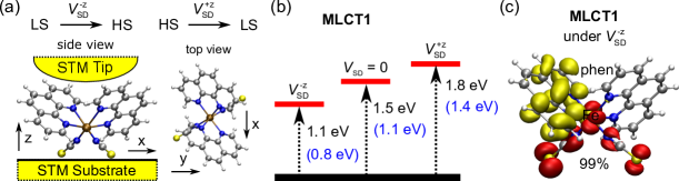
To accurately depict the MLCT in the BISST experimentMiyamachi et al. (2012), it is necessary to consider the effect of couplings with the STM substrate and that of bias voltages on excitations. As for couplings with the STM substrate, Gueddida and Alouani has clearly demonstrated when the low-spin molecule is absorbed on the STM substrate [CuN/Cu(001)] in the experiment, its electronic structure is almost the same as that in the free caseGueddida and Alouani (2013). Thus for simplicity, the free molecule is used to simulate excitations in the molecular junction. Additionally, the BISST from LS to HS is observed by applying negative bias voltages to the substrate but not by positive bias voltages in the experiment, schematically displayed in Fig. 2 (a). To consider the effect of the negative bias voltage, we apply an uniform electrostatic field with a moderate magnitude of V/Å (marked by ) to the molecule, and is along the direction opposite to z in Fig. 2 (a). Then Fig. 2 (b) shows the energy of MLCT1 is decreased from to eV with applied. The lowered energy of MLCT1 is because the electric dipole moment induced by the hole-particle transition in Fig. 1 (b) (or transition dipole moment) has the same direction with the electrostatic field and MLCT1 is favored by the negative bias. It has been known that an excitation can be achieved by inelastic cotunneling only if is satisfiedDe Franceschi et al. (2001); Osorio et al. (2008), where is the applied bias voltage and is the energy of this excitation relative to the ground state. Accordingly, the voltage threshold for activating MLCT1 is V in this case, which coincides with the experiment that the BISST from LS to HS can be observed by applying a negative bias voltage of V. Moreover, the negative bias voltage inducing the BISST from LS to HS can further decrease to V in the experiment. This bias voltage is probably because of the structural relaxation of MLCT1. After considering both the structural relaxation and , our calculated energy of MLCT1 is also reduced to eV [marked by parenthesis in Fig. 2 (b)], which is still consistent with the experiment. The NTO analysis in Fig. 2 (c) exhibits the MLCT feature of MLCT1 when these two factors are taken into account. In summary, the calculated voltage threshold for activating MLCT1 agrees well with bias voltages used to observe the BISST from LS to HS in the experiment.
Here, we will illustrate MLCT1 becomes unaccessible at positive bias. For this purpose, we calculate the energy of MLCT1 under with the magnitude of V/Å. is used to simulate the effect of the positive bias voltage, and is along the z direction [see Fig. 2 (a)]. Based on this model, the energy of MLCT1 is increased from to eV [Fig. 2 (b)], and the energy is still as high as eV even further including the structural relaxation. Owing to the increased energy, MLCT1 becomes hardly accessible by the positive bias voltage ( V) in the experiment, and the transition from LS to HS mediated by MLCT is not observable. This result is consistent with the absent BISST from LS to HS at positive bias in the experiment.
Secondly, we focus on the MC or transition in the high-spin state. The calculation illustrates the voltage threshold for activating the MC is consistent with bias voltages inducing the BISST from HS to LS in the experimentMiyamachi et al. (2012). Moreover, the MC is prominently observed only at positive bias, which can explain why the BISST from HS to LS is achieved only at positive bias in the experiment. These results support the MC or transition responsible for the BISST from HS to LS.
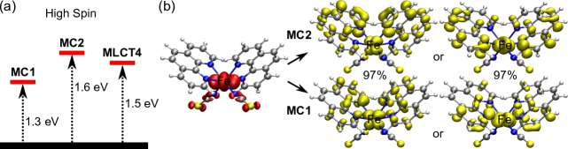
Fig. 3 (a) shows the two lowest MC levels (MC1 and MC2) are respectively and eV higher than the ground state. For each MC level, there are two degenerate excitations, which are from the same \cet_2g-like orbital to two different \cee_g-like orbitals [see Fig. 3 (b)]. The energy difference between MC1 and MC2 is due to different orbitals of the \cephen ligands mixed into transitions. In an optical experimentBertoni et al. (2015), a MC is observed using the probe light at nm ( eV), close to the energy of MC2. Other optical experimentsHauser (1986, 1991); Romstedt, Hauser, and Spiering (1998) demonstrate that there is an obvious MC absorption band ranging from \cecm^-1 ( eV) to \cecm^-1 ( eV). These means our calculation based on PBE0/6-311G(d,p) is reliable to study the MC of the considered molecule as well.
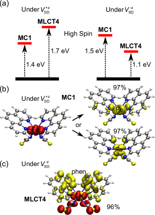
To well describe the MC in the experiment, the effect of couplings with the STM substrate and that of bias voltages should be similarly taken into account. It has been proven when the high-spin molecule is absorbed on the STM substrate [CuN/Cu(001)], its electronic structure is quite close to that in the free (gas) phaseGueddida and Alouani (2013). Hence, the free molecule is still a good model for simulating excitations of the high-spin molecule in the STM experiment. Moreover, the BISST from HS to LS is observed at positive bias in the experiment, and thus we apply the same to the molecule for simulating the effect of the positive bias (vide supra). Fig. 4 (a) displays the energy of MC1 is eV with applied, close to that ( eV) without . The little influenced energy of MC1 is because the - transition just occurs on the metal ion and the induced transition dipole moment is ignorable. The NTO analysis of MC1 in Fig. 4 (b) reveals that orbitals of ligands mixed into MC1 are greatly reduced in both hole and particle NTOs, and the - transition is purified at positive bias. The above result means the voltage threshold for activating a MC is about V, consistent with the experiment that a positive bias voltage of V induces the BISST from HS to LS. In the experiment, it is also found the positive bias voltage inducing the BISST from HS to LS can decrease to V, less than our calculated voltage threshold. To understand this bias voltage, we note an experiment in which hot electrons injected from the STM tip are laterally transported via surface resonances at the metallic surface and the dissociation of the molecule is observedMaksymovych et al. (2007). This dissociation effect is highly possible in the BISST experimentMiyamachi et al. (2012), since the electron tunneling is similarly from the STM tip to the substrate at positive bias [Fig. 2 (a)]. Due to the dissociation effect, the energy gap is decreased between \cet_2g and \cee_g orbitals, and the - transition energy is reduced from V to a lower value. In short, the voltage threshold for activating a MC agrees well with bias voltages used to observe the BISST from HS to LS in the experiment.
For effective access to the MC in the experiment, the applied voltage should be equal to or larger than a related voltage threshold, which is just one hand. The other hand is associated with the bias polarity. When (simulating ) is applied to the considered molecule, the energy of MC1 is eV and the lowest MLCT of the high-spin molecule (MLCT4) is reduced from eV to eV [see Fig. 3 (a) and Fig. 4 (a)]. The MLCT feature of MLCT4 is confirmed by analyzing NTOs in Fig. 4(c), and the MC feature of MC1 at negative bias is similar to that at positive bias [Fig. 4 (b)], thus it is not shown here. It indicates not only MC1 but also MLCT4 are accessible at negative bias ( V) in the experiment. Nonetheless, the oscillator strength of MLCT4 () is greatly higher than that of MC1 (), which is also confirmed by experimentsHauser (2004). Therefore, MLCT4 is predominantly observed at negative bias although both MC and MLCT are accessible. When (simulating ) is applied to the molecule, the energy of MC1 can be reduced to eV in the experiment, but the energy of MLCT4 is as high as eV. Only MC1 can be accessed by the positive bias ( V) in the experiment. The above results illustrate the effective access to the MC is dependent on the bias polarity, which can explain the bias-polarity dependence of the BISST from HS to LS in the experiment.
Finally, based on our present study one could expect that the SST is achieved fast by applying bias voltages in molecular junctions. The fast BISST is due to the SST caused by MLCT and MC, similar to the LIESST. It has been revealed that the SST is observed less than one picosecond following these excitationsBertoni et al. (2015). Additionally, one could anticipate that the bias-polarity dependence of the BISST (LSHS) is easily observed using spin crossover molecules with two different kinds of ligands surrounding the metal ion. Using \ceFe(bpz)2(phen) [bpz=dihydrobis(pyrazoly)borate], Gopakumar et al. (2012) have demonstrated the bias-polarity dependence of the BISST from LS to HS as well.
IV Conclusions
In this paper, we propose that the BISST from LS to HS (or from HS to LS) can be accomplished by MLCT (or MC). This proposal is based on the two facts well established in experiments: i) the SST from LS to HS (from HS to LS) is observed following the light-induced MLCT (MC); ii) electronic excitations including the MLCT and MC can be activated by inelastic electron cotunneling in molecular junctions with bias voltages applied. To show the rationality of our proposal, TD-DFT calculations are performed. The calculated voltage threshold for stimulating the MLCT (MC) is consistent with bias voltages used to observe the BISST from LS to HS (from HS to LS) in the experiment reported by Miyamachi et al. (2012); the realization of MLCT (MC) is determined by the bias polarity, based on which one can well comprehend the bias-polarity dependence of the BISST between LS and HS in the experiment. Our present work helps to design of molcular devices with fast BISST and the special bias-polarity dependence.
Acknowledgement
This work was supported by the National Science Foundation of China under Grant Nos. 11374301, 11774349, 11574318, 11534012, and Director Grants of CASHIPS. Calculations were performed partly at the Center for Computational Science of CASHIPS and partly at the Center for Research Computing at the University of Pittsburgh and the Extreme Science and Engineering Discovery Environment (XSEDE).
References
- Sanvito (2011) S. Sanvito, Chem. Soc. Rev. 40, 3336 (2011).
- Rocha et al. (2005) A. R. Rocha, V. M. García-suárez, S. W. Bailey, C. J. Lambert, J. Ferrer, and S. Sanvito, Nat. Mater. 4, 335 (2005).
- Bogani and Wernsdorfer (2008) L. Bogani and W. Wernsdorfer, Nat. Mater. 7, 179 (2008).
- Prins et al. (2011) F. Prins, M. Monrabal-Capilla, E. A. Osorio, E. Coronado, and H. S. J. van der Zant, Adv. Mater. 23, 1545 (2011).
- Miyamachi et al. (2012) T. Miyamachi, M. Gruber, V. Davesne, M. Bowen, S. Boukari, L. Joly, F. Scheurer, G. Rogez, T. K. Yamada, P. Ohresser, E. Beaurepaire, and W. Wulfhekel, Nat. Commun. 3, 938 (2012).
- Gopakumar et al. (2012) T. G. Gopakumar, F. Matino, H. Naggert, A. Bannwarth, F. Tuczek, and R. Berndt, Angew. Chem. Int. Ed. 51, 6262 (2012).
- Gütlich, Hauser, and Spiering (1994) P. Gütlich, A. Hauser, and H. Spiering, Angew. Chem. Int. Ed. 33, 2024 (1994).
- Bousseksou et al. (2011) A. Bousseksou, G. Molnár, L. Salmon, and W. Nicolazzi, Chem. Soc. Rev. 40, 3313 (2011).
- Huang et al. (2016) J. Huang, R. Xie, W. Wang, Q. Li, and J. Yang, Nanoscale 8, 609 (2016).
- Aravena and Ruiz (2012) D. Aravena and E. Ruiz, J. Am. Chem. Soc. 134, 777 (2012).
- Baadji and Sanvito (2012) N. Baadji and S. Sanvito, Phys. Rev. Lett. 108, 217201 (2012).
- Kahn and Martinez (1998) O. Kahn and C. J. Martinez, Science 279, 44 (1998).
- Létard, Guionneau, and Goux-Capes (2004) J.-F. Létard, P. Guionneau, and L. Goux-Capes, Top. Curr. Chem. 235, 221 (2004).
- Diefenbach and Kim (2007) M. Diefenbach and K. S. Kim, Angew. Chem. Int. Ed. 46, 7640 (2007).
- Baadji et al. (2009) N. Baadji, M. Piacenza, T. Tugsuz, F. D. Sala, G. Maruccio, and S. Sanvito, Nat. Mater. 8, 813 (2009).
- Hao et al. (2012) H. Hao, X. Zheng, L. Song, R. Wang, and Z. Zeng, Phys. Rev. Lett. 108, 017202 (2012).
- Hao et al. (2017) H. Hao, T. Jia, X. Zheng, and Z. Zeng, Phys. Chem. Chem. Phys. 19, 7652 (2017).
- Chergui (2013) M. Chergui, in Spin-Crossover Materials: Properties and Applications, edited by M. A. Halcrow (John Wiley & Sons, Ltd., 2013) Chap. 15.
- Hauser (1995) A. Hauser, Comments on Inorganic Chemistry 17, 17 (1995).
- Gütlich, Garcia, and Goodwin (2000) P. Gütlich, Y. Garcia, and H. A. Goodwin, Chem. Soc. Rev. 29, 419 (2000).
- De Franceschi et al. (2001) S. De Franceschi, S. Sasaki, J. M. Elzerman, W. G. van der Wiel, S. Tarucha, and L. P. Kouwenhoven, Physical Review Letters 86, 878 (2001).
- Osorio et al. (2008) E. A. Osorio, T. Bjørnholm, J.-M. Lehn, M. Ruben, and H. S. J. van der Zant, Journal of Physics: Condensed Matter 20, 374121 (2008).
- Bertoni et al. (2015) R. Bertoni, M. Cammarata, M. Lorenc, S. F. Matar, J.-F. Létard, H. T. Lemke, and E. Collet, Accounts of Chemical Research 48, 774 (2015).
- Gueddida and Alouani (2013) S. Gueddida and M. Alouani, Physical Review B 87, 144413 (2013).
- Adamo and Barone (1999) C. Adamo and V. Barone, The Journal of Chemical Physics 110, 6158 (1999).
- De et al. (2018) S. De, L.-M. Chamoreau, H. El Said, Y. Li, A. Flambard, M.-L. Boillot, S. Tewary, G. Rajaraman, and R. Lescouëzec, Frontiers in Chemistry 6, 326 (2018).
- Glijer et al. (2008) D. Glijer, J. Hébert, E. Trzop, E. Collet, L. Toupet, H. Cailleau, G. S. Matouzenko, H. Z. Lazar, J. F. Létard, S. Koshihara, and M. Buron-Le Cointe, Physical Review B 78, 134112 (2008).
- Buron-Le Cointe et al. (2012) M. Buron-Le Cointe, J. Hébert, C. Baldé, N. Moisan, L. Toupet, P. Guionneau, J. F. Létard, E. Freysz, H. Cailleau, and E. Collet, Physical Review B 85, 064114 (2012).
- Hauser (1986) A. Hauser, Chemical Physics Letters 124, 543 (1986).
- Hauser (1991) A. Hauser, The Journal of Chemical Physics 94, 2741 (1991).
- Romstedt, Hauser, and Spiering (1998) H. Romstedt, A. Hauser, and H. Spiering, Journal of Physics and Chemistry of Solids 59, 265 (1998).
- (32) M. J. Frisch, G. W. Trucks, H. B. Schlegel, G. E. Scuseria, M. A. Robb, J. R. Cheeseman, G. Scalmani, V. Barone, B. Mennucci, G. A. Petersson, H. Nakatsuji, M. Caricato, X. Li, H. P. Hratchian, A. F. Izmaylov, J. Bloino, G. Zheng, J. L. Sonnenberg, M. Hada, M. Ehara, K. Toyota, R. Fukuda, J. Hasegawa, M. Ishida, T. Nakajima, Y. Honda, O. Kitao, H. Nakai, T. Vreven, J. A. Montgomery, Jr., J. E. Peralta, F. Ogliaro, M. Bearpark, J. J. Heyd, E. Brothers, K. N. Kudin, V. N. Staroverov, R. Kobayashi, J. Normand, K. Raghavachari, A. Rendell, J. C. Burant, S. S. Iyengar, J. Tomasi, M. Cossi, N. Rega, J. M. Millam, M. Klene, J. E. Knox, J. B. Cross, V. Bakken, C. Adamo, J. Jaramillo, R. Gomperts, R. E. Stratmann, O. Yazyev, A. J. Austin, R. Cammi, C. Pomelli, J. W. Ochterski, R. L. Martin, K. Morokuma, V. G. Zakrzewski, G. A. Voth, P. Salvador, J. J. Dannenberg, S. Dapprich, A. D. Daniels, . Farkas, J. B. Foresman, J. V. Ortiz, J. Cioslowski, and D. J. Fox, “Gaussian 09 Revision D.01,” Gaussian Inc. Wallingford CT 2009.
- Martin (2003) R. L. Martin, The Journal of Chemical Physics 118, 4775 (2003).
- Maksymovych et al. (2007) P. Maksymovych, D. B. Dougherty, X.-Y. Zhu, and J. T. Yates, Physical Review Letters 99, 016101 (2007).
- Hauser (2004) A. Hauser, in Spin Crossover in Transition Metal Compounds II, Topics in Current Chemistry, Vol. 234, edited by P. Gütlich and H. A. Goodwin (Springer, Berlin, Heidelberg, 2004) pp. 155–198.