Novel Back-coated Glass Mirrors for the MAGIC Telescopes
Abstract:
The mirrors installed on Imaging Atmospheric Cherenkov Telescopes like the MAGIC telescopes in La Palma, Canary Islands, are constantly exposed to the harsh environment. They have to withstand wind-induced corrosion from dust and sand, changing temperatures, and rain. Because of the size of the telescope, protecting the structure with a dome is not practical. The current mirrors used in MAGIC are aluminum front-coated glass mirrors, covered by a thin quartz layer. But even with this protective layer, significant decrease in reflectivity can be seen on timescales of several years. The quartz layer is very delicate and can be easily scratched or damaged, which also makes cleaning the mirrors almost impossible. We have tested a novel design of glass mirrors that can be easily cleaned and should show almost no degradation in reflectivity due to environmental influences. The protective layer is a ultra-thin glass sheet which is back-coated with aluminum, making it possible to simply wipe the mirror with household cleaning tools. In this contribution we will present results from laboratory tests of reflectivity and focusing properties of prototype mirrors, as well as long-term tests on-site at the MAGIC telescopes. We will also outline plans for exchanging a large fraction of MAGIC mirrors with this novel design, guaranteeing a peak performance of MAGIC for the coming years.
1 Introduction
Current Imaging Atmospheric Cherenkov Telescopes (IACT) need large reflective surfaces, about 500 m in the case of MAGIC222magic.mpp.mpg.de. Future IACTs will be even larger, several thousand m2 for the Cherenkov Telescope Array (CTA)333cta-observatory.org. This makes it very costly and practically impossible to protect the telescope with a dome, they are constantly exposed to the environment with the need for regular maintenance and facing significant degradation over timescales of a few years. A serious effort went into the development of a new mirror design, which could be easier to maintain and have a longer. To be installed in MAGIC they have to meet stringent requirements:
-
•
High reflectivity: The reflectivity of the mirrors should be very high (70%), especially in the wavelength range where the Cherenkov spectrum peaks ( 350 nm) and the photo sensors in the camera are most sensitive.
-
•
Good focusing properties: The collected light must be well focused onto the camera. Ideally, the reflected spot of a point-like light source at the focal plane of the mirror is smaller than the area of one pixel in the camera.
-
•
High resistance against environmental influences: The mirrors are constantly exposed to harsh weather conditions at desert and high-mountain altitudes, they must show high resistance to UV light, rain, ice, high wind, and corrosion from sand.
-
•
Different curvature radii: For the overall parabolic shape, the spherical mirrors must have specific radii (34.5–36 m in MAGIC) depending on their location in the dish.
-
•
High stiffness: The mirrors must be rigid enough to avoid deformation due to varying gravitational loads, which could result in additional image aberrations.
-
•
Low weight: At the same time the mirrors should be as light-weight as possible to minimize the load on the drive system and allow for faster movement of the telescope.
-
•
Low cost: In order to produce the quantity needed to furnish both MAGIC telescopes (almost 500 mirrors with a surface of 1 m2 each), the production process needs to be time and cost-effective.
2 Mirror Design for Cherenkov Telescopes
The mirrors installed in MAGIC can be divided in two categories, both having a light-weight aluminum honeycomb plate of 2–6 cm thickness in the structure for stiffness and stability. The reflective surface is either diamond-milled aluminum or a cold-slumped glass sheet covered with an aluminum layer. Both types of mirrors are shaped with the desired curvature.
To protect the reflective aluminum layer from oxidation, a 100 nm thin quartz layer is vacuum-deposited on the surface. Quartz is well suited for this since it is a very robust material and hardly reacts chemically. The thickness of the quartz layer was optimized to enhance the reflectivity at the peak wavelength of the Cherenkov spectrum through positive interference, trading durability for reflectivity. The quartz layer can prevent dust particles from scratching the aluminum layer and chemicals, which are contained in the air and rain, from reacting with the aluminum and altering its reflective properties [1]. However, there are limitations to this approach, the surface becomes very delicate and the lifetime of the mirror is limited since the protective layer is not perfect. Possible microscopic cracks in the quartz layer, and the wearing due to the day and night strong temperature variations, could allow acids in rain water to enter through the protective layer, reach the aluminum and oxidize or alter the chemical composition of the aluminum. Over time, this can lead to a significant loss of reflectivity.
Another effect, which mostly produces a short term loss in reflectivity and affects both mirror types equally, is the deposition of dust and dirt. Since MAGIC is located in arid environments, it is inevitable that over time sand will deposit on the reflector, decreasing the reflectivity. It is not trivial to remove the dust from the mirrors, because the thin layers of quartz and aluminum are delicate and have to be treated with great care, and hence active cleaning is not possible. Rain water can remove accumulated dust, but oily residues stick to the surface and cannot be removed. Other IACT facilities regularly re-coat the mirrors or perform major refurbishment [2, 3]. In MAGIC, the performance of each single mirror is regularly evaluated, and those showing a strong degradation are exchanged [4]. All of these procedures are expensive and time consuming, the merit of developing new strategies for prolonging the lifetime and high-reflectivity of the mirrors.
3 Novel Back-Coated Glass Mirrors
A new design is being developed by MAGIC scientists together with the Italian mirror manufacturer Media Lario Technologies (MLT)444www.medialario.com. It uses a thin glass sheet as cover of the reflective layer, that is deposited on its rear side. This addresses the two major sources of reflectivity loss: the deposition of dust and other residues, and the degradation due to acid rain chemically reacting with the aluminum. The glass sheet can be easily cleaned without risk of damaging the mirror, and glass is very resistant to any chemicals and acid cannot enter. The new mirrors should not lose transmissivity over decades of exposure to strong weather.
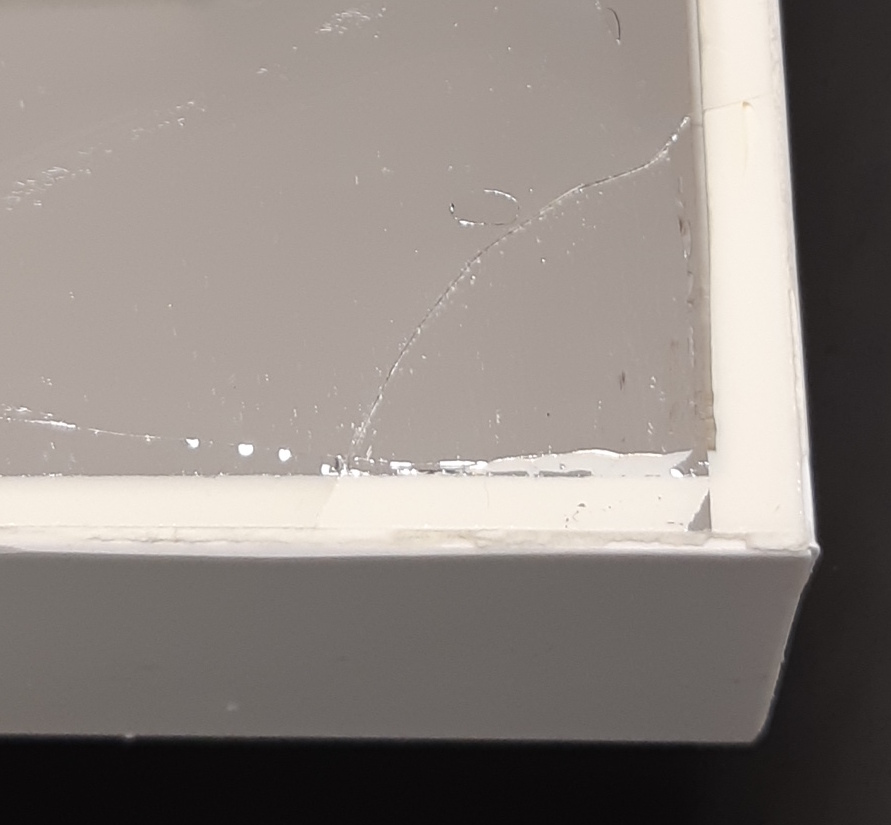
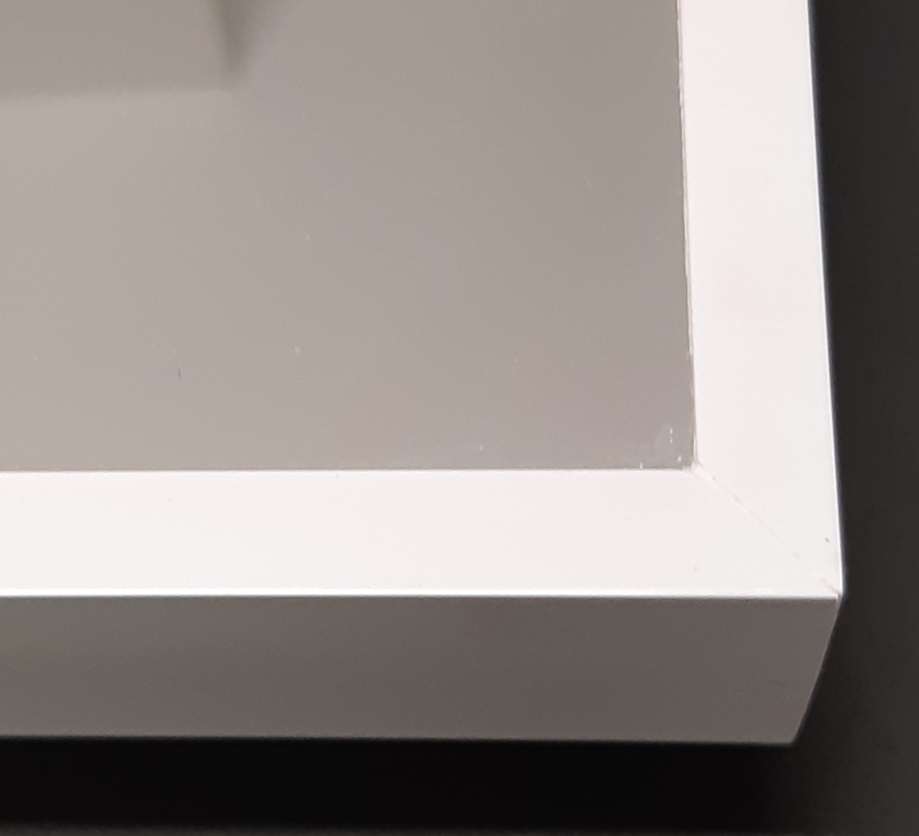
This is achieved by adapting the production process of cold-slumping glass mirrors [5, 6]. One side of a 0.4 mm thin glass sheet is covered with aluminum and glued to the sandwich structure, the uncoated side facing up. A lot of care has been taken to not damage the thin glass sheet in the gluing process, especially at the edges of the sheet. The thin glass sheet is slightly larger than the glass of the backing structure, the side of the sandwich is covered with a thick layer of silicone and a plastic frame. For the first prototype mirrors, this resulted in some small cracks in the thin glass sheet. The addition of a short, L-shaped plastic border protecting the edge of the thin glass sheet eliminated this problem, see Fig. 1. In May 2019, a larger production of these mirror types was started. As of that date, several prototypes were produced and evaluated, the results of these measurements are presented in the following section. Each mirror weighs 18 kg, about half compared to some of the first MAGIC mirrors that are still being used (30–40 kg), and similar compared to more recent mirrors (12–20 kg).
4 Measurements of Reflectivity and Point Spread Function
4.1 Laboratory
Two 1 m2-sized prototypes according to the MAGIC standards were produced (IDs 223 and 224). In the following months, four more (IDs 225–228) were produced with smoother surface, and finally one mirror (ID 229) was produced with improved edge protection, see closeup in Fig. 1.
The evaluation of the reflectivity of the mirrors of these mirrors was performed at the Max-Planck-Institute for Physics (MPP) in Munich [7], the focusing properties were checked at DESY Zeuthen at a test stand currently evaluating mirrors for the Middle Size Telescopes (MST) of CTA [8]. Before the mirror is released by MLT, several measurements are done at the manufacturing site, which are used to cross check the results obtained in the laboratories.
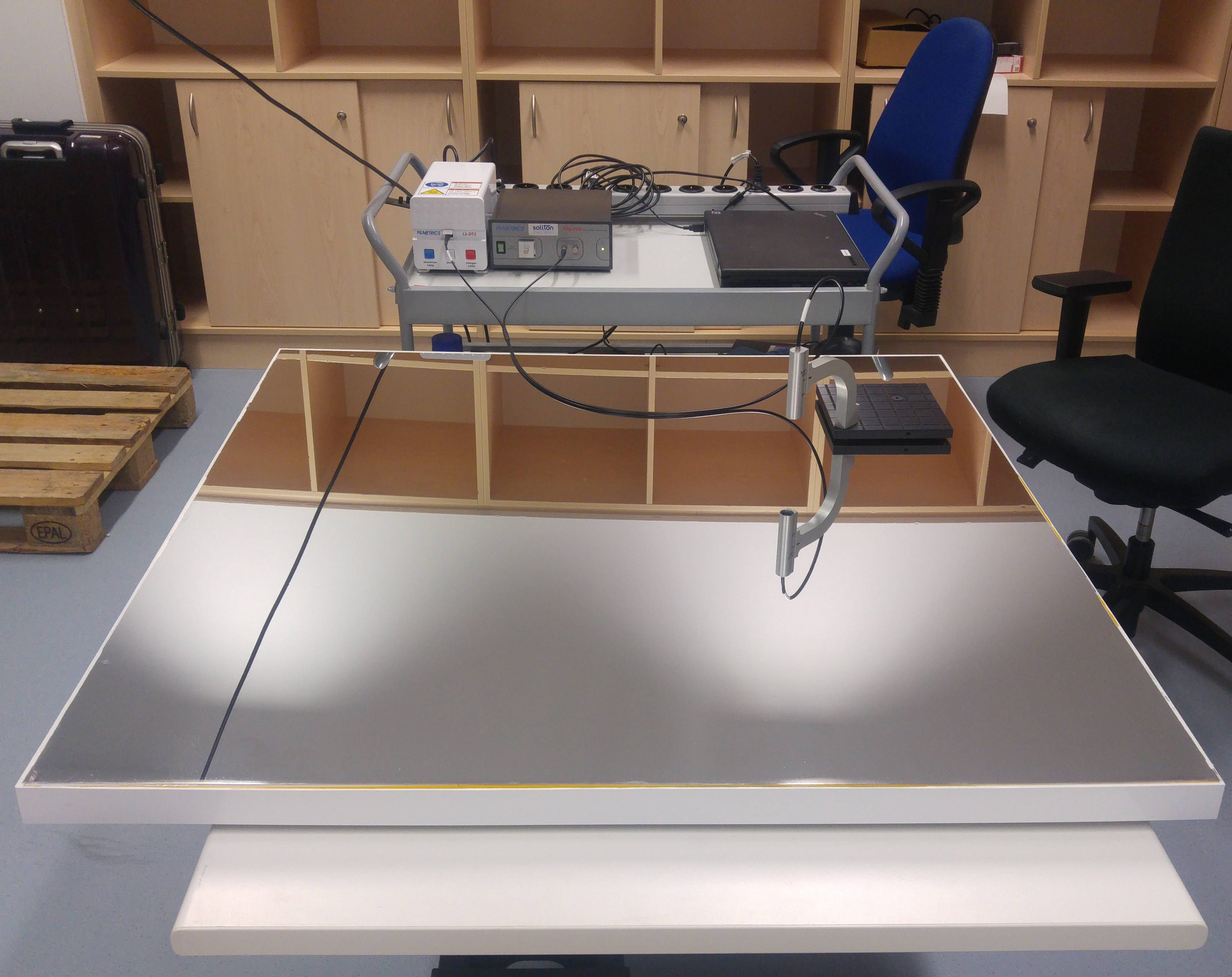
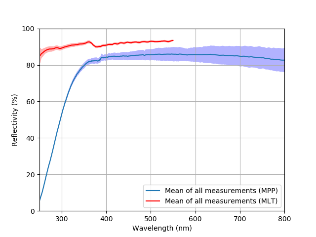
At MPP, a non-contact device for measuring the thicknesses of a thin film and its reflectivity was used to perform reflectivity measurements. It consists of a deuterium-halogen light-source with glass fiber output, which would illuminate from a short distance the sample under test. The light reflected from the sample is collected by the fiber and analyzed with a spectrograph. For the measurement, the 1 m2-sized samples were placed on a table and the sampling stage of the device was rotated to allow placing the light output directly over the mirror, see Fig. 1 for an image of the setup. The averages of those measurements of the mirrors are shown in Fig. 2. Also shown are the reflectivity measurements done by MLT using an almost identical non-contact device. The measurements are done directly on the reflective aluminum surface, which explains the much higher reflectivity in the UV range. Below 350 nm, the reflectivity is reduced due to the transmission properties of the selected ultra-thin glass sheet.
The setup at DESY used to measure the focal length and point spread function (PSF) of the mirrors consists of a metal structure on which the mirror is fixed, and a dark box containing the light source and electronics to measure the reflected light. The mirror is placed at roughly twice its focal length with respect to the dark box, this method to measure the PSF is called 2f setup. Inside the dark box, an LED light source is installed on a movable carriage. A collimator in front of the LED guides the outgoing light towards an exit hole in the box through which it illuminates the mirror. Through another hole, the reflected light enters and hits a reflective screen inside the dark box. Facing the screen, a CCD camera is installed to take pictures of the reflected spot.
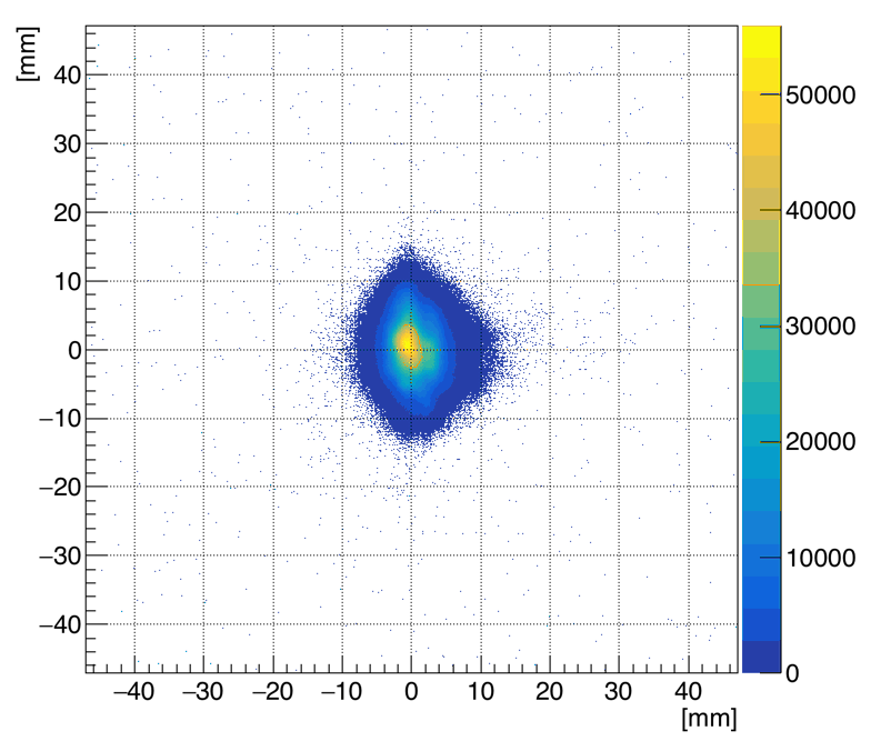
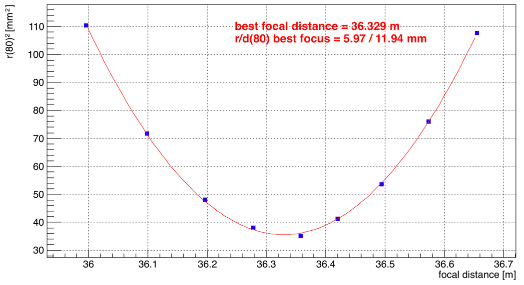
The focal length and the spot size at the focus of a mirror are both determined in a single measurement procedure. Several pictures of the spot are taken, scanning the distance along the focal length by moving the carriage with light source and camera inside the dark box. For each of these pictures, the PSF diameter (radius ) of the circle which contains 80% of the reflected light is determined, see left panel of Fig. 3. The right panel of Fig. 3 shows , which is proportional to the area covered by the light spot, as a function of the distance from the mirror. The data points are fitted with a parabola, whose minimum yields the focal point and the PSF value of at the best focus. The measurement at MLT is also done in a 2f setup, the light source and camera are moved on a sled to change the distance to the mirror. Several images are taken at varying distance to determine the best focus and at that point. The determination of best focus is only done by hand with an accuracy of about 50 mm, no fit is performed. In addition, the surface roughness and radius of the mirror are determined with a 3D scanner.
To see whether the focusing properties of the mirrors are constant after strong temperature fluctuations, two mirrors (IDs 223 and 224) were put into a climate chamber at DESY and underwent about five temperature cycles from C to C during three days. After this, the measurements of PSF and reflectivity were repeated. The results before and after the exposure to temperature changes were consistent within the systematic uncertainties of the measurement setup. The actual performance at extreme temperatures still needs to be studied.
| Radius | Best focus | PSF (mm) | Reflectivity (%) | ||||||||
| ID | (mm) | (mm) | at best focus | at 320 nm | at 350 nm | at 400 nm | |||||
| MLT | MLT | DESY | MLT | DESY | MLT | MPP | MLT | MPP | MLT | MPP | |
| 223 | 36614 | 36600 | 36572 | 16.47 | 15.63 | – | 67.3 | – | 78.1 | – | 84.1 |
| 224 | 35873 | 36500 | 36511 | 14.43 | 11.27 | – | 67.8 | – | 79.0 | – | 83.8 |
| 225 | 35839 | 36100 | 36197 | 16.50 | 14.28 | 91.8 | 67.9 | 92.7 | 79.9 | 91.6 | 84.0 |
| 226 | 35934 | 36300 | 36400 | 16.99 | 11.36 | 91.1 | 68.3 | 92.0 | 79.2 | 90.8 | 84.1 |
| 227 | 36004 | 36300 | 36329 | 14.95 | 11.94 | 90.0 | 68.4 | 91.2 | 80.3 | 90.3 | 84.6 |
| 228 | 36013 | 36800 | 36742 | 12.70 | 12.70 | 89.2 | 69.2 | 90.4 | 80.7 | 89.8 | 85.3 |
| 229 | 35983 | 36650 | – | 13.40 | – | 91.7 | – | 92.6 | – | 91.7 | – |
In Tab. 1, the measurements done at MPP, DESY and MLT are summarized. For mirrors 223 and 224, no measurements from the manufacturing site at MLT are available, mirror 229 has not been measured at MPP or DESY. The results of the best focus measurements from DESY and MLT agree within 100 mm, which is explained by the rough distance scan at MLT. The 3D measurements of the radius show larger differences to the best focus values, almost 800 mm for mirror 228, and systematically smaller radii. The 3D measurements are done with the mirror lying flat on a table, while for the 2f setup the mirror is hanging vertically. The mirror is deforming and the measured radius is different. The surface roughness determined by the 3D measurement is between 4 and 12 µm (RMS) with peak-to-valley values between 20 and 85 µm.
4.2 In situ
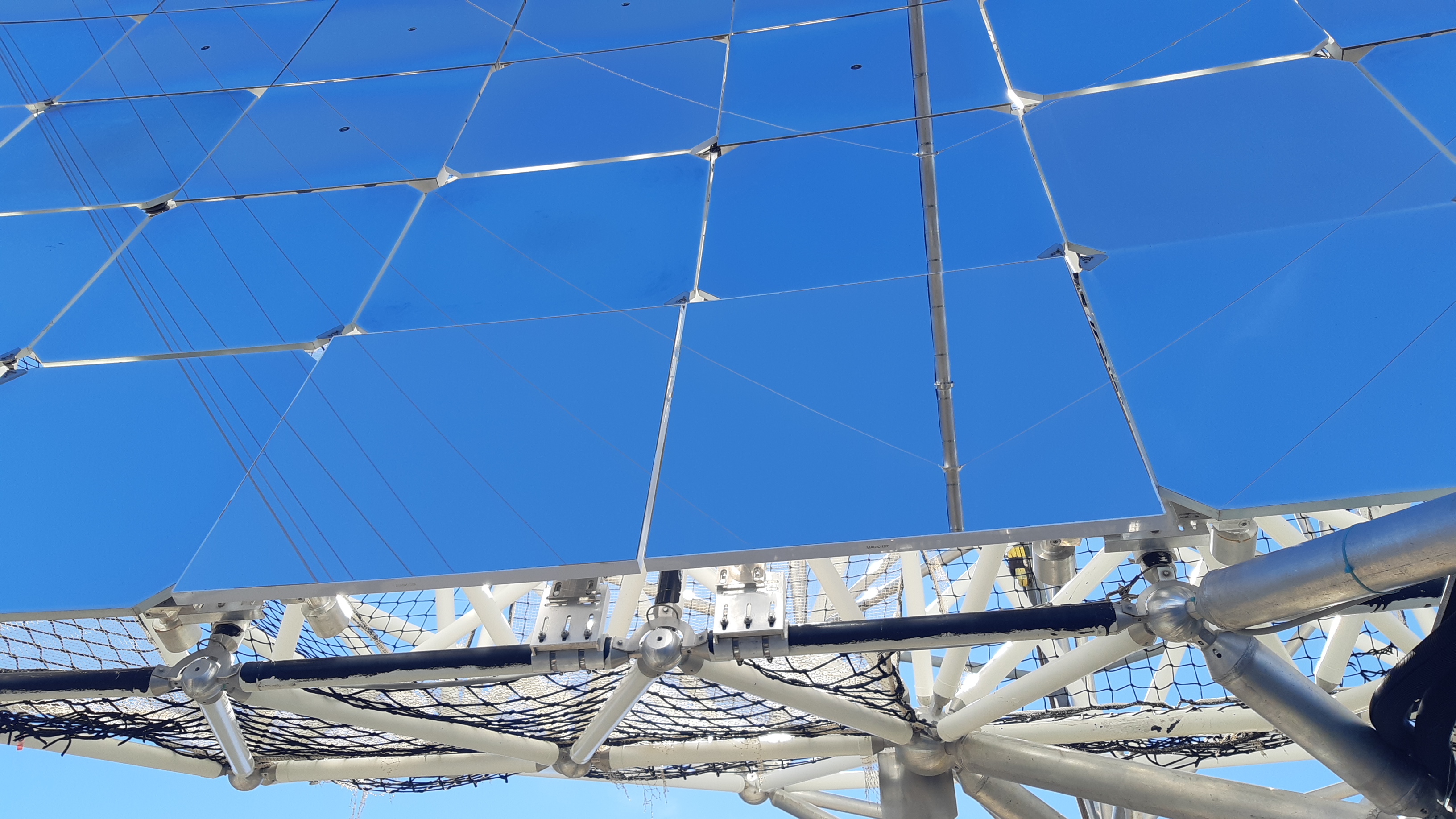
In October 2018, prototype mirrors 227 and 228 were installed in the MAGIC-II reflector. They have a curvature radius around 36 m, which is the maximum radius of the mirrors on the outside of the dish, the two mirrors were installed at the bottom edge, see Fig. 4. This has the additional benefit of making visual inspection easier when the telescope is parked. In the 9 months since the installation, no change in the surface or the edges was observed.
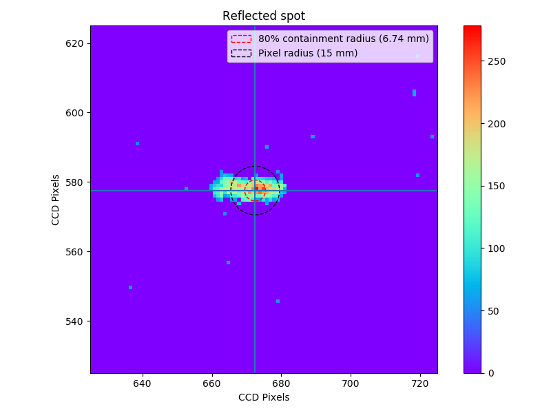
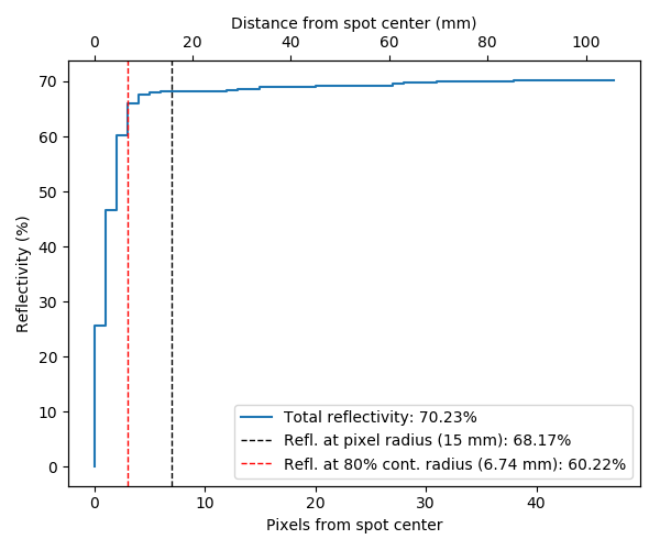
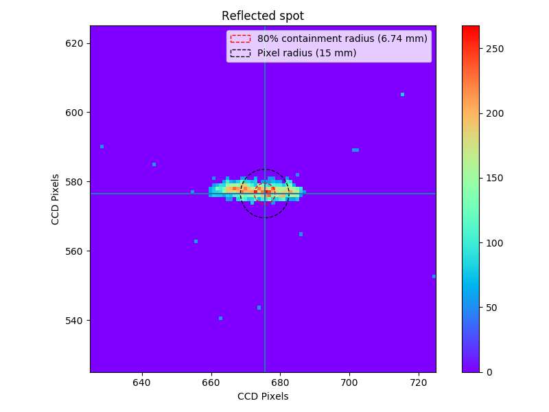
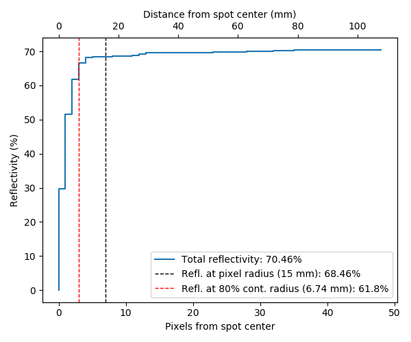
The PSF and reflectivity of the mirrors is checked periodically by tracking a bright star, focusing the reflected light on a square target in front of the PMT camera, focused at infinity. An image is taken using a CCD camera mounted in the dish center, containing the direct light from the star and the reflected light on the target [4]. The of the PSF is found by integrating the light of the reflected spot and determining the 80% containment. The reflectivity is determined by dividing the integrated light of the reflected spot by that of the direct star light, applying corrections for the reflectivity of the target, mirror area, opening angle of the CCD camera and other geometrical factors. While the total reflectivity of the mirror is an important parameter, the reflectivity within is an indicator of the focused reflectivity. The light reflected far from the central spot does not contribute in the central pixel and is a source of background in other pixels of the camera.
In Fig. 6 and 6 the results are shown for the two prototypes. The reflected spot is very elongated, this aberration is a result of the placement of the mirrors at the edge of the reflective surface. The mirrors are spherical but the ideal shape of the reflector is parabolic, at large distances to the center the difference in curvature between the mirror and the ideal shape is different along the axes of the mirror and the spot is distorted in one direction. To correct for this, the 80% containment radius was evaluated along the projection of the reflected light along the axis that is not distorted. The values of 13.5 mm for both mirrors, the focused reflectivity of 60.2% and 61.8%, and the total reflectivity of 71.5% and 69.5% are very good.
5 Outlook
In conclusion, the novel back-coated mirror samples show excellent focusing properties, high reflectivity, and they are stable under short-term temperature variations. These mirrors are expected to have a lifetime of a few decades, on the order of the lifetime of a telescope, and are much easier to maintain than the mirrors that are currently being used in Cherenkov telescopes. Two of these back-coated mirror panels were installed on MAGIC in October 2018 to test their longterm stability, and 29 more will be installed in 2019 to replace part of the 10–15 year old original mirrors that show strong signs of degradation. This will allow to evaluate the performance of a significant sample of these novel mirrors, which will provide an important input for the CTA collaboration.
Acknowledgements
References
- [1] Doro et al., Nucl. Inst. Meth. A 595 (2008) 200–203.
- [2] Roache et al., Proc. of 29th ICRC, Pune, 1397–1400, 2008.
- [3] Förster et al., Proc. of 32nd ICRC, Beijing, 133, 2011.
- [4] Mirzoyan et al., Astropart. Phys. 105 (2018) 1–12.
- [5] Pareschi et al., Adv. Opt. and Mech. Tech. in Tel. and Instr. 7018 (2008) 70180W.
- [6] Canestrari et al., Optical Engineering 52 (2013) 051204.
- [7] J. van Scherpenberg, Master’s Thesis, TU München, 2018.
- [8] J. Balkenkohl, Bachelor’s Thesis, Humboldt University Berlin, 2017.