AR-based interaction for safe human-robot collaborative manufacturing
Abstract
Industrial standards define safety requirements for Human-Robot Collaboration (HRC) in industrial manufacturing. The standards particularly require real-time monitoring and securing of the minimum protective distance between a robot and an operator. In this work, we propose a depth-sensor based model for workspace monitoring and an interactive Augmented Reality (AR) User Interface (UI) for safe HRC. The AR UI is implemented on two different hardware: a projector-mirror setup and a wearable AR gear (HoloLens). We experiment the workspace model and UIs for a realistic diesel motor assembly task. The AR-based interactive UIs provide 21-24% and 57-64% reduction in the task completion and robot idle time, respectively, as compared to a baseline without interaction and workspace sharing. However, subjective evaluations reveal that HoloLens based AR is not yet suitable for industrial manufacturing while the projector-mirror setup shows clear improvements in safety and work ergonomics.
I INTRODUCTION
Industrial manufacturing is going through a process of change toward flexible and intelligent manufacturing, the so-called Industry 4.0. Human-robot collaboration (HRC) will have a more prevalent role and this evolution means breaking with the established safety procedures as the separation of workspaces between robot and human operator is removed. However, this will require special care for human safety as the existing industrial standards and practices are based on the principle that operator and robot workspaces are separated and violations between them are monitored.
The International Organization for Standardization (ISO) Technical Specification (TS) 15066 [1] has recently addresses this need for safety with industrial collaborative robotics and defines four different collaborative scenarios. The first specifies the need and required performance for a safety-rated, monitored stop (robot moving is prevented without an emergency stop conforming to the standard). The second outlines the behaviors expected for hand-guiding a robot’s motions via an analog button cell attached to the robot. The third specifies the minimum protective distance between a robot and an operator in the collaborative workspace, below which a safety-rated, controlled stop is issued. The fourth limits the momentum of a robot such that contact with an operator will not result pain or injury. Our work focuses on the third scenario where the operator-robot distance is communicated interactively.
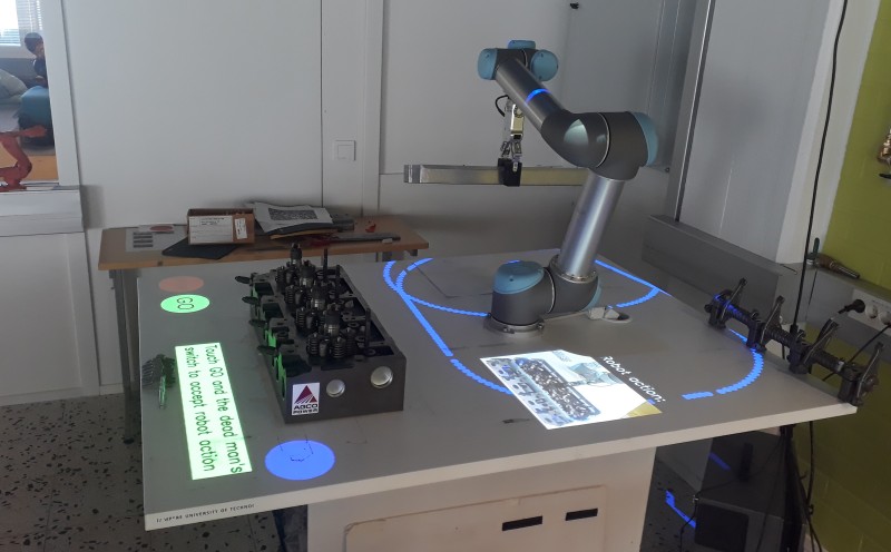
Marvel and Norcross [2] propose methods for the ISO/TS 15066 defined human-robot speed and separation monitoring based on measurable quantities (robot and operator speeds and uncertainties). The main focus of this work is to define a model to monitor safety margins with a depth sensor and to communicate the margins to the operator with an interactive User Interface (UI) (Figure 1).
We propose a shared workspace model for HRC manufacturing and interactive UIs. The model is based on the virtual zones introduced by Bdiwi et al. [3]: robot zone and human zone. In the human zone an operator can freely move and the robot is not allowed to enter. The robot zone is dynamically changing based on robot tasks and if the operator or any other object enters the robot zone, the robot is halted. In the proposed model, the two zones are separated by a safety monitored danger zone and any changes in the workspace model, either from the robot or operator side, cause halting the robot. The purpose of the safety zone is to allow dynamic update of the workspace model without compromising safety.
II RELATED WORK
Human-Robot Collaboration (HRC) in industrial manufacturing
Manufacturing industry leans on industrial standards that define safety requirements for Human-Robot Collaboration and therefore it is important to reflect research to the existing standards. Hitherto the main safety principle has been separation of human and robot workspaces and monitoring their violations. However, Industry 4.0 requires more flexible HRC and therefore the recent ISO/TS 15066 [1] provides best practices for shared workspaces. Marvel and Norcross [2] proposed methods for the ISO/TS 15066 compliant human-robot speed and separation monitoring. However, shared workspaces are yet only rarely used in industry as shown in a recent survey [4].
There have been attempts to formalize HRC in industrial settings such as Bdiwi et al. [3] who introduce four levels of HRC. The proposed workspace model, safety monitoring and User Interfaces (UIs) in our work are consistent with their collaboration levels Level 1 and Level 2. In Level 1 the robot and operator work close to each other, but have their own tasks. In Level 2 there is an additional cooperation zone where the robot and operator collaborate without physical interaction, for example, the robot holds a component firmly and stationary. Level 3 defines a handing-over zone and Level 4 adds interaction where, for example, human guides a heavy component held by the robot. From the safety perspective, Lasota et al. [5] provide a survey of existing HRC safety approaches and divide them into four categories: Safety Through Control, Safety Through Motion Planning, Safety Through Prediction and Safety Through Consideration of Psychological Factors. Our works belongs to the Safety Through Control category.
Safety through control is the most active research field in HRC safety. There are existing works to stop a robot for collision avoidance [6, 7, 8] and motion re-planning [9, 10]. The proposed workspace model and safety monitoring are inspired by the safety zones in [3] and instead of a passive system we propose AR-based interaction for HRC.
Augmented Reality in HRC
Shared workspace HRC requires seamless and safe interaction between a robot and an operator. These have been studied in several recent works that augment the workspace with interactive and dynamic user interface features [11, 12, 8].
Chadalavada et. al [11] proposed a projector based safety system for mobile robots operating on a flat industrial floor. The planned navigation path was projected on the floor to increase human awareness. Their user study verified that the projector system increased predictability and transparency experience of co-workers in the same space with the robots.
Andersen et al. [12] proposed a projector based display for HRC in industrial car door assembly. User studies of the systems against two baselines, a monitor display and simple text descriptions, showed clear improvements in the terms of effectiveness and user satisfaction.
Vogel et al. [13, 14, 8] have proposed multiple projector-camera based systems for safe HRC in a similar setting to ours. [13] introduces a safety monitoring system based on a projector and multiple camera based monitoring. The robot working area is projected by a standard DLP projector and the violations are detected by geometric distortions of the projected line due to depth changes. In the more recent work [8] the system is installed to an industrial workcell with a shared screwing task. Our model is based on a depth camera which make workspace model update and monitoring more straightforward.
Wearable AR gear, also referred to as “Augmented Reality Head-mounted Displays”, have recently gained momentum. Huy et al. [15] use a head-mounted display in an outdoor application where a projector system cannot be used. Elsdon et al. [16] introduced a handheld spray robot where the control of the spraying was shared between the human and robot. However, it is unclear how mature the wearable AR gear technology is for real industrial manufacturing and therefore we compara wearable AR and projector-based AR in our work.
The main contributions of our work are:
-
•
We propose a depth-based model for shared workspace Human Robot Collaboration. The model is based on three zones, human, robot and danger, and their continuous update and safety monitoring.
-
•
We propose two AR-based and interactive User Interfaces (UIs) based on the proposed model: projector-mirror and wearable AR gear (HoloLens).
We experimentally evaluate the model and UIs on a realistic industrial assembly task and report results from quantitative and qualitative (subjective) evaluations with respect to performance, safety and ergonomy, and against a non-shared workspace baseline.
III The shared workspace model
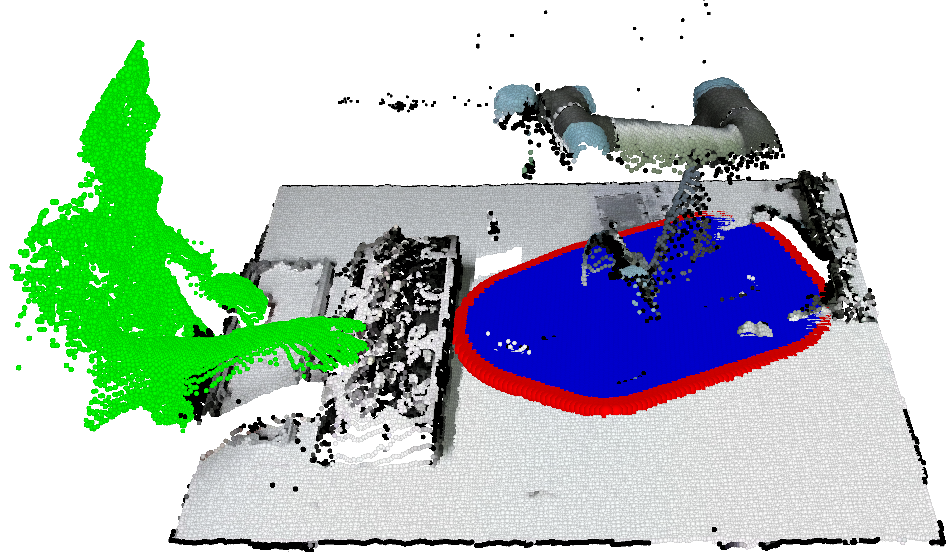
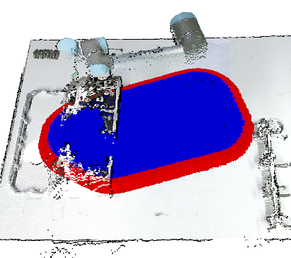
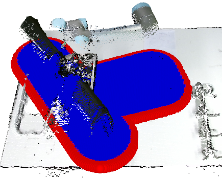
In our model, a shared workspace is modelled with a single depth map image and divided to three virtual zones: robot zone , human zone and danger zone (Figure 2). The zones are modelled by binary masks in the same space as which makes their update, display and monitoring fast and simple.
III-A Depth-based workspace model
We consider a shared workspace monitored by a depth sensor which can be modelled as a pin-hole camera parametrized by two matrices: the intrinsic camera matrix , modelling the projection of a Cartesian point to a image plane, and the extrinsic camera matrix , describing the pose of the camera in the world. The matrices can be solved by the chessboard calibration procedure [17]. For simplicity we use the robot coordinate frame as the world frame.
After calibration the points in the depth sensor plane can be transformed to a Cartesian point in world frame and finally to the workspace model of the size :
| (1) |
| (2) |
where is the inverse coordinate transformation and is the projective transformation. Now, computations are done efficiently in and (1) is used to display the results to the AR hardware and (2) to map the robot control points (Sec. III-B) to the workspace model.
III-B Binary zone masks
Since all computation is done in the depth image space the three virtual zones can be defined as binary masks of the size : the robot zone , the danger zone and the human zone .
The robot zone mask
The zone is initialized using set of control points containing minimum number of 3D points covering all the extreme parts of the robot. The point locations in the robot frame are calculated online using a modified version of the Hawkinses model [18] and projected to . Finally, the projected points are converted to regions having radius of and a convex hull [19] enclosing all the regions is computed and the resulting hull is rendered as a binary mask representing .
The danger zone mask
Contour of the and constructed by adding a danger margin to the robot zone mask and then subtracting from the results:
| (3) |
The human zone mask
This is easy to compute as a binary operation since the human zone is all pixels not occupied by the robot zone or the danger zone :
| (4) |
III-C Adding the manipulated object to and
An important extension of our model is that the known objects that the robot manipulates are added to the robot zone and (see Figure 2). This guarantees that the robot does not accidentally hit the operator with an object it is carrying. In such case a new set of control points is created using known dimensions of the object and point locations of the robot joints. Finally the binary mask for the object is created similarly as and the final shape of the zones are computed by fast binary operations:
| (5) |
| (6) |
III-D Safety monitoring
The main safety principle is that the depth values in the danger region must match with the stored depth model. Any change must produce immediate halt of the system. Our depth based model in the robot frame provides now fast computation since the change detection is computed as a fast subtraction operation
| (7) |
where is the most recent depth data transferred to same space as our workspace model. The difference bins (pixels) are further processed by Euclidean clustering [20] to remove spurious bins due to noisy sensor measurements.
Finally, the safety operation depends on which zone a change is detected:
| (8) |
where is the depth threshold.
In the first case, the change has occurred in the danger zone and therefore the robot must be immediately halted to avoid collision. For maximum safety this processing stage must be executed first and must test all pixels before the next stages.
In the second case, the change has occurred in the robot working zone and is therefore caused by the robot itself by moving and/or manipulating objects and therefore the workspace model can be safely updated.
In the last case, the change has occurred in the human safety zone and we create the mask that represents the changed bins (note that the mask is recreated for every measurement to allow temporal changes, but it does not affect robot operation). Robot can continue operation normally, but if its danger zone intersects with any 1-bin in , then these locations must be verified from the human co-worker via user interface. If the bins are verified, then these values are updated to the workspace model and operation continues normally. Note that our system does not verify each bin separately, but a spatially connected region of changed bins. This operation allows a shared workspace and arbitrary changes in the workspace which do occur away from the danger zone.
IV The user interfaces
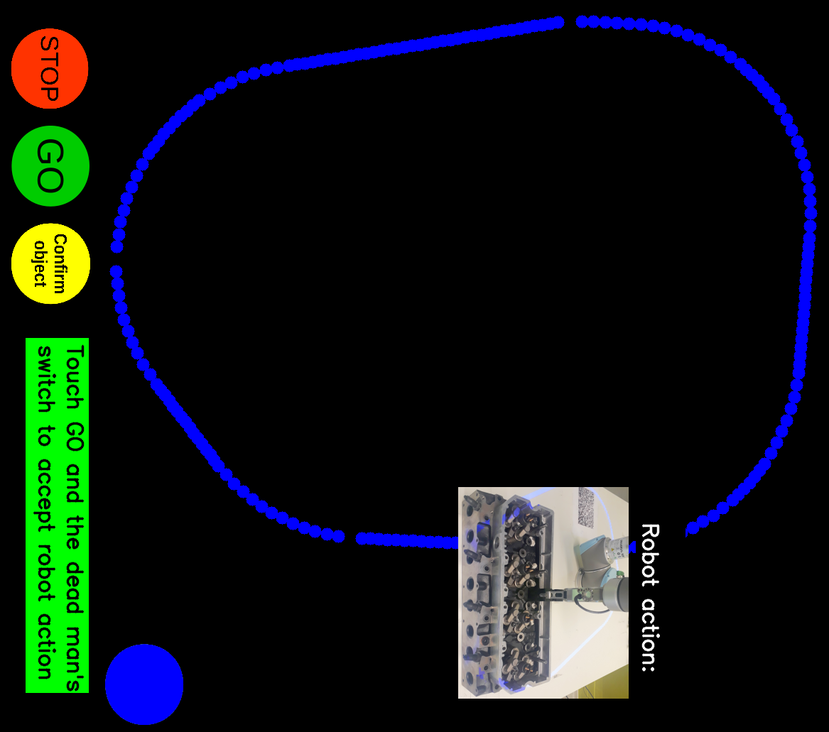
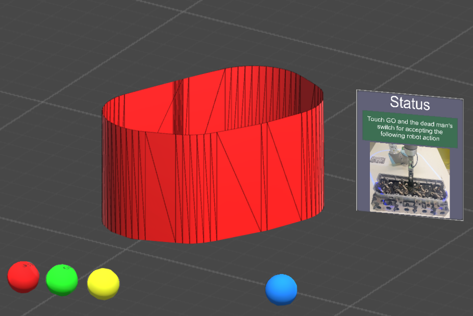
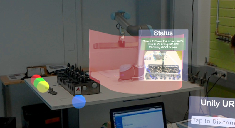
The danger zone defined in Section III-B and various User Interface (UI) components are rendered to graphical objects in two AR setups (Figure 3).
IV-A UI Components
The proposed UI contains the following interaction components (Figure 3 and Figure 2): 1) a danger zone that shows the region operators should avoid; 2) highlighting changed regions in the human zone; 3) “GO” and “STOP’ buttons to start and stop the robot; 4) “CONFIRM” button to verify and add changed regions to the current model; 5) “ENABLE” button that needs to be pressed simultaneously with the “GO” and “CONFIRM” buttons to take effect; and 6) a graphical display box (image and text) to show the robot status and instructions to the operator.
The above UI components were implemented to two different hardware, projector-mirror and HoloLens. The UI components and layout were the same for the both hardware to be able to compare the human experience on two different types of hardware.
IV-B Projector-mirror AR
The projector-mirror setup is adopted from Vogel et al. [13, 14, 8] with the main difference that we replace multiple RGB cameras with a single RGB sensor (KinectV2). A standard 3LCD projector is installed to the ceiling to point to a tilted mirror that reprojects the picture to the workspace area. The mirror is needed to expand the projection area of the standard projector, but could be replaced with a wide angle lens projector. The projector outputs a color image with 50Hz frame rate. The projector coordinate frame is calibrated to the world (robot) coordinate frame using the inverse camera calibration with a checkerboard pattern [21].
IV-C Wearable AR (HoloLens)
As a state-of-the-art head-mounted AR display, we adopt Microsoft HoloLens. The headset can operate without any external cables and the 3D reconstruction of the environment as well as accurate 6-DoF localization of the head pose is provided by the system utilizing an internal IMU sensor, four spatial-mapping cameras, and a depth camera. The data exchange between HoloLens and our model is done using wireless TCP/IP. We implemented a Linux server that synchronizes data from the robot simulator (ROS) to HoloLens and back.
The interaction buttons are displayed as semi-transparent spheres that are positioned similar to the projector-mirror UI (Figure 1). In addition, we render the safety region as a solid virtual fence. The fence is rendered as a polygonal mesh having semi-transparent red texture. From the 2D boundary and a fixed fence height we construct the fence mesh from rectangular quadrilaterals that are further divided to two triangles for the HoloLens rendering software.
The UI component and the virtual fence coordinates are defined in the robot frame and transformed to the HoloLens frame by
| (9) |
where is a known static transformation between the robot and an AR marker (set manually to the workspace) and is the transformation between the marker and the user holographic frame . Once the pose has been initialized the marker can be removed and during run time is updated by HoloLens software.
V Engine assembly task
Our task is adopted from a local diesel engine manufacturing company and we also present a baseline without a shared workspace.
V-A Task description
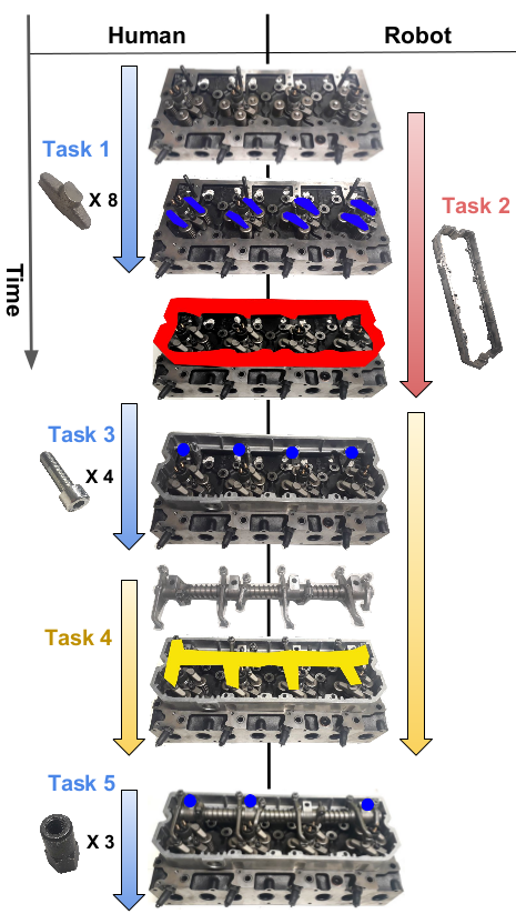
The task used in our experiments is a part of a real engine assembly task from a local company. The task is particularly interesting as one of the sub-tasks is to insert a rocker shaft that weights 4.3 kg and would therefore benefit from human-robot collaboration. The task is illustrated in Figure 4 which also shows the five sub-tasks (H denotes the human operator and R the robot): Task 1) Install 8 rocker arms (H), Task 2) Install the motor frame (R), Task 3) Insert 4 frame screws (H), Task 4) Install the rocker shaft (R+H) and Task 5) Insert the nuts on the shaft (H).
Tasks 1-3 and 5 are dependent so that the previous sub-task must be completed before the next can begin. Task 4 is collaborative in the sense that the robot brings the saft and moves to a force mode allowing physical hand-guidance of the end-effector. In the force mode, the robot applies just enough force to overcome the gravitational force of the object while still allowing the human to guide the robot arm for accurate positioning.
V-B A non-collaborative baseline
Our baseline is based on the current practices in manufacturing - the human and robot cannot operate in the same workspace simultaneously. In our setting, the operator must stay 4 meters apart from the robot when the robot is moving and the operator is allowed to enter the workspace only when the robot is not moving. In this scenario the collaborative Task 4 is completely manual, the robot only brings the part.
Safety in the baseline is ensured by a dead man’s switch button which the operator needs to press all the time for the robot to be operational. The baseline does not contain any UI components, but in the user studies the subjects are provided with textual descriptions of all sub-tasks.
VI Experiments
We report quantitative and qualitative results for the assembly task and compare the three setups.
VI-A Settings
The experiments were conducted using the model 5 Universal Robot Arm (UR5) and OnRobot RG2 gripper. KinectV2 was used as the depth sensor installed to the ceiling and capturing the whole workspace area. The AR displays, the projector or HoloLens, were connected to a single laptop with Ubuntu 16.04 OS and it performed all computations.
User studies
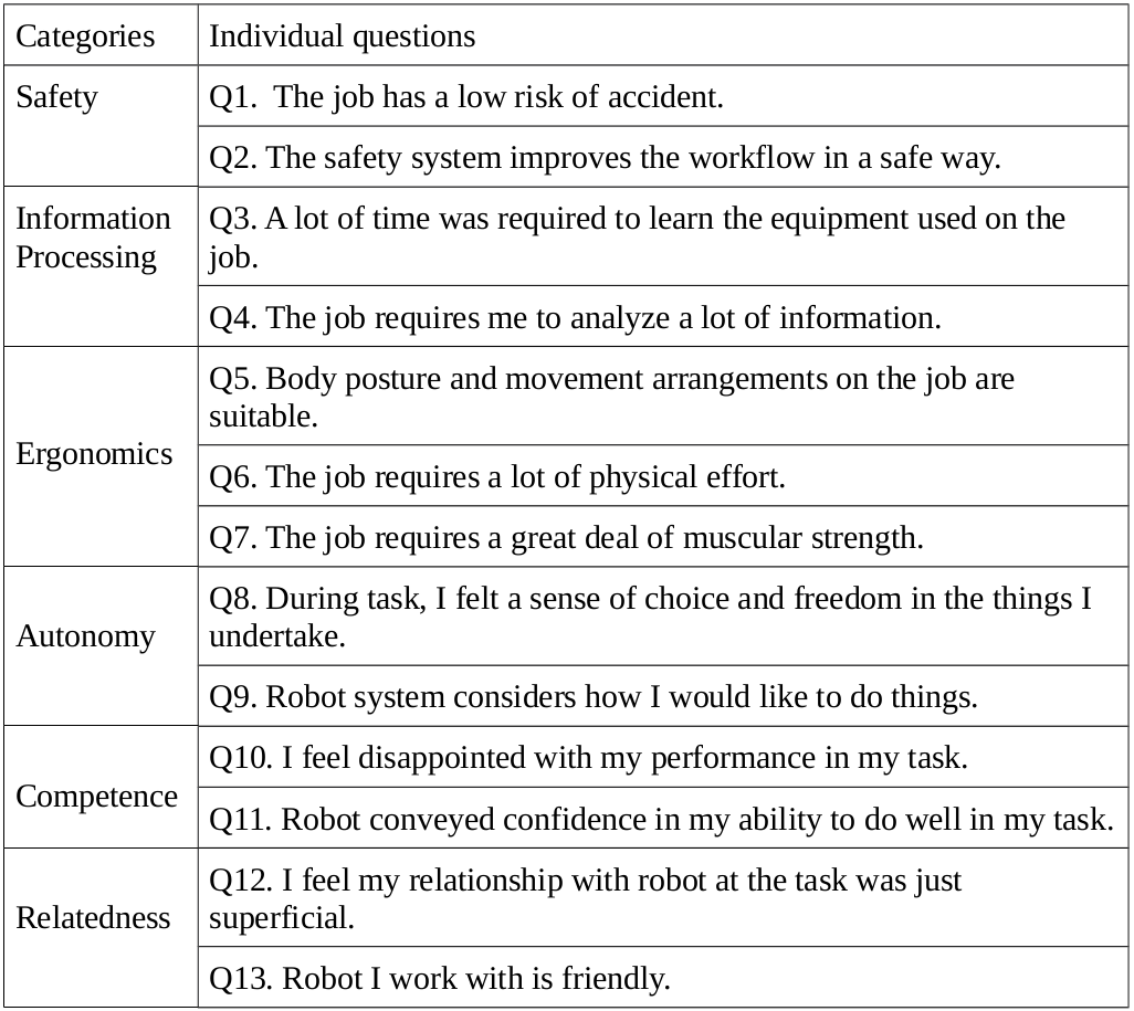
The experiments were conducted with 20 unexperienced volunteered university students. Their performance times were recorded and after experimenting the three systems they were asked the questionnaire in Figure 5. The goal of the questionnaire was to evaluate physical and mental stress aspects of the human co-workers during the task. The questions were selected to cover safety, ergonomics and mental stress experience as defined in Salvendy et al. [22], and autonomy, competence, and relatedness in Deci et al. [23]. Users were asked to score each question using the scale from 1 (totally disagree) to 5 (totally agree).
VI-B Quantitative Performance
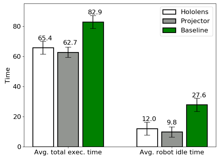
For quantitative performance evaluation we used two different metrics, Average total task execution time and Average total robot idle time, that measure the total performance improvement and the time robot is waiting for the operator to complete her tasks.
The results in Figure 6 show that the both AR-based interactive systems outperform the baseline where the robot was not moving in the same workspace with an operator. The difference can be explained by the robot idle time which is much less for AR-based interaction. The difference between the HoloLens and Projector based systems is marginal. On average, the AR-based systems were and faster than the baseline in the terms of the total execution time and the robot idle time respectively.
VI-C Subjective evaluation
Since the results from the previous quantitative evaluation of system performance were similar for the both HoloLens and Projector based AR interaction the user studies provided important information about the differences of the two systems.
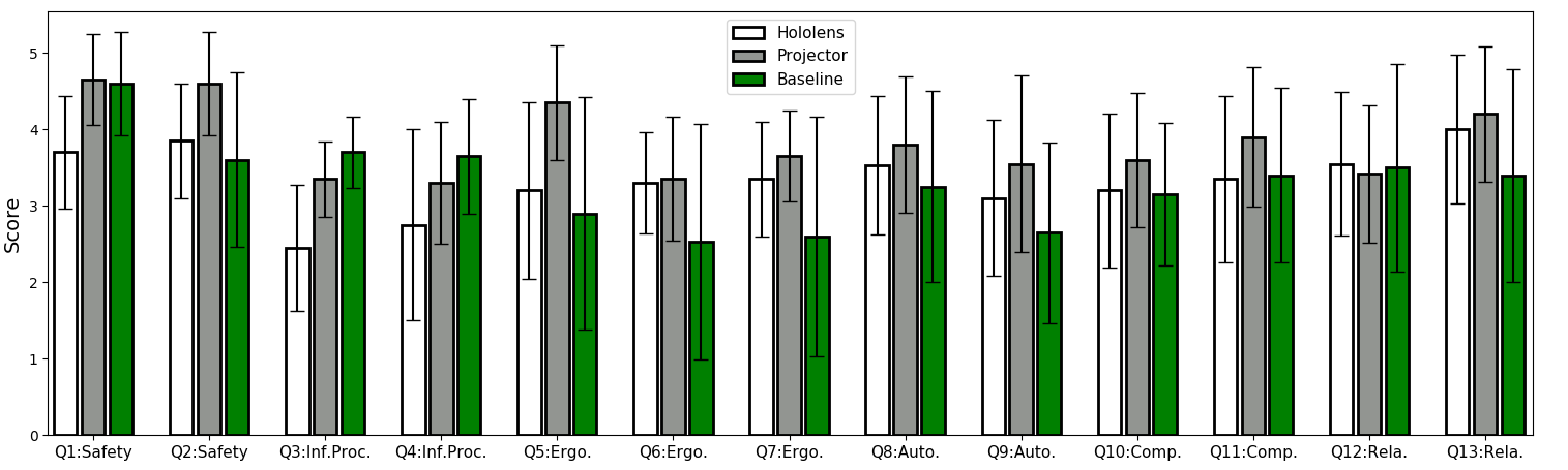
From the each 20 participant the 13 template questions (Q1-Q13) in Figure 5 were asked and the results analyzed. The average scores with the standard deviations are shown in Figure 7. The overall impression is that the Projector-based display outperforms the two others (HoloLens and Baseline), but surprisingly HoloLens is found inferior the baseline in many safety related questions.
The numerical values are given in Table I and these verify the overall findings. The projector-based method is considered the safest and the HoloLens-based method most unsafe with a clear margin. The amount of information needed to understand the task is smallest for the baseline while Projector-based has very similar numbers and again the HoloLens-based method was found clearly more difficult to understand. Ergonomy-wise the HoloLens and Projector based methods were superior likely to the fact that they provided help in installing the heavy rocker shaft. The autonomy numbers are similar for all methods, but the projector-based is found the easiest to work with. The users also found their performance best with the Projector-based system (Competence). The question Q12 was obviously difficult to understand for the users, but all users found the system with AR-interaction more plausible (Q13) than the baseline without interaction. Overall, the projector-based AR interaction in collaborative manufacturing was found safer and more ergonomic than the baseline without AR interaction and also the HoloLens-based AR.
| HoloLens | Projector | Baseline | ||
| Safety | Q1 | 3.7 | 4.7 | 4.6 |
| Q2 | 3.9 | 4.6 | 3.6 | |
| Information Processing | Q3 | 2.6 | 1.7 | 1.3 |
| Q4 | 2.3 | 1.7 | 1.4 | |
| Ergonomics | Q5 | 3.2 | 4.4 | 2.9 |
| Q6 | 1.7 | 1.7 | 2.5 | |
| Q7 | 1.7 | 1.4 | 2.4 | |
| Autonomy | Q8 | 3.5 | 3.8 | 3.3 |
| Q9 | 3.1 | 3.6 | 2.7 | |
| Competence | Q10 | 1.8 | 1.4 | 1.9 |
| Q11 | 3.4 | 3.9 | 3.4 | |
| Relatedness | Q12 | 3.6 | 3.4 | 3.5 |
| Q13 | 4.0 | 4.2 | 3.4 |
Below are free comments from the user studies that well point out the reasons why different systems were preferred or considered difficult to use:
-
•
HoloLens: “Too narrow field of view, head has to be rotated a lot.”
“Feels heavy and uncomfortable after a while.”
“Holograms feels to be closer than they actually are.” -
•
Projector: “I would choose the projector system over HoloLens”
“Easier and more comfortable to use” -
•
Baseline: “System could be fooled by placing object on the switch button.”
VII Conclusions
We proposed a computation model of the shared workspace in human-robot collaborative manufacturing. The model allows to monitor changes in the workspace to establish safety features. Moreover, we proposed a user interface for HRC in industrial manufacturing and implemented it on two different hardware for augmented reality, a project-mirror and wearable AR gear (HoloLens). In our experiments on a realistic assembly task adopted from automotive manufacturing the both AR-based systems were found superior in performance to the baseline without a shared workspace. However, the users found the projector-mirror system clearly more plausible for manufacturing work than the HoloLens setup.
References
- [1] International Organization for Standardization, ISO/TS 15066:2016 – Robots and Robotic Devices – Collaborative Robots, 2016.
- [2] J. Marvel and R. Norcross, “Implementing speed and separation monitoring in collaborative robot workcells,” Robotics and Computer-Integrated Manufacturing, vol. 44, 2017.
- [3] M. Bdiwi, M. Pfeifer, and A. Sterzing, “A new strategy for ensuring human safety during various levels of interaction with industrial robots,” CIRP Annals, vol. 66, no. 1, 2017.
- [4] V. Villani, F. Pini, F. Leali, and C. Secchi, “Survey on human–robot collaboration in industrial settings: Safety, intuitive interfaces and applications,” Mechatronics, 2018.
- [5] P. Lasota, T. Fong, and J. Shah, “A survey of methods for safe human-robot interaction,” Foundations and Trends in Robotics, vol. 5, no. 4, 2017.
- [6] P. A. Lasota, G. F. Rossano, and J. A. Shah, “Toward safe close-proximity human-robot interaction with standard industrial robots,” 2014.
- [7] F. Flacco, T. Kroeger, A. De Luca, and O. Khatib, “A depth space approach for evaluating distance to objects,” Journal of Intelligent & Robotic Systems, vol. 80, no. 1, pp. 7–22, 2015.
- [8] C. Vogel, C. Walter, and N. Elkmann, “Safeguarding and supporting future human-robot cooperative manufacturing processes by a projection-and camera-based technology,” Procedia Manufacturing, vol. 11, pp. 39–46, 2017.
- [9] G. Dumonteil, G. Manfredi, M. Devy, A. Confetti, and D. Sidobre, “Reactive planning on a collaborative robot for industrial applications,” in Proceedings of the 12th International Conference on Informatics in Control, Automation and Robotics - Volume 2: ICINCO,, pp. 450–457, INSTICC, SciTePress, 2015.
- [10] V. V. Unhelkar, P. A. Lasota, Q. Tyroller, R.-D. Buhai, L. Marceau, B. Deml, and J. A. Shah, “Human-aware robotic assistant for collaborative assembly: Integrating human motion prediction with planning in time,” IEEE Robotics and Automation Letters, vol. 3, no. 3, pp. 2394–2401, 2018.
- [11] R. T. Chadalavada, H. Andreasson, R. Krug, and A. J. Lilienthal, “That’s on my mind! robot to human intention communication through on-board projection on shared floor space,” in Mobile Robots (ECMR), 2015 European Conference on, pp. 1–6, IEEE, 2015.
- [12] R. S. Andersen, O. Madsen, T. B. Moeslund, and H. B. Amor, “Projecting robot intentions into human environments,” in Robot and Human Interactive Communication (RO-MAN), 2016 25th IEEE International Symposium on, pp. 294–301, IEEE, 2016.
- [13] C. Vogel, M. Poggendorf, C. Walter, and N. Elkmann, “Towards safe physical human-robot collaboration: A projection-based safety system,” in IEEE/RSJ International Conference on Intelligent Robots and Systems (IROS), pp. 3355–3360, IEEE, 2011.
- [14] C. Vogel, C. Walter, and N. Elkmann, “A projection-based sensor system for safe physical human-robot collaboration,” in IEEE/RSJ International Conference on Intelligent Robots and Systems (IROS), pp. 5359–5364, IEEE, 2013.
- [15] D. Q. Huy, I. Vietcheslav, and G. S. G. Lee, “See-through and spatial augmented reality - a novel framework for human-robot interaction,” in 2017 3rd International Conference on Control, Automation and Robotics (ICCAR), pp. 719–726, April 2017.
- [16] J. Elsdon and D. Y, “Augmented reality for feedback in a shared control spraying task,” in IEEE International Conference on Robotics and Automation (ICRA), 2018.
- [17] F. C. Park and B. J. Martin, “Robot sensor calibration: solving AX= XB on the Euclidean group,” IEEE Transactions on Robotics and Automation, vol. 10, no. 5, pp. 717–721, 1994.
- [18] K. P. Hawkins, “Analytic inverse kinematics for the universal robots ur-5/ur-10 arms,” tech. rep., Georgia Institute of Technology, 2013.
- [19] R. L. Graham and F. F. Yao, “Finding the convex hull of a simple polygon,” Journal of Algorithms, vol. 4, no. 4, pp. 324–331, 1983.
- [20] R. B. Rusu, “Semantic 3d object maps for everyday manipulation in human living environments,” KI-Künstliche Intelligenz, vol. 24, no. 4, pp. 345–348, 2010.
- [21] I. Martynov, J.-K. Kamarainen, and L. Lensu, “Projector calibration by ”inverse camera calibration”,” in Scandinavian Conference on Image Analysis (SCIA), 2011.
- [22] G. Salvendy, Handbook of human factors and ergonomics. John Wiley & Sons, 2012.
- [23] E. L. Deci, R. J. Vallerand, L. G. Pelletier, and R. M. Ryan, “Motivation and education: The self-determination perspective,” Educational psychologist, vol. 26, no. 3-4, pp. 325–346, 1991.