Real-time Deformation with Coupled Cages and Skeletons
Abstract.
Skeleton-based and cage-based deformation techniques represent the two most popular approaches to control real-time deformations of digital shapes and are, to a vast extent, complementary to one another. Despite their complementary roles, high-end modeling packages do not allow for seamless integration of such control structures, thus inducing a considerable burden on the user to maintain them synchronized. In this paper, we propose a framework that seamlessly combines rigging skeletons and deformation cages, granting artists with a real-time deformation system that operates using any smooth combination of the two approaches. By coupling the deformation spaces of cages and skeletons, we access a much larger space, containing poses that are impossible to obtain by acting solely on a skeleton or a cage. Our method is oblivious to the specific techniques used to perform skinning and cage-based deformation, securing it compatible with pre-existing tools. We demonstrate the usefulness of our hybrid approach on a variety of examples.
1. Introduction
Interactive shape deformation is a fundamental building block in 3D modeling and many other applications. The various techniques available in the literature rely on simplified control structures: the user interacts with them, and the changes smoothly transfer to the high resolution controlled object (the skin) through a set of weights, which establish a relation between each point of the model and the handles of the control structure (Jacobson et al., 2014). The two most widely used controllers for real-time deformation, namely skeletons and cages, support complementary tasks: skeleton-based techniques are adequate to control rigid parts and pose articulated bodies; conversely, cage-based methods are best for smooth volumetric deformations. Each control structure becomes unwieldy and overly complicated to use where the other excels, thus pushing practitioners to use them together on the same skin.
Numerous discussions on how to combine skeletons and cages can be found on specialized forums, blogs and other online resources. Despite this interest from the community of practitioners, the problem of keeping them in sync and finding consensus between the deformations they induce is still open. To this end, an important issue is that there exists a plethora of alternative skeleton and cage techniques, which are already implemented in almost any available deformation software. Therefore, to promote a seamless integration of hybrid deformation approaches into well established software packages, it becomes crucial to guarantee some sort of flexibility and back-compatibility.
The complexity in combining skeletons and cages comes from the fact that they achieve deformation in substantially different ways. Skeleton-based techniques perform deformations that are relative to a particular pose of the skin, often called the rest pose: the deformed skin is always a combination of its shape in the rest pose with the current position of the skeleton. Conversely, cage-based deformation follows an absolute approach: the current position of the control cage entirely determines the skin it envelopes, with no particular reference pose existing.
Previous attempts to combine skeletons and cages fall short, either because they are not general enough, or because they break back-compatibility. Blender (2018) allows to link a control cage to a skeleton and move the cage through it. The communication is only mono-directional: edits performed on the cage do not reflect on the skeleton, thus requiring complex manual edits to reposition the centers of rotation of each bone. Jacobson and colleagues (2011) combined skeleton, cage, and point handles into a unified deformation meta-structure, but impose the simultaneous definition of all the handles and relative weights, and do not keep the sync between them. Moreover, their system implements a customized pipeline, which is not compatible with standard techniques.
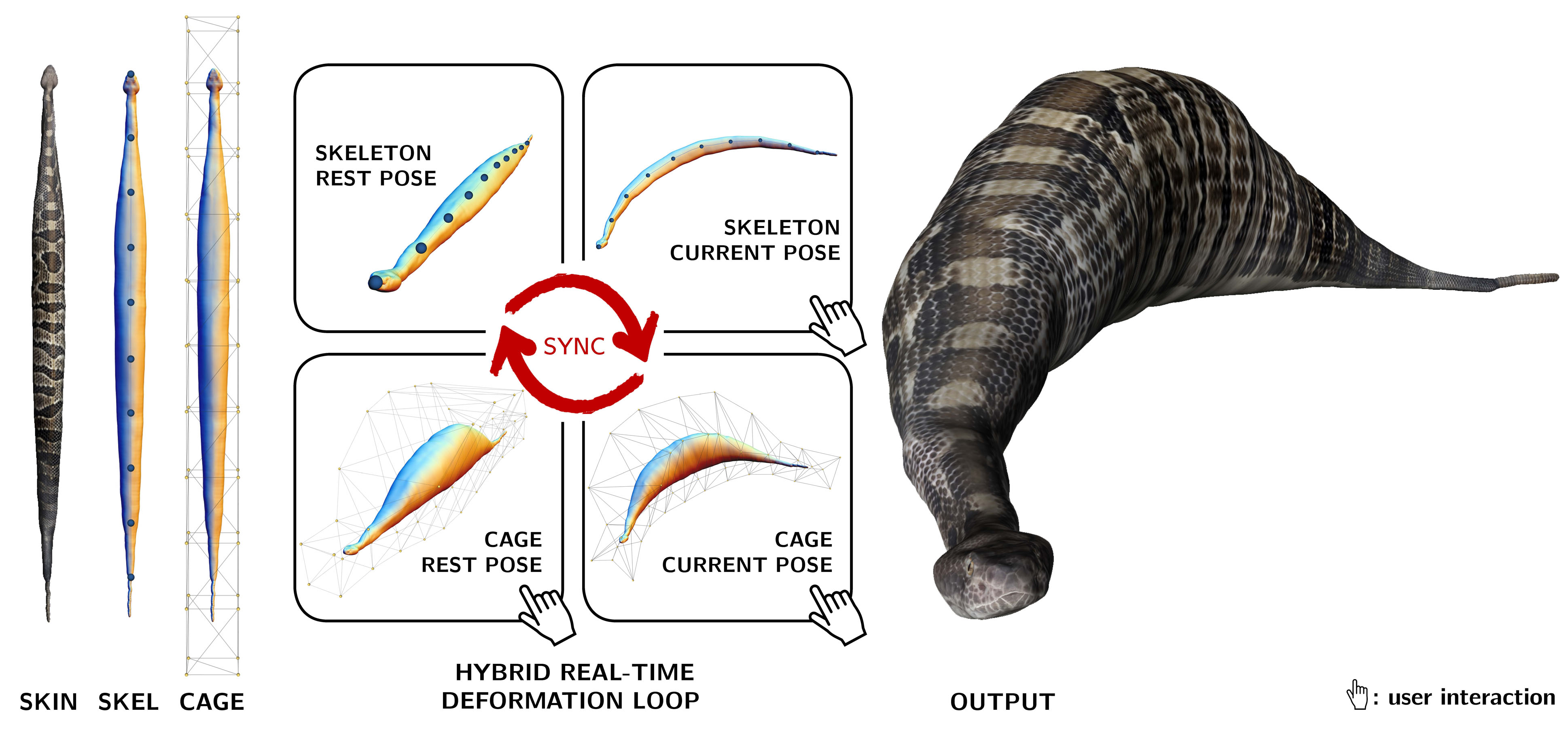
We propose a hybrid deformation paradigm that seamlessly combines skeletons and cages, providing a real-time framework where the user can operate using any interlaced combination of the two control structures. Our method is compatible with classical skeleton-based and cage-based deformation techniques: it just acts as middleware to reach consensus between the two control structures. In particular, skeleton deformations can be transferred to the skin using the popular LBS (Magnenat-Thalmann et al., 1989), DQS (Kavan et al., 2008), or any alternative approach (Figure 2). Linking weights can be either the result of an automatic computation (e.g. (Baran and Popović, 2007)) or hand painted by a digital artist, as it often happens in the industry. Similarly, cage-based deformation admits the use of any type of generalized barycentric coordinates that produce deformation through a linear relation between the cage handles and the vertices of the skin (Nieto and Susín, 2013). To achieve consensus between the two control structures we retain the relative nature of skeletons and extend it to the cages, which therefore exist both in the rest and the current pose (Figure 1). At modeling time the user guides a deformation by acting on one controller, and the system automatically updates all the other poses accordingly. Our approach makes it possible to edit shapes both in current and rest poses, and occurs in real-time, with negligible overhead to classical skeleton- and cage-based deformation workload. Figure 3 provides an overview of our framework, depicting the paths of user interactions.
Contribution.
Our main contribution is a deformation system that combines the deformation spaces of skeletons and cages, revealing a much larger deformation space which contains configurations that cannot be achieved using solely a skeleton or a cage. From a technical point of view, our contribution consists in a collection of synchronization operators that maintain the pose set up-to-date during the editing session in real-time. We demonstrate our hybrid deformation approach on a variety of examples, including shape modeling and digital animation (Section 5). Our software prototype already implements several skeleton and cage based techniques, and can potentially embrace most existing techniques based on these control structures, thus demonstrating a great flexibility and back-compatibility.
2. Related works
Our approach bridges skeleton-based and cage-based deformations. While works of this kind are quite rare, the literature offers a wide variety of approaches that focus on one deformation paradigm or the other. We refer the reader to the work of Jacobson et al. (2014) for a recent survey, and focus here on the articles most relevant to our work.
Skeletons
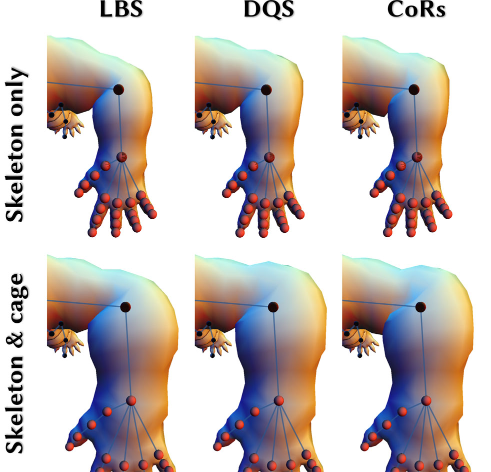
Deformations defined by linearly blending transformation matrices associated to the bones of a control skeleton, also known as Linear Blend Skinning (LBS), appeared long time ago in the literature (Magnenat-Thalmann et al., 1989) and have become extremely popular ever since. LBS suffers from a number of artifacts, most of which come from singular transformation matrices generated by the linear interpolation of rotations. A typical artifact of this kind is the well known candy wrap, which arises at the shoulders of a character when big torsions are applied to its arms. Recent literature has proposed more robust ways to combine transformation matrices. In particular, Kavan and colleagues proposed to blend rotations in the space of Dual Quaternions (DQS), avoiding the generation of candy wrap artifacts at the cost of a minimal overhead in the real-time deformation pipeline (Kavan et al., 2008). Due to their simplicity and intuitiveness, LBS and DQS are de facto standards in skeleton-based deformation. More recent non-linear skinning methods, such as Stretchable and Twistable bones (Jacobson and Sorkine, 2011), Differential Blending (Öztireli et al., 2013) and Elasticity Inspired Deformers (Kavan and Sorkine, 2012) introduce more sophisticated techniques that act on the same basic ingredients, namely rigging weights and affine transformations, to define the pose of the skeleton. Finally, Le and Hodgins (2016) introduced an efficient method designed to avoid the respective artifacts of LBS and DQS, through the definition of a per-vertex Center of Rotation (CoR) derived from an analysis of the skinning weights, and resulting from an optimization targeting as-rigid-as-possible deformations. In our software prototype we incorporated LBS, DQS and CoRs (Figure 2), but our framework can support all previously cited skinning methods, thus promoting a seamless integration with available implementations. Critical to the previously cited methods is the definition of the so-called skinning weights. Various automatic methods aim at defining smooth weights (Baran and Popović, 2007; Wareham and Lasenby, 2008; Jacobson et al., 2011; Jacobson et al., 2012b; Dionne and de Lasa, 2013) or target as-rigid-as-possible deformations under training (Thiery and Eisemann, 2018). While automatic methods generally provide satisfactory results on challenging inputs, artists often need to tune the skinning weights as they target specific effects, and methods allowing for high-level skinning weights editing have been developed recently (Bang et al., 2015; Bang and Lee, 2018). Our method is quite general and has no restrictions on the skinning weights used for deformation, thus allowing for great artistic flexibility.
Cages
Cage-based methods derive directly from the Free Form Deformation (Sederberg and Parry, 1986) and allow to deform a volume bounded by a control mesh. Each point within such volume is defined as a weighted sum of cage vertices, hence its position can be efficiently updated each time the cage is deformed by the user. Control weights are generalized barycentric coordinates, and differ to each other mainly for their smoothness and locality. Several alternatives have been proposed in the literature (Thiery et al., 2018, 2013; Ju et al., 2005; Joshi et al., 2007; Lipman et al., 2007, 2008; Zhang et al., 2014; Hormann and Sukumar, 2008). All methods, with the exception of (Lipman et al., 2008; Ben-Chen et al., 2009), compute skin coordinates as a linear combination of cage vertices, and are seamlessly supported by our framework. Similarly to skeletons, cages can be either automatically computed or manually crafted, thus ensuring a seamless integration with most available implementations. For brevity, we do not review methods for cage generation. We point the reader to the survey of (Nieto and Susín, 2013) for classical literature in the field, and to (Casti et al., 2019) and references therein for a list of more recent algorithms.
Hybrid approaches
Some methods depart from the classical skeleton-based and cage-based deformation paradigms, trying to improve on them on some aspect. Garcia et al. (2013) proposed a hybrid system that seamlessly combines multiple cages and barycentric coordinates. The system is completely devoted to cages only, and does not take into consideration interactions with a skeleton. Mukai and Kuriyama (2016) propose the use of automatically generated bone helpers to enrich the space of deformations of linear blend skinning with secondary motions, enabling the animation of muscles and soft tissues. The system focuses on a very specific problem and does not offer the flexibility granted by a real control cage. Being compatible with LBS, their bone helpers could also be incorporated in our framework. Ju et al. (2008) combined the use of cages and skeletons to avoid the candy wrap artifacts of LBS. Opposite to ours, their system works as an open loop, using the skeleton to pose the cage, and the cage to pose the skin. Similar systems are currently supported by commercial software (e.g. Blender (2018)), but do not really offer the possibility to seamlessly combine deformations defined on the skeleton with others defined on the cage in arbitrary order. The combination of skeletons and point handles was explored in (Wang et al., 2015). Jacobson et al. (2011) proposed a system where skeleton, cage and point handles are all integrated into the same framework. Their system require the simultaneous definition of all structures (see Equation 1 in the original paper), and is based on the use of the same coordinates at all levels, without permitting the use of manually painted weights, or different weights for different handles. Moreover, the skeleton and the cage are part of the same meta-structure and must be jointly animated: manipulating the skeleton (resp. the cage) will not induce a deformation of the cage (resp. the skeleton), contrary to what we aim at. All in all, previous techniques cannot offer the flexibility of our technique, that is, switching seamlessly from one structure to the other while always relying on the optimization framework to update the other structure appropriately. Finally, combining deformation rigs has been used for a long time in specialized industrial scenarios. In particular, on-surface facial rigs are often superimposed on the skeleton rigs that control the head orientation. However, this scenarios typically come with a fixed prioritization policy e.g., facial rigs defined in the local frame of the face, which itself undergoes a single rigid transform stemming from the neck bone. The scenarios we address is more challenging, as both structures compete to control global and non-rigid deformations that happen simultaneously.
Exploration of shape space
Our method is loosely related to methods based on the analysis of 3D shapes and subsequent structure aware deformation, which have the main intent to explore the space of shapes similar to a reference mesh (Figure 8). To this end, our real time deformation tool complements classical methods based on feature curves (Gal et al., 2009), bounding envelopes (Zheng et al., 2011) or semantic handles (Yumer et al., 2015), without exposing any significant technical overlap.
3. Background
We take as input a polygonal mesh , together with a skeleton rigged to , and a cage surrounding . We set our working structures at rest pose by initializing , and ; note that , and can evolve because of editing, as discussed in the next section. Our method uses only the set of vertices of meshes and is oblivious of their connectivity. For this reason, whenever no ambiguity arises, we will overload the same symbol to denote both a mesh and its set of vertices.
Skeleton-based deformation
As customary, instead of representing the skeleton explicitly, we consider the set of rigid transformations that determine a given pose. Each transformation , is associated to the -th bone of and represents a rotation around one of its endpoints, which affects all the sub-skeleton below the given joint in the bones hierarchy. At rest pose, all transformations are set to identity. The skeleton is rigged to through a (sparse) matrix of weights , where each entry defines the influence of the -th bone of on -th vertex of .
A general skeleton-based deformation (a.k.a. skinning) has the following form
| (1) |
where is the deformed (current) mesh. For instance, LBS is encoded vertex-wise by
| (2) |
which is often presented in the following form where the linear part applied to the vertex is separated from the translation part
| (3) |
while DQS is encoded similarly
| (4) |
where DQblend is the proper function to blend transformations represented via dual quaternions, while and denote the -th rows of and , respectively.
The recently introduced CoR method (Le and Hodgins, 2016) is slightly different from other methods, in the sense that it makes use of an additional parameter derived from a cross analysis of the mesh geometry and the skinning weights: a per-vertex Center of Rotation (CoR). This CoR associated with vertex is computed as
| (5) |
denoting a distance between the sets of weights of vertex and vertex .
Given the CoR associated with vertex , and computing the linear part applied to the mesh vertex using quaternion blending of the bone rotations , the translation applied to the vertex is computed as
Since the CoR computation depends only on the skinning weights, vertices with similar skinning weights have similar CoRs and are therefore transformed by the same rigid transformation.
Overall, the (run time) deformation of vertex by the CoRs method can be summarized as
| (6) |
where DQBlendRot reurns the linear part of the matrix DQBlend as defined above.
Our method is compliant with all skinning methods mentioned in Section 2, and any which requires only the rest pose location of the joints of the skeleton (or centers of rotation derived from the rest pose mesh as done in the CoRs method).
Cage-based deformation
The cage controls via a (sparse) matrix of barycentric coordinates , where entry is the barycentric coordinate of mesh vertex with respect to cage vertex . We require deformation to be given vertex-wise by the standard linear equation
| (7) |
where represents the (deformed) position of vertex of when the cage vertices are set at (edited) positions . This equation is compliant with all barycentric coordinates reviewed in Section 2, except the Geeen coordinates (Lipman et al., 2008) and the Variational Harmonic Maps (Ben-Chen et al., 2009), which require also face normals that set a non-linear relation between the cage and the skin. Indeed, our method is not compliant with the latter two techniques. Note that Equation 7 does not refer to any rest position for either the cage or the skin. By convention, we assume that we have a rest pose for the cage , when its vertices are at positions where equality holds. Namely, the rest pose of the cage induces the rest pose of the skin. In fact, this is the usual setting from which the barycentirc coordinates are obtained.
4. Method
In the following, we will refer to six structures, namely: the skin , the skeleton and the cage at rest pose, together with their deformed counterparts , and at current pose. Our method aims at reaching consensus among these structures upon any interleaved sequence of skeleton-based and cage-based deformations. Our system makes it possible to edit any structure, assuming the sets of skinning weights and barycentric coordinates remain constant. Note that is induced by via skinning when contains just identity transformations; and is induced by via barycentric coordinates: these invariants set the consensus at rest pose and will be maintained throughout. Unfortunately, if a mesh is induced via skinning by a skeleton , there may not exist a cage that induces , and vice-versa. We address this issue by synchronizing and so that they produce similar skins: is obtained through skinning, with a process that incorporates also .
User interaction.
The user can operate on three of the six structures defined above, namely the user can edit:
-
•
the current pose of the skeleton;
-
•
the cage at rest pose;
-
•
the cage at current pose.
Direct editing of either the skin (resp. skeleton) at rest pose is not considered, as this operation is inherent to modeling (resp. rigging) the input shape; it would be straightforward to include them in our framework, though. Note that the roles of the skeleton and the cage are not fully symmetric: while the former can modify only the current pose of the skin, the latter can modify both current and rest poses. From the user point of view, editing the rest pose means adapting a different skin to the rigging, which remains untouched.
When executed, the three user interactions outlined above trigger a set of sync operations, automatically handled by the system. Specifically:
-
•
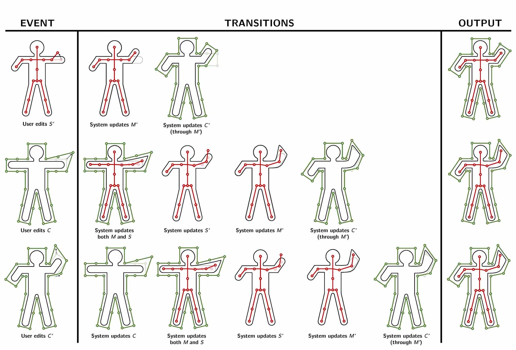
if is edited, then both and will follow, while no change will occur to any structure in the rest pose (Figure 3, top);
-
•
if is edited, then will follow, will be adjusted to the new skin and the current set of transformations will be adjusted accordingly, inducing a new current pose and a new skin – the current cage will be also updated (Figure 3, middle);
-
•
if is edited, we have the most complicated situation: changes to will be reflected to ; while all other modifications will occur as in the previous case up to itself, in a closed loop (Figure 3, bottom).
In order to get a consistent result in all cases, we must synchronize the different structures, as explained in the following.
Synchronization.
We achieve synchronization among the six structures in the two poses by introducing a set of transitions, which reflect editing among them and are summarized in Figure 4:
-
•
is the standard skinning from Equation 1;
-
•
is the standard application of barycentric coordinates from Equation 7;
-
•
adjusts the centers of rotations of on a modified skin at rest pose – we call it the skeleton updater (SkelUp);
-
•
finds a consensus between the current poses of the skeleton and the cage, – we call it the cage updater (CageUp);
-
•
reflects the direct editing on the current pose to the cage at rest pose – we call it the Reverse cage deformer (CageRev). We must guarantee that the current cage determined from editing by the user coincides with the current cage resulting from the transition , as induced by the rest cage modified by . In order to achieve this result, we must set this transition in a proper way.
No other direct transitions are considered. For instance, there is no direct transition from to . This is a specific design choice, which determines the clockwise central cycle in Figure 4: no matter where interaction starts, we propagate its effects through this cycle to maintain all four structures synchronized.
The four structures in the central cycle of the diagram are synchronized after each editing operation so that the central cycle remains at a steady state. The non-standard operations in the above list are detailed in the following subsections.
4.1. Cage Updater
The transition corresponds to the algorithm denoted CageUp in Figure 4. When the skeleton is modified, we skin to obtain and update accordingly. More precisely, we seek a cage that generates a skin as close as possible to , according to the (static) barycentric coordinates .
As already observed in Section 4 this problem may (and in general does not) admit an exact solution. To avoid solving a least squares problem of the size of , we apply the MaxVol relaxation proposed in (Thiery et al., 2012). During pre-processing we extract a subset of vertices of with the same cardinality of the vertices of . Vertices are selected so as to result in a matrix of coordinates with the highest volume. Then, we consider the corresponding set in the current mesh , and we solve the linear system
| (8) |
where is the submatrix of corresponding to the vertices of . Note that this is a square system having same size of (which is assumed to be much smaller than ). The system is invertible and remains fixed throughout; we factorize it once and efficiently solve it with back-substitution in real-time. Besides performances, as shown in (Thiery et al., 2012) the resulting fitted cages are also more stable than the cages fitted to the full geometry using a least squares approach. Also consider that the purpose of the CageUp is not to best reconstruct the mesh as a function of the fitted cage, but rather to provide the user with a stable cage that nicely envelopes it and aids interaction, therefore the use of the relaxation is appropriate.

4.2. Skeleton Updater
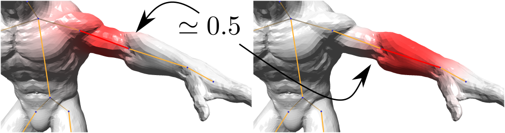
The transition corresponds to the algorithm denoted SkelUp in Figure 4. When a deformation of is performed – either directly or as the result of deforming cage – we update the skeleton at rest pose and propagate it down the skinning pipeline. Indeed, when the cage stretches limbs or creates a bulge on the skin, the position of the skeleton joints, which act as centers of rotation during skinning, must be repositioned to avoid artifacts (Figure 5). In other words, we need this to preserve the semantic relation between the skeleton joints and their position relative to the skin.
We address this issue by introducing a new relation between the cage vertices and the position of skeleton joints. This relation is computed once and for all in pre-processing, and allows to express the position of skeleton joints at rest pose as a linear combination of the cage vertices, giving us the ability to readily update/refit the skeleton in real-time. Note that this update is not limited to a simple global registration, but rather can change the local geometry of the skeleton (e.g. stretching/shrinking its bones).
Skeleton Updater weights
All computations in the following are peformed only once in the initial pose and involve and . We first identify to which mesh vertices a joint corresponds to, by defining a (discrete) joint localization function for each joint of . These functions depend only on the skinning weights and are defined vertex-wise on as follows
| (9) |
with (we use in our implementation). Function takes value in rigid regions (i.e., for and ) and larger values as approaches , i.e., near the joint, where the skinning weights blend the most (see Figure 6).
Next, we use our joint localization functions to define barycentric coordinates for the joints positions w.r.t. the cage, and exploit them to transform the joints along with the skin with cage deformation. Specifically, we first compute Mean Value Coordinates for the joints rest pose locations w.r.t. the input mesh, which we localize around the articulation using the localization function. Note that the resulting weights are not valid barycentric coordinates at this step. The joints barycentric coordinates are then defined as
| (10) |
where the free index is varying over the vertices of and MEC denotes the projection of input masses in to the set of valid barycentric coordinates for i.e., verifying linear precision: and partition of unity: – and closest to the input masses as the output barycentric coordinates maximize the cross entropy, following the strategy introduced by Hormann and Sukumar (2008)
| (11) | |||||
One may see this construction as deriving barycentric coordinates for the input articulations w.r.t. the input cage through the combination of (i) the input cage coordinates, and (ii) the localization function derived from the input skinning weights, which allows us expressing (once fixed) the articulations as a linear combination of the cage vertices, since
| (12) |
where is computed here per line for each joint with constrained rest-pose independently. This construction presents several advantages. In particular, we make no assumption over the set of input coordinates , input skinning weights , or quality of the input mesh. Additionally, the construction is intuitive, since one can simply edit the localization function as an ad-hoc set of weights allowing for the reconstruction of the joint position as a combination of the mesh vertices. Moreover, it is highly efficient and parallelizable.
Skeleton joints refitting
When is deformed, we update the joints of at positions as a linear combination of cage vertices with
| (13) |
where the are the barycentric coordinates described earlier. Note that, after the joints have been relocated, the length and orientation of the bones in the skeleton have been changed; these changes must be reflected on the current skeleton and, consequently to the and . In order to trigger these changes, we update each skinning transformation of by keeping its rotational component unchanged and by recomputing its translational component according to the new joints rest-pose locations. We do so by simply following the hierarchical structure of the skeleton, updating first all roots, and then processing children in an iterative manner, so as to preserve the iteratively deformed skeleton articulations. The effect of updating , hence , propagates down through standard skinning, and the Cage Updater described previously.
CoRs repositioning
As already discussed, the CoRs method makes use of per-vertex centers of rotations for vertices , which are precomputed following Equation 5. Since a manipulation of the cage deforms the rest pose state for the skeletal deformation, we have to reposition the CoRs as well. Fortunately, those are defined as a linear combination of the mesh rest pose vertices . Rewriting Equation 5 in matrix form as , and using the fact that the rest pose mesh is expressed as , we can precompute the matrix when computing the centers of rotation, and reposition them at run time using
| (14) |
Doing so, we assume that the area terms in the surface averaging remain similar (see Equation 5). In fact, this introduces slight differences between the CoRs we obtain after a cage deformation of the rest pose mesh, and the ones one can obtain when recomputing them from scratch, every time the rest pose mesh is changed. However, these differences are minor, and do not impact negatively the quality of the resulting deformation (see Figure 2). In particular, the vertices with similar input skinning weights are still transformed by the same rigid transformation. Lastly, our joints repositioning method is highly compatible in spirit with the CoRs method, as both motivate the use of the cross analysis of the mesh geometry and the skinning weights in the derivation of optimal pivot positions.
4.3. Reverse Cage Deformer
The transition corresponds to the algorithm denoted CageRev in Figure 4. While the user interacts with , we must reflect any modification with a corresponding modification of the rest cage , and such modification must maintain the framework consistent. To do so, we express the generic modification as a function of through the sequence , and we finally reverse this function. In order to obtain a linear problem and achieve efficiency, we compute the above function by assuming LBS throughout. We will discuss at the end of the section how to handle other types of skinning methods.
In order to exploit matrix computation, we linearize all our structures. For the sake of clarity and with abuse of notation for this section only, we use the same symbols as before to denote the linearized structures. We denote the vectors stacking the vertices of the rest and the current cage, respectively; and we denote , , the marices computed as the Kronecker products between their respective matrices as defined previously and the Identity matrix (note that the linearized matrices have sizes , , and , respectively). Moreover, we explicitly represent the skinning components as follows. We denote the vector stacking the current articulations of the skeleton. And we split the skinning rotational and translational component as follows: we denote a matrix composed of matrices on the diagonal (block is the linear part applied to vertex – for LBS, ), and the vector stacking all translation parameters , where, as previously, and are the translation and rotation components of respectively. Therefore, the dynamic rest pose skin , the current skin , and the current cage are obtained by the following formulas
| (15) |
where used, as in section 4.1, to denote all quantities that require only the subset of mesh vertices selected by MaxVol (the cage updater requires the transformed position of those vertices only). We can observe that the third equation is nothing but a matrix expression of Equation 1, where the rotational and translational components of the transformation at each vertex have been separated, following Equation 3.
We aim at computing offsets to apply to the rest cage so as to obtain a resulting offset , which the user wishes to apply to the current cage. Before pursuing the derivation, we stress that the set of Equations 15 is not sufficient for that purpose as, in fact, applying offsets to the skeleton articulations results in changes in the skeletal deformation parameters , since the translation parameters are affected to preserve the skeleton connectivity.
Relating joint offsets and skeletal deformations.
Following (Thiery and Eisemann, 2018), we note that applying an offset to an articulation results in offsets applied to the translations in the following manner
| (16) |
the first equation simply means that the pivot point is updated accordingly, and the second equation simply means that the joint has to be preserved by the transformations of handle and its father both, under preservation of the linear parts of the skeletal deformation . This system can be rewritten as
| (17) |
or, in matrix expression
| (18) |
We note that, while depends on the current skeletal deformation parameters (the linear part ), depends on the topology of the skeleton only, and can safely be inverted once and for all, independently of the current skeletal deformation parameter set.
Relating interaction and deformation cages offsets.
Finally, we can gather the previously derived equations to obtain the linear system
| (19) |
that can be resolved efficiently. Note that when no skeletal deformation is performed i.e., the linear part is composed of Identity matrices only and all translations are null, the current cage and rest cage match (as they should), since is then the identity matrix and is null.
Impact of the MaxVol relaxation
Note that using a subset of the mesh vertices in the cage fitting has several important consequences: First, all matrices in Equation 19 have dimensions bounded by , which results in updates that can be performed in real time on the examples we used, these timings being in this case entirely independent from the mesh size. Secondly, by matching the dimensionality of the cage and the mesh used for inversion, the system in Equation 19 is exactly invertible, and the loop is exact.
We originally tried using all vertices in the inversion process, resulting in an approximate loop. While the approximation was extremely subtle and unnoticeable, the biggest issue was that it resulted in reduced performance: we could not obtain results that were fast enough for a modeling session on large models, as the user had to wait a few seconds when switching from skeleton manipulation to cage manipulation. Note that, if desired, the user could still rely on more vertices than just the ones selected by MaxVol (a good strategy could be to use farthest sampling in the space of cage coordinates of the vertices, as done in (Jacobson et al., 2012a) – Section 3.3); the construction described in this section would remain valid, but the inverse of the matrices would have to be replaced by pseudo-inverses and the loop would be only approximate (rigorously, the manipulation cage is then obtained by least-squares fitting as , which leads to a modified Equation 19 where both terms are multiplied by on their left).
Handling skeletal deformation methods other than LBS
As already emphasized earlier, the Reverse Cage Deformer operator assumes LBS as the skinning deformation method. This will give us indeed an exact result if LBS is the current skinning method, and an approximated result with the other skinning methods. However, since the Reverse Cage Deformer is always applied to small incremental modifications , the approximation error is negligible and hardly noticeable during user interaction. Another possibility is to make use of a ghost mesh that is deformed with LBS and use this ghost mesh to drive the fitting of the interaction cage in the cage updater, regardless of the actual final deformation method. The cage updater CageUp is then not optimal, in the sense that it best fits an LBS deformation of the mesh instead of the actual deformed mesh, but the loop is always exact. Note that only the vertices selected for inversion need to be deformed in the ghost mesh, so this step is negligible in practice. Both options are satisfactory and trivial to implement, and will work well for all skinning methods producing deformations that resemble LBS at large scale (as illustrated in our results featuring DQS and CoRs) since the cage fitting performed by CageUp is a global operation as a result of using global cage weights.
| Model | Verts | Skel | Cage | SkelUp | CageUp | CoR | CageRev | LBS | DQS | CoR |
|---|---|---|---|---|---|---|---|---|---|---|
| joints | handles | preprocess | preprocess | update | update | frame | frame | frame | ||
| Arm (coarse cage) | 2089 | 24 | 28 | 401 | 5 | 1 | 3 | 0.88 | 1.62 | 2.26 |
| Arm (medium cage) | 2089 | 24 | 58 | 417 | 29 | 1 | 20 | 1.61 | 1.53 | 1.63 |
| Arm (fine cage) | 2089 | 24 | 79 | 439 | 45 | 1 | 40 | 2.22 | 1.84 | 2.17 |
| Warrok | 6557 | 64 | 104 | 2672 | 106 | 1 | 83 | 7.81 | 7.66 | 9.51 |
| Ely | 7512 | 64 | 88 | 3018 | 75 | 1 | 56 | 9.24 | 8.73 | 9.99 |
| Airplane | 41425 | 19 | 69 | 3738 | 44 | 5 | 30 | 23.7 | 21.68 | 26.40 |
| Timber Rattlesnake | 120066 | 98 | 44 | 46771 | 32 | 9 | 16 | 50.03 | 39.43 | 52.35 |

5. Results
We have implemented our modeling framework as a single-threaded C++ program. Models have been either manually crafted or downloaded from online repositories such as Adobe Mixamo (2019) and SketchFab (2019). Whenever a control cage was not provided in the original dataset, we used the method proposed in (Casti et al., 2019) to produce one. In case the skinning was missing, we manually created one using Maya (2019). In terms of performances, our hybrid modeling system introduces only negligible overhead with respect to the classical skeleton- and cage-based pipelines, and for moderately complex characters runs in real time with high frame rate even on commodity hardware (Table 1).

Deformation options
A key feature of our hybrid deformation system is its ability to scale across multiple methods for skeleton- and cage-based deformation, which can therefore be chosen from pratictioners depending on their taste and needs. For the skeleton part we implemented the two most popular skeleton-based deformation methods, namely Linear Blend Skinning (Magnenat-Thalmann et al., 1989), Dual Quaternions (Kavan et al., 2008), and the recently introduced CoR (Le and Hodgins, 2016), which combines the positive aspects of the previous two and at the same time avoids their weak points (volume loss for LBS, bulging for DQS). A side by side comparison between these three alternatives is shown in Figure 2. For the skinning weights, although various automatic methods exist in literature (Section 2), industry level deformations often involve carefully designed weights that are manually painted on the surface by skilled artists. Our system is agnostic on the specific weights of choice, and transparently supports both automatic and manual approaches. Rigs are imported into the system using standard formats (i.e. FBX), securing an easy interface with commercial software and publicly available repositories. For the cage part we used the Mean Value Coordinates (Ju et al., 2005) in all our tests, which are internally computed by our framework. Similarly to skeleton weights, alternative barycentric coordinates that obey the linear blend of Equation 7 can be loaded into the system and used in a transparent way. To the best of our knowledge, this includes the vast majority of the known barycentric coordinates that appeared in literature, including the recently proposed coordinates for quad cages (Thiery et al., 2018). Two notable exceptions are the Green Coordinates (Lipman et al., 2008) and the Variational Harmonic Maps (Ben-Chen et al., 2009), which both use a blend equation that involves mesh vertices and face normals, and are therefore not directly applicable to our linear deformation paradigm.
Skeleton updater
In Figure 5 we evaluate our skeleton updater with a synthetic shape, consisting on a straight bar bent at 45/90/135 degrees using LBS. Editing the bar with the cage moves the skeleton away from the correct centers of rotation, and without the skeleton re-fitting procedure described in Section 4.2 extremely evident artifacts arise. Our bone positioning system correctly recovers from all configurations, producing visually plausible deformations. Note that the system is not sensitive to the specific cage being used, and produces valid results both with a regular (left) and irregular (right) cage.
Scale adaptivity
Skeletons and cages may be very dfferent to one another, and are indeed able to control features of the same object at different scales. Our system is able to seamlessly combine skeletons and cages that operate at different levels of detail. In Figure 7 a simple bent arm controlled by a skeleton is further edited with three alternative cages. The coarse cage controls the whole hand, and is used to enlarge it; the medium cage allows to selectively edit each finger, and is used to thicken the thumb; the dense cage contains various control points around the bicep, and is used to inflate it when the arm is bent. All three hybrid deformations are visually plausible and difficult to replicate by acting solely on a skeleton or on a cage.
Hybrid modeling
The principal intent when designing our deformation framework was to offer artists a unique system where they could seamlessly combine multiple deformation paradigms. Starting from an input shape linked to a skeleton and a cage, artists can explore the space of deformations to create a family of similar objects, using the more appropriate tool for each edit. An example of hybrid modeling is given in Figure 8, where several variations of an airplane are produced from a single item. Skeleton bones are used to control the rigid parts the plane (e.g. to bend the core and the wings). Cage handles are used to apply local volumetric deformations, for example to locally inflate parts of the core, or to edit the profile of the wings.
Hybrid Animation
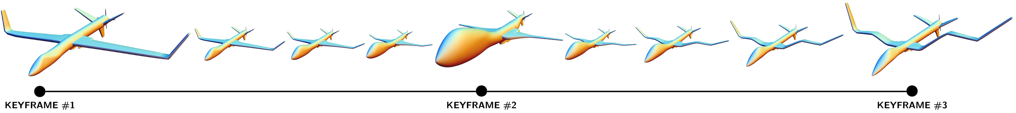
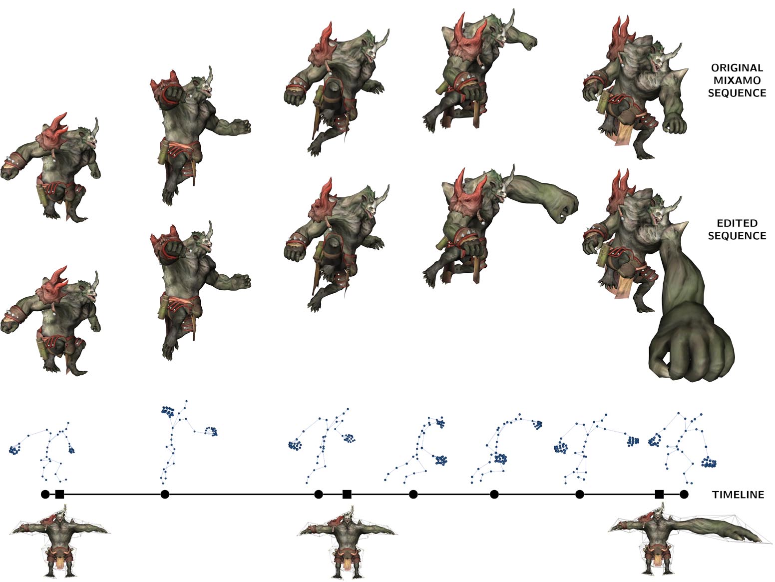
Another interesting application of our framework consists in using the various shapes it produces as keyframes, to guide a computer generated animation sequence. In Figure 9 we show a few interpolated frames of an animation, obtained keyframing some of the airplanes shown in Figure 8. In between frames are generated interpolating bone rotations with Slerp (Dam et al., 1998) and cage vertices linearly. Note that the deformation cage is keyframed, not the manipulation cage . The skeleton updater is therefore required at each reconstruction step (but the update is extremely fast as it is linear in the number of skeleton joints only), but the cage reverse updater is not involved in the process. Following a similar approach legacy animations can be enriched with new effects. In Figure 10 we show a skeleton driven punch sequence downloaded from Adobe Mixamo (mix, 2019), which we enriched with three cage keyframes that inflate the punch at the proper time. Note that a minimal workload is already enough to incorporate in the animation new interesting effects. In this specific case only one manually edited keyframe was used, the other two are simple envelopes of the rest pose, computed with (Casti et al., 2019). Also note that skeletons and cage keyframes are interpolated asynchronously, hence can work on the same character independently and at different levels of detail. Similar results are also shown in Figure 11. We point the reader to the accompanying video to see the actual animations we obtained.
6. Conclusion and future work
We started from the observation that skeleton-based and cage-based deformations control different aspects of shape modeling, and are to a large extent complementary to one another. We therefore proposed a real-time modeling framework based on a novel paradigm that seamlessly combines these structures. We obtained the desired effect by adopting the concept of rest pose and current pose for both skeletons and cages, introducing novel update operators that realize the sync between all these structures. As a result, we operate in a larger deformation space, containing poses that are impossible to obtain by acting solely on a skeleton or a cage.
Our framework is back-compatible with most existing techniques for skeleton-based and cage-based deformation. The only limitation in this sense comes from our assumption of a linear equation for cage-based shape editing (Equation 7). From a technical standpoint, non linear cage-based deformation techniques such as (Lipman et al., 2008) could potentially be incorporated in the system, though at the cost of having more complex algorithms to maintain the sync. Similar considerations can be done for partial cages, such as the ones proposed in (García et al., 2013). We did not perform tests in these directions yet, but it would be interesting to check how this will affect the frame rate and the real-time experience.
Regarding user interaction, the visualization of controllers for both the skeleton and the cage may sometimes clutter the screen, especially for complex characters requiring numerous skeleton bones and complex control cages. We envisage a potential improvement by adopting a dynamic rendering of the controllers, that fades away from the mouse position.
We believe that our contribution could support advanced deformation control. In our future work, we plan to extend the framework with more controllers (e.g. point handles) which we can incorporate with the same approach to synchronization, while remaining oblivious on the specific technique used for their implementation.
References
- (1)
- mix (2019) 2019. Adobe Mixamo dataset. https://www.mixamo.com.
- may (2019) 2019. Autodesk Maya. https://www.autodesk.com/products/maya/overview.
- sf (2019) 2019. SketchFab. https://sketchfab.com.
- Bang et al. (2015) Seungbae Bang, Byungkuk Choi, Roger Blanco i Ribera, Meekyoung Kim, Sung-Hee Lee, and Junyong Noh. 2015. Interactive rigging with intuitive tools. In Computer Graphics Forum, Vol. 34. Wiley Online Library, 123–132.
- Bang and Lee (2018) Seungbae Bang and Sung-Hee Lee. 2018. Spline Interface for Intuitive Skinning Weight Editing. ACM Transactions on Graphics (TOG) 37, 5 (2018), 174.
- Baran and Popović (2007) Ilya Baran and Jovan Popović. 2007. Automatic rigging and animation of 3d characters. ACM Transactions on graphics (TOG) 26, 3 (2007), 72.
- Ben-Chen et al. (2009) Mirela Ben-Chen, Ofir Weber, and Craig Gotsman. 2009. Variational harmonic maps for space deformation. ACM Transactions on Graphics (TOG) 28, 3 (2009), 34.
- Blender Online Community (2018) Blender Online Community. 2018. Blender - a 3D modelling and rendering package. Blender Foundation, Blender Institute, Amsterdam. http://www.blender.org
- Casti et al. (2019) Sara Casti, Marco Livesu, Nicolas Mellado, Nadine Abu Rumman, Riccardo Scateni, Loïc Barthe, and Enrico Puppo. 2019. Skeleton Based Cage Generation Guided by Harmonic Fields. Computers & Graphics (2019). https://doi.org/10.1016/j.cag.2019.04.004
- Dam et al. (1998) Erik B Dam, Martin Koch, and Martin Lillholm. 1998. Quaternions, interpolation and animation. Vol. 2. Citeseer.
- Dionne and de Lasa (2013) Olivier Dionne and Martin de Lasa. 2013. Geodesic voxel binding for production character meshes. In Proceedings of the 12th ACM SIGGRAPH/Eurographics Symposium on Computer Animation. ACM, 173–180.
- Gal et al. (2009) Ran Gal, Olga Sorkine, Niloy J Mitra, and Daniel Cohen-Or. 2009. iWIRES: an analyze-and-edit approach to shape manipulation. In ACM Transactions on Graphics (TOG), Vol. 28. ACM, 33.
- García et al. (2013) Francisco González García, Teresa Paradinas, Narcís Coll, and Gustavo Patow. 2013. *Cages:: A Multilevel, Multi-cage-based System for Mesh Deformation. ACM Trans. Graph. 32, 3 (2013), 24:1–24:13.
- Hormann and Sukumar (2008) Kai Hormann and Natarajan Sukumar. 2008. Maximum entropy coordinates for arbitrary polytopes. In Computer Graphics Forum, Vol. 27. Wiley Online Library, 1513–1520.
- Jacobson et al. (2012a) Alec Jacobson, Ilya Baran, Ladislav Kavan, Jovan Popović, and Olga Sorkine. 2012a. Fast automatic skinning transformations. ACM Transactions on Graphics (TOG) 31, 4 (2012), 77.
- Jacobson et al. (2011) Alec Jacobson, Ilya Baran, Jovan Popović, and Olga Sorkine. 2011. Bounded biharmonic weights for real-time deformation. In ACM Transactions on Graphics (TOG), Vol. 30. 78.
- Jacobson et al. (2014) Alec Jacobson, Zhigang Deng, Ladislav Kavan, and JP Lewis. 2014. Skinning: Real-time Shape Deformation. In ACM SIGGRAPH 2014 Courses.
- Jacobson and Sorkine (2011) Alec Jacobson and Olga Sorkine. 2011. Stretchable and twistable bones for skeletal shape deformation. ACM Transactions on Graphics (TOG) 30, 6 (2011), 165.
- Jacobson et al. (2012b) Alec Jacobson, Tino Weinkauf, and Olga Sorkine. 2012b. Smooth shape-aware functions with controlled extrema. In Computer Graphics Forum, Vol. 31. Wiley Online Library, 1577–1586.
- Joshi et al. (2007) Pushkar Joshi, Mark Meyer, Tony DeRose, Brian Green, and Tom Sanocki. 2007. Harmonic coordinates for character articulation. In ACM Transactions on Graphics (TOG), Vol. 26. ACM, 71.
- Ju et al. (2005) Tao Ju, Scott Schaefer, and Joe Warren. 2005. Mean value coordinates for closed triangular meshes. In ACM Transactions on Graphics (TOG), Vol. 24. ACM, 561–566.
- Ju et al. (2008) Tao Ju, Qian-Yi Zhou, Michiel van de Panne, Daniel Cohen-Or, and Ulrich Neumann. 2008. Reusable Skinning Templates Using Cage-based Deformations. ACM Trans. Graph. 27, 5, Article 122 (2008), 10 pages.
- Kavan et al. (2008) Ladislav Kavan, Steven Collins, Jiří Žára, and Carol O’Sullivan. 2008. Geometric skinning with approximate dual quaternion blending. ACM Transactions on Graphics (TOG) 27, 4 (2008), 105.
- Kavan and Sorkine (2012) Ladislav Kavan and Olga Sorkine. 2012. Elasticity-Inspired Deformers for Character Articulation. ACM Transactions on Graphics (proceedings of ACM SIGGRAPH ASIA) 31, 6 (2012), 196:1–196:8.
- Le and Hodgins (2016) Binh Huy Le and Jessica K Hodgins. 2016. Real-time skeletal skinning with optimized centers of rotation. ACM Transactions on Graphics (TOG) 35, 4 (2016), 37.
- Lipman et al. (2007) Yaron Lipman, Johannes Kopf, Daniel Cohen-Or, and David Levin. 2007. GPU-assisted positive mean value coordinates for mesh deformations. In Symposium on geometry processing.
- Lipman et al. (2008) Yaron Lipman, David Levin, and Daniel Cohen-Or. 2008. Green coordinates. ACM Transactions on Graphics (TOG) 27, 3 (2008), 78.
- Magnenat-Thalmann et al. (1989) N Magnenat-Thalmann, R Laperrière, and D Thalmann. 1989. Joint-dependent local deformations for hand animation and object grasping. In Proceedings on Graphics interface’88. Canadian Information Processing Society, 26–33.
- Mukai and Kuriyama (2016) Tomohiko Mukai and Shigeru Kuriyama. 2016. Efficient dynamic skinning with low-rank helper bone controllers. ACM Transactions on Graphics (TOG) 35, 4 (2016), 36.
- Nieto and Susín (2013) Jesús R Nieto and Antonio Susín. 2013. Cage based deformations: a survey. In Deformation models. Springer, 75–99.
- Öztireli et al. (2013) A. Cengiz Öztireli, Ilya Baran, Tiberiu Popa, Boris Dalstein, Robert W. Sumner, and Markus Gross. 2013. Differential Blending for Expressive Sketch-Based Posing. In Proceedings of the 2013 ACM SIGGRAPH/Eurographics Symposium on Computer Animation (SCA ’13). ACM, New York, NY, USA.
- Sederberg and Parry (1986) Thomas W Sederberg and Scott R Parry. 1986. Free-form deformation of solid geometric models. ACM SIGGRAPH computer graphics 20, 4 (1986), 151–160.
- Thiery and Eisemann (2018) J-M Thiery and Elmar Eisemann. 2018. ARAPLBS: Robust and Efficient Elasticity-Based Optimization of Weights and Skeleton Joints for Linear Blend Skinning with Parametrized Bones. 37, 1 (2018), 32–44.
- Thiery et al. (2018) Jean-Marc Thiery, Pooran Memari, and Tamy Boubekeur. 2018. Mean value coordinates for quad cages in 3D. ACM Transactions on Graphics (Proc. SIGGRAPH 2018) (2018).
- Thiery et al. (2012) Jean-Marc Thiery, Julien Tierny, and Tamy Boubekeur. 2012. CageR: Cage-Based Reverse Engineering of Animated 3D Shapes. Comput. Graph. Forum 31, 8 (2012), 2303–2316.
- Thiery et al. (2013) Jean-Marc Thiery, Julien Tierny, and Tamy Boubekeur. 2013. Jacobians and Hessians of Mean Value Coordinates for Closed Triangular Meshe. The Visual Computer (2013), 1–15.
- Wang et al. (2015) Yu Wang, Alec Jacobson, Jernej Barbič, and Ladislav Kavan. 2015. Linear subspace design for real-time shape deformation. ACM Transactions on Graphics (TOG) 34, 4 (2015), 57.
- Wareham and Lasenby (2008) Rich Wareham and Joan Lasenby. 2008. Bone glow: An improved method for the assignment of weights for mesh deformation. In International Conference on Articulated Motion and Deformable Objects. Springer, 63–71.
- Yumer et al. (2015) Mehmet Ersin Yumer, Siddhartha Chaudhuri, Jessica K Hodgins, and Levent Burak Kara. 2015. Semantic shape editing using deformation handles. ACM Transactions on Graphics (TOG) 34, 4 (2015), 86.
- Zhang et al. (2014) Juyong Zhang, Bailin Deng, Zishun Liu, Giuseppe Patanè, Sofien Bouaziz, Kai Hormann, and Ligang Liu. 2014. Local Barycentric Coordinates. ACM Trans. Graph. 33, 6 (2014), 188:1–188:12.
- Zheng et al. (2011) Youyi Zheng, Hongbo Fu, Daniel Cohen-Or, Oscar Kin-Chung Au, and Chiew-Lan Tai. 2011. Component-wise controllers for structure-preserving shape manipulation. In Computer Graphics Forum, Vol. 30. Wiley Online Library, 563–572.