Time-dependent Ginzburg-Landau treatment of RF Magnetic Vortices in Superconductors: Vortex-Semiloops in a Spatially Nonuniform Magnetic Field
Abstract
We apply time-dependent Ginzburg Landau (TDGL) numerical simulations to study the finite frequency electrodynamics of superconductors subjected to intense rf magnetic field. Much recent TDGL work has focused on spatially uniform external magnetic field and largely ignores the Meissner state screening response of the superconductor. In this work, we solve the TGDL equations for a spatially non-uniform magnetic field created by a point magnetic dipole in the vicinity of a semi-infinite superconductor. A novel two-domain simulation is performed to accurately capture the effect of the inhomogeneous applied fields and the resulting screening currents. The creation and dynamics of vortex semiloops penetrating deep into the superconductor domain is observed and studied, and the resulting third-harmonic nonlinear response of the sample is calculated. The effect of point-like defects on vortex semi-loop behaviour is also studied. This simulation method will assist our understanding of the limits of superconducting response to intense rf magnetic fields.
I Introduction
Superconductor technology is widely used in industrial applications where high current and low loss are required. With technological advancements in the fabrication of high quality superconducting materials and significant reduction in cryocooler prices, superconductor-enabled devices like Magnetic Resonance Imaging (MRI), high performance microwave and radio frequency (RF) filters, low-noise and quantum-limited amplifiers, or fast digital circuits based on rapid single flux quantum (RSFQ) logic devices became feasible Seidel (2015); SC_ .
Superconducting Radio Frequency (SRF) cavities Aune et al. (2000); Padamsee et al. (2008) used in new generation high energy particle accelerators is an example of the large scale usage of superconductor technology. Nb is the most dominant material used in SRF applications because it has the highest superconducting critical temperature () and super-heating field () among the elemental superconductors at ambient pressure while being a good heat conductor at typical SRF operating temperatures Singer (2015). During normal operation an SRF cavity is subjected to high rf magnetic field parallel to the internal superconducting surface. One of the key objectives in SRF cavity operation is to maximize the accelerating gradient of the machine while minimizing the dissipated power in the cavities. However, these cavities remain susceptible to a number of issues including enhanced losses due to trapped magnetic flux Martinello et al. (2015) and the existence of the point-like surface defects Ge et al. (2010); Iwashita et al. (2008). The maximum gradient operating conditions are often limited by extrinsic problems. One limiting scenario is that a surface defect can facilitate the entrance of vortex-semiloops which can later be trapped due to the impurities within the bulk of the cavity Gurevich and Ciovati (2008). The energy dissipated due to the dynamics of these vortex semiloops under the influence of rf currents could be the limiting factor on the ultimate performance of the SRF cavity. This phenomenon cannot be simulated unless the effects of the screening currents and fields on the superconducting order parameter are included self-consistently.
This work is motivated by results for third-harmonic generation from a near-field microwave microscope utilized on Nb surfaces Lee et al. (2005); Mircea et al. (2009); Tai et al. (2011, 2013, 2014a, 2015); Oripov et al. (2019). In this experiment, a magnetic writer probe from a conventional magnetic recording hard-disk drive is used to create a high-intensity, localized, and inhomogeneous rf magnetic field on the surface of a Nb superconducting sample. This probe applies a localized field oscillating at microwave frequency, and measures the sample’s fundamental Tai et al. (2014b) and harmonic rf response. In the experiment, the third-harmonic response and its dependence on the applied rf magnetic field amplitude and the temperature of the sample was studied. Preliminary results of TDGL modeling and comparison to experimental data was published in Oripov et al. (2019).
In this work, numerical solutions of the time-dependent Ginzburg Landau (TDGL) equations are obtained for a superconductor subjected to a spatially nonuniform applied rf magnetic field, and the effect of boundary conditions on the accuracy of the results is investigated. First, the Ginzburg-Landau (GL) theory and its range of validity is discussed in section II. Secondly, the TDGL equations and the normalization used in this paper are presented in detail in section III. Then, the implementation of the TDGL simulation in COMSOL Multiphysics simulation software with all appropriate boundary conditions is summarized in section IV. Later, in section IV.1 a two-domain simulation capable of correctly modeling spatially nonuniform magnetic fields and the response screening currents of the superconductor is described, and simple examples are presented to demonstrate the validity of the two-domain model. Next, in section V, an application of the two-domain simulation is presented, where vortex-semiloops created by a strongly inhomogeneous field distribution are simulated. The time evolution of the vortex-semiloops, their dependence on the magnitude of the rf magnetic field, and their interaction with a localized defect is studied. Finally, in section V.4, a more general case where the vortex-semiloops are created in a superconductor surface when a uniform rf magnetic field is applied parallel to the surface of the superconductor is presented, and the results are discussed. We then discuss future work in section VI and conclude the paper.
II Ginzburg-Landau Theory
The Ginzburg-Landau (GL) theory is a generic macroscopic model appropriate for understanding the electrodynamic response of superconductors subjected to static magnetic fields and currents in the limit of weak superconductivity Landau and Ginzburg (1950). GL generalizes the theory of superconductivity beyond BCS by explicitly considering inhomogeneous materials, including surfaces, interfaces, defects, vortices, etc.
The GL equations are differential equations which relate the spatial variation of the order parameter to the magnetic vector potential and the current in a superconductor. GL starts with an expression for the free energy density of a superconductor in terms of position-dependent order parameter and vector potential Ginzburg and Landau (2009):
| (1) |
Here, and are the temperature and position-dependent phenomenological expansion parameters, is the mass of the Cooper pair, is the charge of the Cooper pair, is the amplitude of the externally applied magnetic field, and .
Taking variational derivatives and minimizing the free energy with respect to and leads to the coupled Ginzburg-Landau equations Cyrot (1973); Tinkham (2004):
| (2) |
| (3) |
Apart from the TDGL model, the Bogoliubov-de Gennes (BdG) equations Bogoliubov (1958a, b); Gennes (1964, 1999), Gorkov’s Green function method Abrikosov et al. (1975); Kopnin (2001); Gor’kov (1958), the Matsubara formalism Eilenberger (1968); Ehrenreich et al. (1983) or Usadel’s equations Usadel (1970) can be used to study inhomogeneous superconductors Flokstra (2010). We shall utilize TDGL because of its relative simplicity and the physical insights it offers compared to these other more microscopic approaches.
III Time-Dependent Ginzburg Landau (TDGL) Equations and Normalization
The GL equations are static, thus cannot be used to study the temporal evolution of the order parameter and the screening currents. In 1966, Schmid proposed a time-dependent generalization of the GL equations that could be utilized to study the dynamics of the order parameter Schmid (1966). Gor’kov and Eliashberg derived a similar equation Gor’kov and Eliashberg (1968), but noted that for the case of a gapped superconductor, there exists a singularity in the density of states vs energy spectrum which prohibits expanding various quantities in powers of the gap .
Gor’kov limited the use of TDGL to gapless superconductors, or to materials with magnetic impurities or other pair-breaking mechanisms that would round off the singularity in the BCS density of states Tinkham (2004). Proximity to a boundary with a normal metal, along with strong external magnetic fields and currents can also lead to gapless superconductivity before completely destroying it. Of relevance to the case of SRF cavities, numerous researchers have noted a substantial reduction in the singularity, and broadening of the density of states spectrum, under SRF operating conditions Gurevich and Kubo (2017); Kubo and Gurevich (2019) or with various types of impurities and imperfections at the surface Dynes et al. (1978, 1984); Zasadzinski (2003); Balatsky et al. (2006); Proslier et al. (2008). Such conditions would also justify the use and relevance of the TDGL equations under these circumstances.
In order to extend the validity of the TDGL formalism to gapped superconductors, a generalized version of TDGL (gTDGL) was proposed Kramer and Watts-Tobin (1978); Vodolazov et al. (2005). In gTDGL, the effects of a finite inelastic electron scattering time are considered. gTDGL is valid for a superconductor in the dirty limit, but does not require strong limitations such as a large concentration of magnetic impurities and/or gapless superconductivity Kopnin (2001). Nevertheless, both TDGL and gTDGL are not microscopic theories, thus some of the parameters of the model are difficult to determine precisely for a given material of interest . For this reason we focus on semi-quantitative results and use the phenomenological TDGL equations mainly to give insight into the signals created by our near-field microwave microscope Oripov et al. (2019). Future work will explore the order parameter dynamics under gTDGL. In addition, questions of validity and relevance of the solution to the TDGL equations outside of the range in which they are derived remain.
TDGL numerical simulations have been employed on a broad variety of problems Cyrot (1973); Blatter et al. (1994); Aranson and Kramer (2002). We note that TDGL was previously used to study vortex dynamics and V-I characteristics of 2-D rectangular thin films Machida and Kaburaki (1993), vortex entry in the presence of twin boundaries Gropp et al. (1996) and the vortex dynamics under ac magnetic field in mesoscopic superconductors Hernández and Domínguez (2008). TDGL was also used to study the dynamics of vortex loops created by a static magnetic dipole Berdiyorov et al. (2013) which is similar to the results discussed in this work. More recently, the TDGL formalism was used to estimate the strength of the Kerr effect in a superconductor when a short light pulse is applied Robson et al. (2017).
Often a three dimensional problem is simplified by assuming that the sample is infinite in the direction parallel to the externally applied magnetic field, thus reducing the 3D problem to a 2D one Gropp et al. (1996); Sardella et al. (2006); Alstrøm et al. (2011). Moreover, much published work done using numerical solutions to the TDGL equations involve problems with a spatially uniform external magnetic field and use a single (entirely superconducting) domain for the simulation. However, this assumption ignores the effect that the screening currents would have at the surface, which is one of the most important aspects of the problem that we investigate.
Here we give a brief motivation for the origins of the TDGL equations. Once the GL free energy is known in its functional form (Eq. 1), the relaxation dynamical equation can be written by considering how the order parameter evolves after being slightly disturbed from its equilibrium value Kopnin (2001); Rogalla (2011):
| (4) |
where plays the role of a friction coefficient. Here, the scalar electric potential is included to make the equation describing the dynamics of the superconducting order parameter gauge invariant. The TDGL equations are then derived through the variational derivatives of the GL free energy equation (Eq. 1) with respect to and and are given as follows Schmid (1966); Hernández and Domínguez (2002); Alstrøm et al. (2011):
| (5) |
| (6) |
where is the time-dependent order parameter, is the magnetic vector potential, is the externally applied magnetic field, is the scalar electric potential, is the phenomenological electron diffusion coefficient given by Cyrot (1973) with being the Fermi velocity and being the quasi-particle mean free path Aranson et al. (2001), is the electric conductivity of the normal (non-superconducting) state. It is evident from Eq.(5) that and can also be written as , where is a characteristic time for the relaxation of the GL order parameter Hernández and Domínguez (2002) . Here, and , where is the zero temperature GL coherence length.
Eq.(5) was first proposed by Schmid Schmid (1966), following the derivation of the GL equation from BCS Bardeen et al. (1957a, b) by Gor’kov Gor’kov and Eliashberg (1968). Eq.(6) is Ampere’s law , where is the normal current and the supercurrent is defined in Eq.7 .
The superconducting current can be obtained from the expectation value of the momentum operator for a charged particle in a magnetic field:
| (7) |
The TDGL equations are invariant under the following change of gauge Alstrøm et al. (2011):
| (8) |
| (9) |
| (10) |
where is any (sufficiently smooth) real-valued scalar function of position and time. One can fix the gauge as in order to effectively eliminate the electric potential at all times Alstrøm et al. (2011); Robson et al. (2017).
It is useful to introduce dimensionless variables (denoted by twiddles ) to simplify the simulation and normalize Eqs. 5 and 6: The order parameter is scaled according to , where is the bulk superfluid density at zero temperature in the absence of external magnetic field, and . The spatial coordinates are scaled according to the zero temperature GL penetration depth , so that , thus 111Note that the zero temperature GL coherence length can also be used as a normalization length scale (See Ref. Gropp et al. (1996); Peng and Cai (2017)). Time is scaled according to the characteristic time for the relaxation of the vector potential , where 222This time scale is also used in Refs. Gropp et al. (1996); Hernández and Domínguez (2002); Hernández et al. (2007); Alstrøm et al. (2011); Blair and Hampshire (2018) and is the normal state conductivity at 0K (as opposed to the conductivity of non-superconducting current at any temperature denoted as ). The temperature is scaled according to the critical temperature of the superconductor , . The vector potential where is the magnetic flux quantum. The superconductor current is scaled in terms of , , where is the critical current density at and , and is the GL parameter and is defined as the ratio of two characteristic length scales . The normal state conductivity is scaled with its zero temperature value and since it is nearly constant in the temperature range of interest for Nb, it is set to . The ”normalized friction coefficient” is defined as the ratio between the two characteristic time scales and , Hernández and Domínguez (2002); Blair and Hampshire (2018) and is proportional to defined in Eq.4 . For cases when the source of externally applied magnetic field is outside of the superconducting domain, the term in Eq.(6) should be dropped because everywhere within the superconducting domain.
Rewriting Eq.(5) and Eq.(6) using the newly introduced dimensionless quantities and dropping ” ” we have :
| (11) |
| (12) |
| (13) |
Defects (such as pinning sites) can be introduced into the model via spatial variation of the GL coefficient . Such defects could be due to spatial variation of temperature , critical temperature and/or spatial variation of the mean free path . One can calculate the vortex pinning potential created by these kinds of disorder using the method outlined in Blatter et al. (1994). The pinning coefficient dictates the maximum possible value for the superfluid density at a given location and temperature in the absence of external magnetic field.
In this work we are interested in studying the effects of some common SRF surface defects, such as lossy Nb-oxides and metallic Nb-hydrides near the surface of Nb Gurevich (2017). These types of defects are either non-superconducting or have lower critical temperature than Nb. Such metallic inclusions, or the effect of nonzero temperature, can be specified through Sadovskyy et al. (2015); Geurts et al. (2009); Hernández and Domínguez (2008); Miyamoto and Hikihara (2004); Aftalion et al. (2001) which can range from (strong order parameter suppression) to (full superconductivity).
To numerically simulate the superconducting domain, we must specify the boundary conditions for the order parameter, current density, and vector potential. In this work only the superconductor-insulator boundary is considered. Any current passing through the boundary between a superconducting domain and vacuum/insulator would be nonphysical, thus on the boundary of the superconducting domain we expect:
| (14) |
Here is unit vector normal to the boundary, and since we expect Eq.(13) to be true even when and the first boundary condition is Gennes (1999); Hernández and Domínguez (2002); Alstrøm et al. (2011); Blair and Hampshire (2018):
| (15) |
Likewise when both and , to satisfy Eq.( 14):
| (16) |
leading to
| (17) |
The third condition generally used is the continuity of magnetic field across an interface.
| (18) |
where is the externally applied magnetic field.
IV TDGL in COMSOL
COMSOL multiphysics simulation software Com can be used to solve the TDGL equations in both 2D and 3D domains Alstrøm et al. (2011); Peng and Cai (2017). The main advantage of COMSOL is the intuitive interface of the software and automatic algorithm optimization. A critical comparison of COMSOL and ANSYS simulation software was previously performed Salvi et al. (2010), where the authors showed that COMSOL can complete the simulation 10 times faster while reaching similar results. The accuracy of the software has been validated by other researchers as well Gomes (2008); Cardiff and Kitanidis (2008). COMSOL has an easy learning curve enabling researchers to use the TDGL model as a tool without spending too much effort on algorithm development Du (1994).
The General Form Partial Differential Equation is one of the equations best suited to be solved by COMSOL multiphysics simulation software and is given as:
| (19) |
Here is the driving term vector, is the inertia tensor, is a column vector of all unknowns and is a column vector function of . We can rewrite Eq.(11) and Eq.(12) to be in this form. Redefine and as:
| (20) |
where and are real functions of position and time.
| (21) |
where , and are real functions of position and time representing the magnitudes of the components of in the , , directions.
We thus have 5 independent unknown variables, and 5 equations (2 from Eq. (11), real and imaginary; 3 from Eq. (12), 3 vector components ). After some simple mathematical rearrangement we get an equation of the form of Eq.(19):
| (22) |
| (23) |
Here stands for , stands for and so on. These equations say that the change in is driven by the total current, while the change in is driven by both and its interaction with .
The boundary conditions at the superconductor-vacuum interface are as follows:
| (24) |
| (25) |
and
| (26) |
IV.1 Two-Domain TDGL and Inclusion of Superconducting Screening
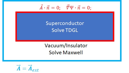
After reviewing some previously published TDGL simulations Gropp et al. (1996); Miyamoto and Hikihara (2004); Alstrøm et al. (2011), we noticed that usually Eq.(18) or Eq.(26) are enforced on the boundary of the superconductor. However this implies that the superconducting screening current has no effect on the magnetic field at the boundary and beyond the superconducting domain. This is physically incorrect for the situation of interest to us. The effect of screening currents is crucial when one is trying to simulate spatially nonuniform external magnetic field (like that arising from a nearby magnetic dipole), and the resulting nonlinear response of the superconductor.
To include the important physics of screening, our simulation is divided into two domains: Superconductor and Vacuum (Fig. 1). The full coupled TDGL equations are solved in the superconductor domain, while only Maxwell’s equations are solved in the vacuum domain, with appropriate boundary conditions at the interface. Any finite value of or would lead to a finite current passing through the superconductor-vacuum boundary (red box in Fig. 1), which is nonphysical, hence equations (24) and (25) are enforced at the superconductor/vacuum interface. Any externally applied magnetic field is introduced by placing a boundary condition on the outer boundary of vacuum domain (Eq.(26)). The vacuum domain is assumed to be large enough that at the external boundary (blue box in Fig. 1) the magnetic field generated by the superconductor is negligible. Fig. 1 schematically summarizes this scenario.
We now examine several key examples where it is crucial to include the screening response of the superconductor to capture the interesting physics. Through these two examples we validate our approach to solving the TDGL equations.
IV.2 Superconducting sphere in a uniform magnetic field
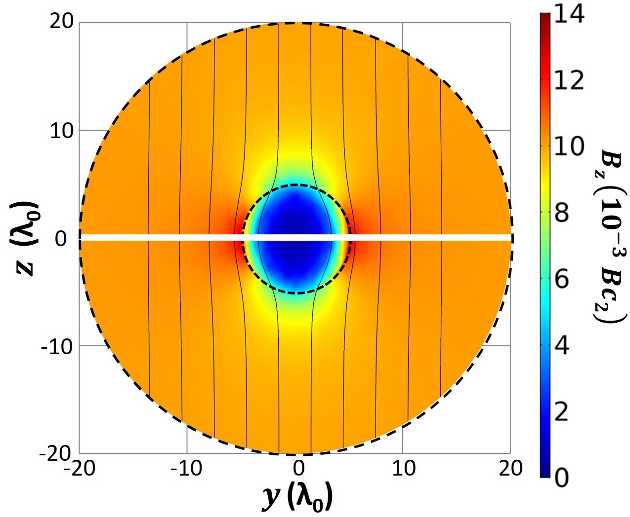
First consider the classic problem of a superconducting sphere immersed in a uniform magnetic field. Assume that the superconductor remains in the Meissener state. It is known from the exact solution to this problem that there will be an enhancement of the magnetic field at the equatorial surface of the superconducting sphere due the magnetic flux that is expelled from the interior of the sphere. To test this approach to solving the TDGL equations we created a model of this situation in COMSOL 333For all the simulations presented in this work, the time-dependent study in the COMSOL Multiphysics software was used. The Direct-MUMPS solver with the default parameters was used as the general solver and time-stepping was performed using the Backward Differentiation Formula (BDF) solver. The maximum time-step was constrained to 1. The free tetrahedral mesh was used on the domain, and the same mesh was mirrored in the domain.. We simulated the response using the two-domain method, and the conventional single domain method used in many other contexts, and then compared both results with the exact analytical solution for the magnetic field profile Matute (1999).
Fig. 2 shows the TDGL simulation of a superconducting sphere subjected to a uniform static external magnetic field. The boundaries of the spheres are shown with the dashed lines, where the smaller sphere is the superconducting sphere, and the larger sphere is the vacuum domain. The colors represent the amplitude of the -component of the applied magnetic field in the y-z plane passing through the common center of the spheres. Black lines show the streamline plot of magnetic field in the same y-z plane. The streamline plot is defined as collection of lines that are tangent everywhere to the instantaneous vector field, in this case to the direction of the magnetic field. The simulation was initialized in a field free configuration and the external magnetic field was applied at . The simulation was iterated for time steps after which the changes in were per iteration.
To test the reproducibility of the result, the simulation was later repeated, but this time the external magnetic field was increased linearly in time from zero to between time and . After this, the simulation was again iterated for time steps. The results of these two simulations were identical.
Eqs. (24) and (25) were enforced on the spherical superconductor-vacuum boundary () in both cases. When the two-domain method was used, the TDGL equations were solved in the inner sphere () and only Maxwell’s equations were solved in the vacuum domain ( ). Eq.(26) was enforced at the outer boundary of the simulation (). When the single domain simulation method was used, Eq.(26) was enforced at the inner boundary of the simulation () and the vacuum domain was not utilized.
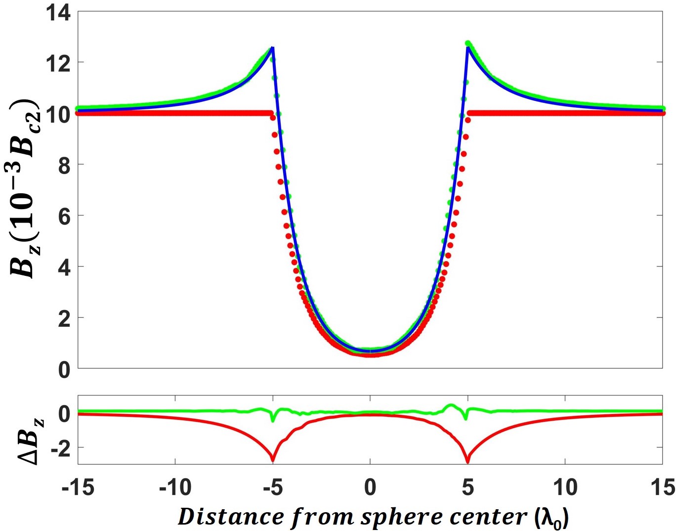
The top plot in Fig. 3 shows the profile of the z-component of magnetic field () along a line through the center of the sphere, in a plane perpendicular to the externally applied magnetic field (white line in Fig. 2) calculated from the single domain simulation, the two-domain simulation and the analytic result. Inside the sphere, the magnetic field profile calculated from the single domain simulation and the two-domain simulation are very similar although not identical. The bottom plot in Fig. 3 shows the difference between the TDGL simulation results and the analytic solution. The field deep inside the sphere is strongly suppressed by the screening currents. This can also be seen from the color-map in Fig. 2. The blue region inside the sphere corresponds to the fully shielded portion of the sphere. However, there is a region outside the sphere around the equator where the magnetic field is enhanced (red color in Fig. 2).
At the surface of the sphere the magnetic field calculated from the two-domain model reproduces the exact analytic solution, while the single domain model fails to account for the enhancement of magnetic field on the equator of the sphere. This disparity between the single domain model and analytic solution is caused by the treatment of the boundary conditions. In the single domain model, Eq. 26 is enforced at the superconductor-vacuum interface, which completely ignores the effect of screening currents. Thus a two-domain model should be used for any problem where screening and the magnetic field profile at the surface of the superconductor is important.
IV.3 Point magnetic dipole above a semi-infinite superconductor
To ensure that we can accurately simulate the screening currents produced by a spatially nonuniform magnetic field, we numerically simulated the case of a static point magnetic dipole placed at a height of above the surface of a semi-infinite superconductor. The superconducting domain and vacuum domain are simulated inside two coaxial cylinders with equal radius with common axis along the direction of the Cartesian coordinate system. The origin of this coordinate system is located on the superconductor surface immediately below the dipole. The thickness of the superconducting domain is and the height of the vacuum domain is . The normalized friction coefficient and the GL parameter are set to .
The surface magnetic fields produced by the dipole are assumed to be below the lower critical field , so that the superconductor remains in the Meissner state. The simulation was started with a superconductor in the uniform Meissner state and the dipole field equal to 0. Then, at time , the dipole magnetic field is turned on, and the simulation is iterated in time until the relative tolerance of is achieved for all the variables in the column vector of all unknowns (Eq. 19). At this point the static solution to the problem is obtained. Later the simulation was repeated with external magnetic field linearly increasing with time over time interval before reaching a set constant value. The results of these two simulations were identical.
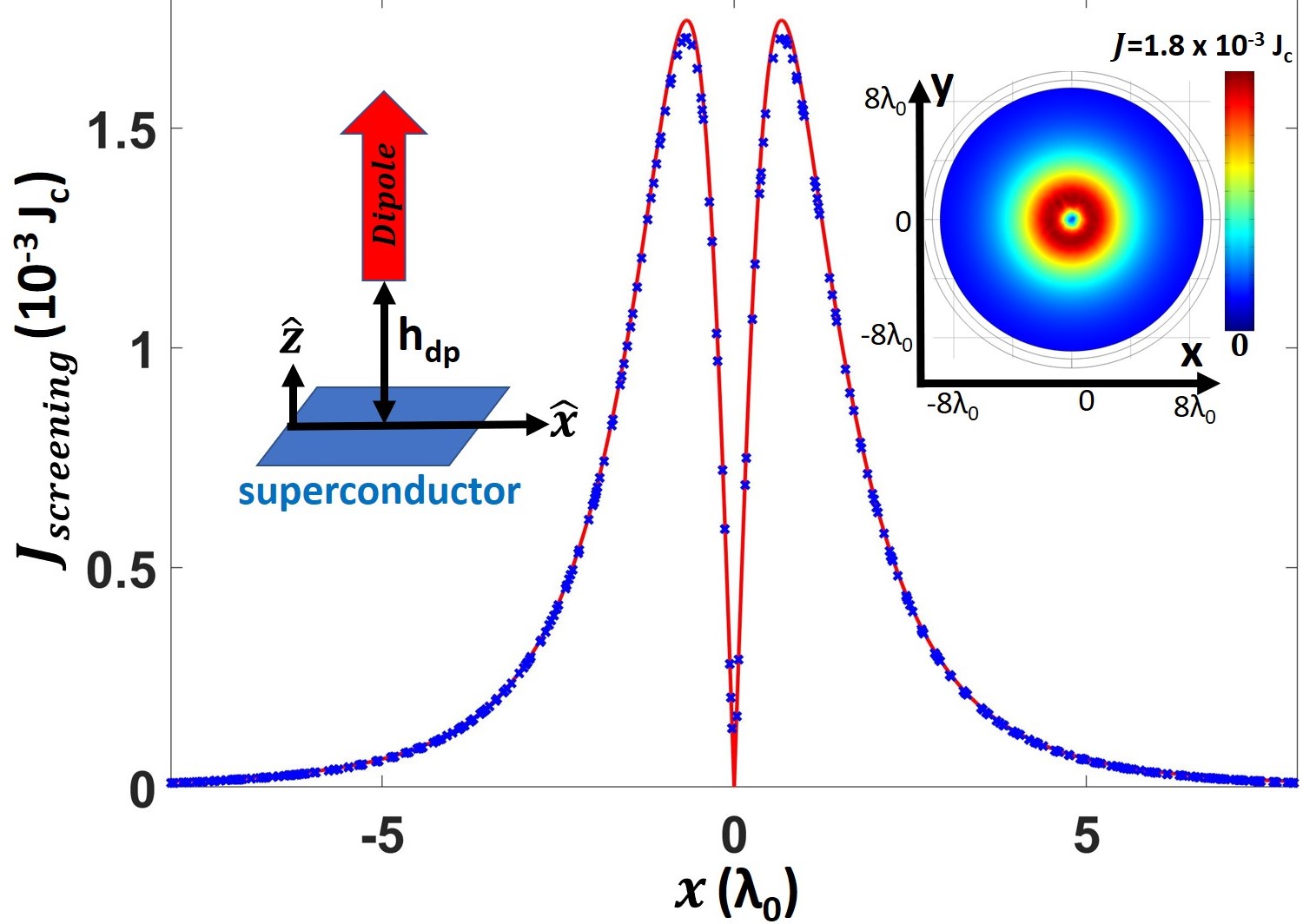
We compared our TDGL results for the distribution of the surface screening current density to numerical results obtained by Melnikov Mel’nikov et al. (1998) for the case of a perpendicular magnetic dipole. Fig. 4 shows a comparison of the calculated screening current profiles. Both results show that there is a circulating screening current centered directly below the dipole. Also note that the screening current reaches zero at the outer boundary of the simulation. This indicates that a sufficiently large domain was chosen for simulation and no finite size effects are expected. We have very good agreement between the two-domain TDGL simulation result and numerical results obtained by Melnikov, in the low magnetic field limit where there are no vortices (Fig. 4). This, and the previous result, serve to validate our two-domain approach to properly capturing the screening response of the superconductor in TDGL.
V Application: Nonlinear Near-Field Magnetic Microwave Microscopy of a Superconductor
The dominant material used in SRF cavities is Nb, which is a type II superconductor and can host vortices. Vortices can be created by high rf magnetic fields used in SRF cavity operation and point-like surface defects Ge et al. (2010); Iwashita et al. (2008). Vortices can also form due to flux trapped during the cool down procedure. Recent studies showed that the trapped magnetic flux amount depends on the rate at which the cavity is cooled down through the critical temperature and the level of the ambient magnetic field Romanenko et al. (2014a). Decreasing the trapped magnetic flux amount leads to better cavity performance.
The type of vortices inside an SRF cavity and the dynamics of those vortices was theoretically studied by Gurevich and Ciovati Gurevich and Ciovati (2008). For large parallel surface rf magnetic fields and a point-like surface defect, a vortex first enters the superconductor as a vortex semiloop. To study the dynamics of these vortex-semiloops a novel near-field magnetic microwave microscope was successfully built using a magnetic writer from a conventional magnetic recording hard-disk drive Lee et al. (2005); Mircea et al. (2009); Tai et al. (2011, 2013, 2014a, 2015); Oripov et al. (2019). A magnetic write head can produce rf magnetic field localized to a length scale Michael J. Conover, principal engineer at Seagate Technology . In the experiment, a Seagate perpendicular magnetic writer head is attached to a cryogenic XYZ positioner and used in a scanning probe fashion. Probe characterization results and other details can be found in Tai et al. (2011, 2013, 2014a, 2015); Oripov et al. (2019). The probe produces an rf magnetic field perpendicular to the sample surface. The sample is in the superconducting state, so to maintain the Meissner state a screening current is induced on the surface. This current generates a response magnetic field which is coupled back to the same probe, creates a propagating signal on the attached transmission line structure, and is measured with a spectrum analyzer at room temperature. Since superconductors are intrinsically nonlinear Xu et al. (1995), both linear and nonlinear responses to an applied rf magnetic field are expected. In said experiment, mainly the third-harmonic response to the inhomogeneous driving field is measured.
The rf magnetic field produced by the magnetic writer probe sitting on top of a sample is very similar to the magnetic field produced by a horizontal point magnetic dipole with normalized magnetic moment placed at a height above the sample. The normalized vector potential produced by such a dipole in free space is given by Chow (2006):
| (27) |
where the origin of the coordinate system is on the superconductor surface immediately below the dipole. While this is very different from a uniform and parallel magnetic field inside an actual SRF cavity, the dynamics of the vortex semiloops created by this field should be very similar.
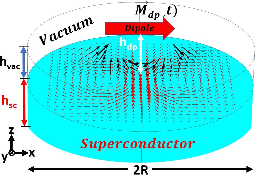
The superconducting domain and vacuum domain are simulated inside two coaxial cylinders with equal radius (see Fig. 5) with common axis along the direction of the Cartesian coordinate system. The thickness of the superconducting domain is and the height of the vacuum domain is in normalized units.
The boundary condition Eq. 26 is enforced at the top of the vacuum domain, whereas a boundary condition is enforced at the bottom and the sides of the superconducting domain, since it is expected that the superconducting currents due to the Meissner state will fully shield the externally applied magnetic field before it reaches the outer boundary of the superconductor.
The interaction between the probe and the sample was modeled by solving the TDGL equations. In the simulation, we specify indirectly through the the magnetic field experienced at the origin (on the superconductor surface immediately below the dipole) , where . The driving rf magnetic field profile is specified through the analytic equation for the magnetic vector potential of a point dipole (Eq. 27), therefore the dipole itself can be placed either inside the vacuum domain or beyond it without affecting the accuracy of the simulation. is chosen to be large enough to be consistent with Eq. 26 at the top of the vacuum domain.
The main objective of this work is to simulate the response of the SRF grade Nb, thus the parameters are chosen accordingly. For Nb, ranges from to depending on the RRR value of the material, and Liarte et al. (2017); Jana et al. (2018). The characteristic time for the relaxation of , for Nb bulk samples in the clean limit . Consequently, the 100-2000 range for the period of the magnetic dipole corresponds to a frequency range of . Hence, the period of the dipole rf magnetic field was chosen to be . The GL parameter Singer (2015), and is on the order of unity (Parameters summarize in Table.I). It should be noted that the relaxation time with is ”fast” in the sense that the order parameter will quickly follow any variations in rf field or current.
The spatial distribution of the magnetic field at the surface of the superconductor is set through the value for the dipole height . While the driving rf magnetic field is specified through the analytic equation Eq. 27, the goal is to reproduce the actual spatial distribution produced by the magnetic writer head at the surface of the superconductor, which was provided by the manufacturer Michael J. Conover, principal engineer at Seagate Technology . To produce similar spatial distribution of the magnetic field, we set the dipole height to the range which corresponds to of in normalized units.
V.1 The evolution of vortex semiloops with time
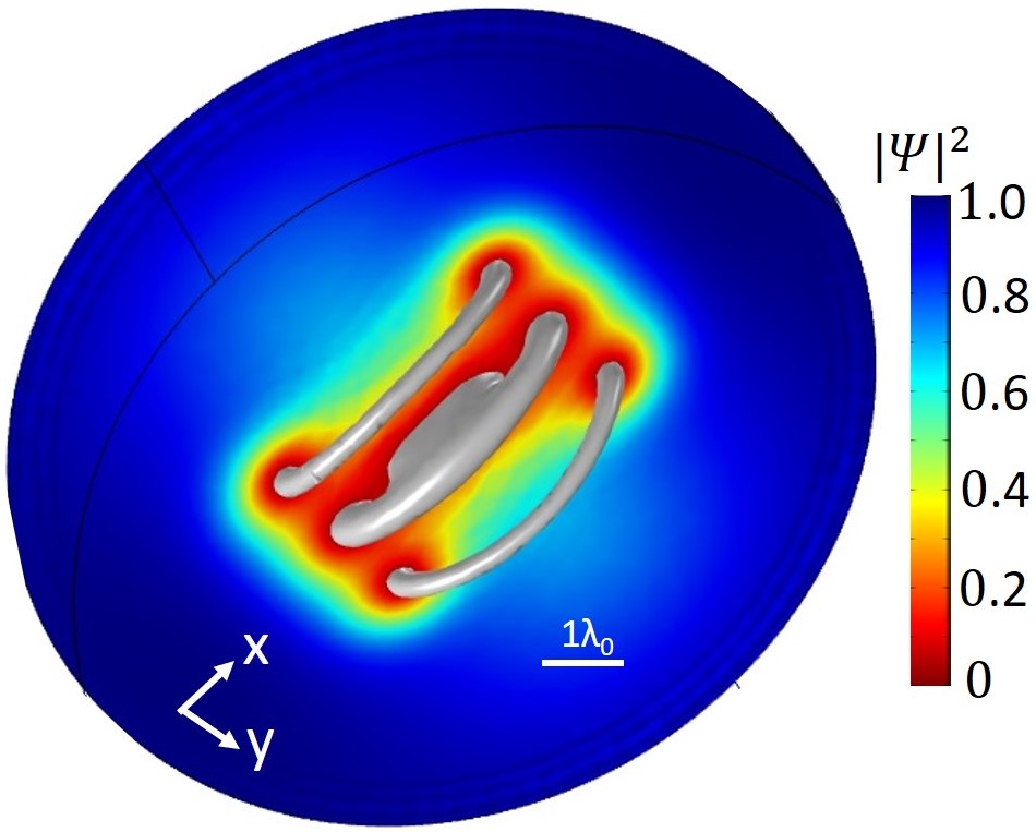
We consider a dipole that oscillates sinusoidally in time with frequency , and calculate the response of the superconductor to this external inhomogeneous and time-dependent magnetic field. Our objective is to describe a spatially-inhomogenious microwave frequency stimulus of the superconducting surface. In this section a uniform superconductor domain with no defects is considered. The simulation is started with the order parameter having a uniform value of everywhere. At time the externally applied magnetic field is turned on. Then the simulation is run for several rf cycles to reach the steady state solution.
Fig. 6 shows the results for such a simulation, and the parameters are given in Table I . The simulation was run for 3 driving periods to stabilize and the results shown in Fig. 6 are from the driving period. Three well-defined vortex semiloops are illustrated by the three-dimensional silver surface corresponding to .
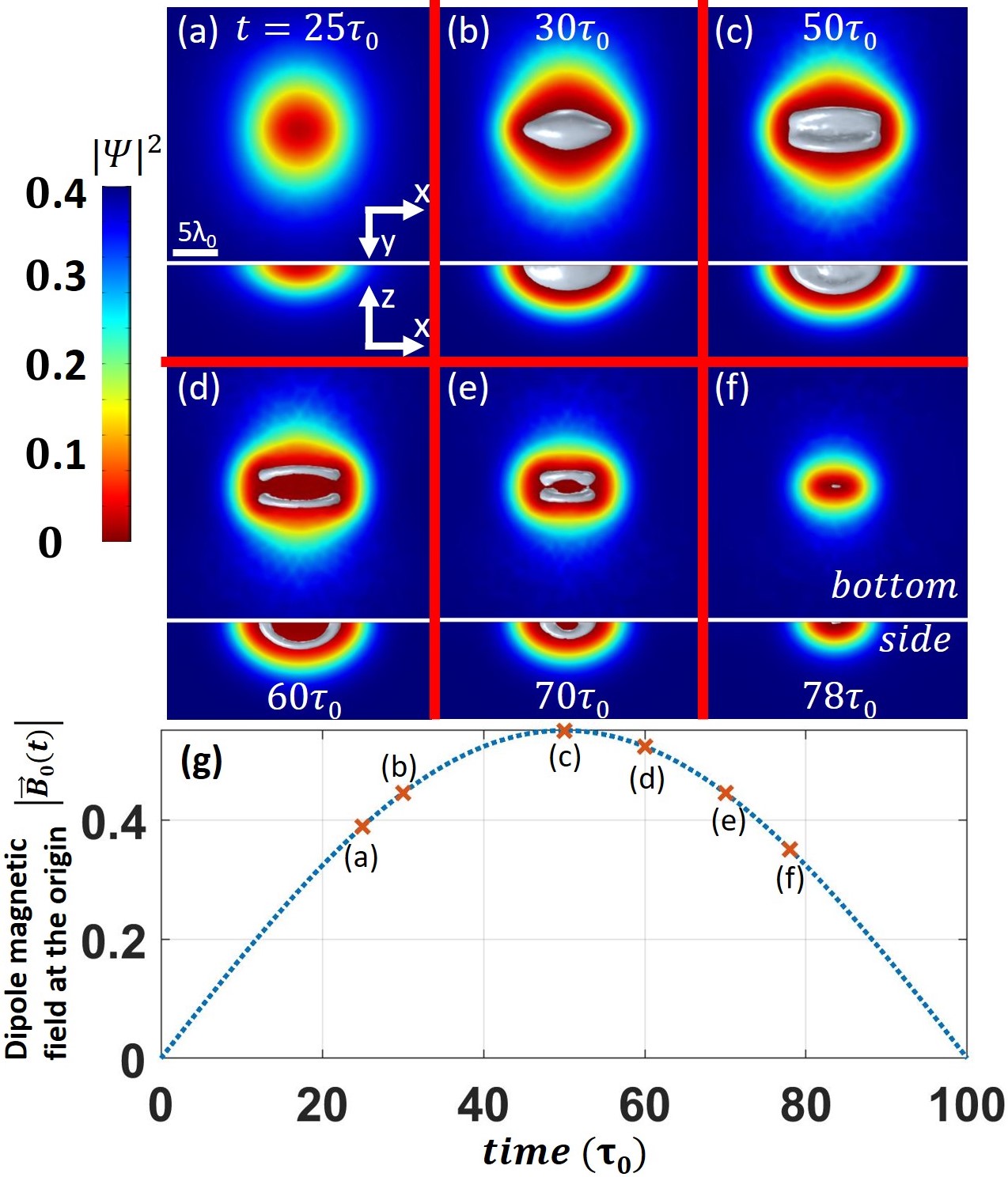
Fig. 7 shows results for a similar simulation, illustrating the order parameter space and time dependence, and the parameters are given in Table I. The simulation was run for 5 driving periods to stabilize, and the results shown in Fig. 7 are from the driving period. We see that as increases a suppressed domain (red region) forms at the superconductor surface immediately below the dipole. At the magnetic field reaches its peak value and the suppressed superconducting region reaches its deepest point inside the superconducting domain illustrated by the silver surface in Fig. 7(c). Later (), the amplitude of the external driving magnetic field decreases, the suppressed domain rapidly diminishes and vortex semiloops spontaneously emerge, become well-defined (Fig. 7.d,e), then move back towards the surface and vanish there before the end of the first half of the rf cycle. In the second part of the rf cycle, the same process is repeated but now antivortex-semiloops enter the superconducting domain. The full solution animated over time is available online Vor (a). In this particular scenario vortices and anti-vortices never meet, unlike the situation discussed in Tai (2013).
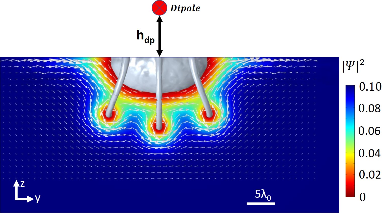
Fig. 8 shows another simulation result with a different set of parameters (listed in Table I). Here the dipole is further away from the surface, at and the temperature is set to . Three dimensional silver contour surfaces correspond to . The two-dimensional screening currents (white arrows) and two-dimensional order parameter (colors) are plotted in the yz-plane. Three vortex semiloops are clearly visible in this cross-section cut. We see that the vortex semiloops penetrated somewhat deeper into the superconductor than the suppressed order parameter domain.
V.2 The evolution of vortex semiloops with rf field amplitude
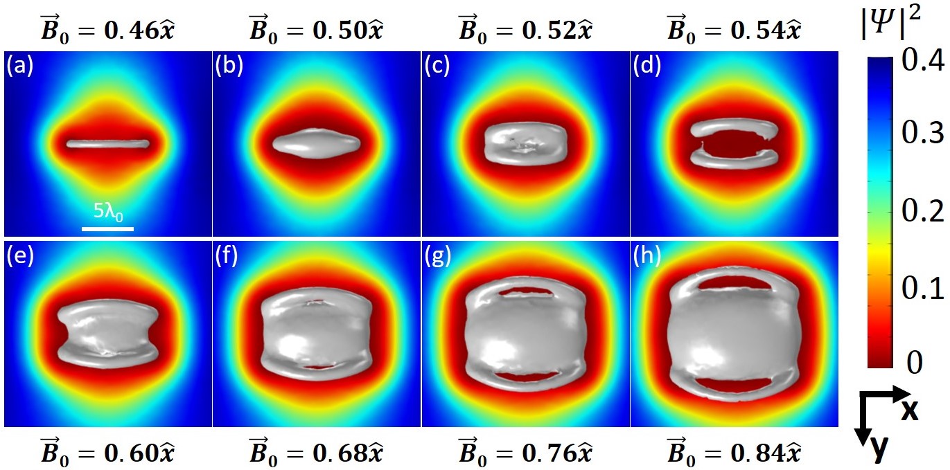
One can also study the effect of the applied rf field amplitude, defined through , on the number and the dynamics of vortex semiloops. Fig. 9 shows the bottom view of the order parameter on the surface of the superconducting domain for different values of the applied rf magnetic field amplitude, all at the same point in the rf cycle ( and at its peak value). As expected, the number of vortex semiloops increase with increasing . Once is reached, a normal state domain emerges at the origin, as opposed to a suppressed domain observed at lower rf field amplitudes. The full solution as a function of peak applied magnetic field amplitude is available online Vor (b).
V.3 The effect of localized defects on rf vortex semiloops
In the past GL has been used to estimate the surface superheating field of superconductors Transtrum et al. (2011) and TDGL was used to study RF vortex nucleation in mesoscopic superconductors Hernández and Domínguez (2008). Here we wish to examine the effect of a single point-like defect on rf vortex nucleation in a bulk sample.
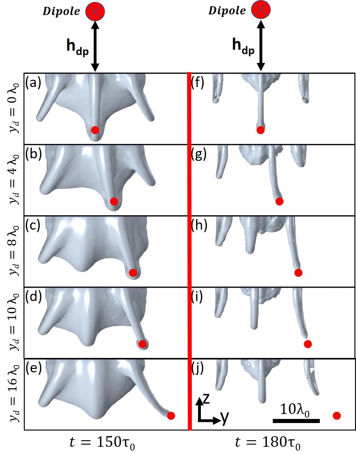
The effect of a localized defect can be specified through the function in Eqs. (11) and (23), which can range from (strong suppression of superconductivity) to (fully superconducting). Here, dictates the maximum possible value for the superfluid density in the absence of external magnetic field. A simple defect can be created, for example by defining a Gaussian-in-space domain with suppressed superconducting critical temperature , where :
| (28) |
where are the central coordinates of the defect and are the standard deviations in the 3 coordinate directions, all expressed in normalized values. Fig. 10 shows a simulation which was done with parameters given in Table I . A localized defect with and is located at , where is varied from 0 to , to represent a localized defect that is centered 12 penetration depths () below the surface and offset various distances from the oscillating dipole. We observed very similar vortex semiloops in the time domain evolution as those shown above. However, one of the vortex semiloops is now attracted towards the defect location (shown as red dot in Fig.10) and is distorted in shape. Furthermore, the vortex attracted by the defect remains inside the superconductor longer compared to the other vortex semiloops. Note that the semiloop disappears at the end of each half of the rf cycle, hence the pinning potential of this defect is not strong enough to trap the vortex semiloop, only to modify the rf behaviour.
V.4 Surface Defect in a Parallel rf magnetic field
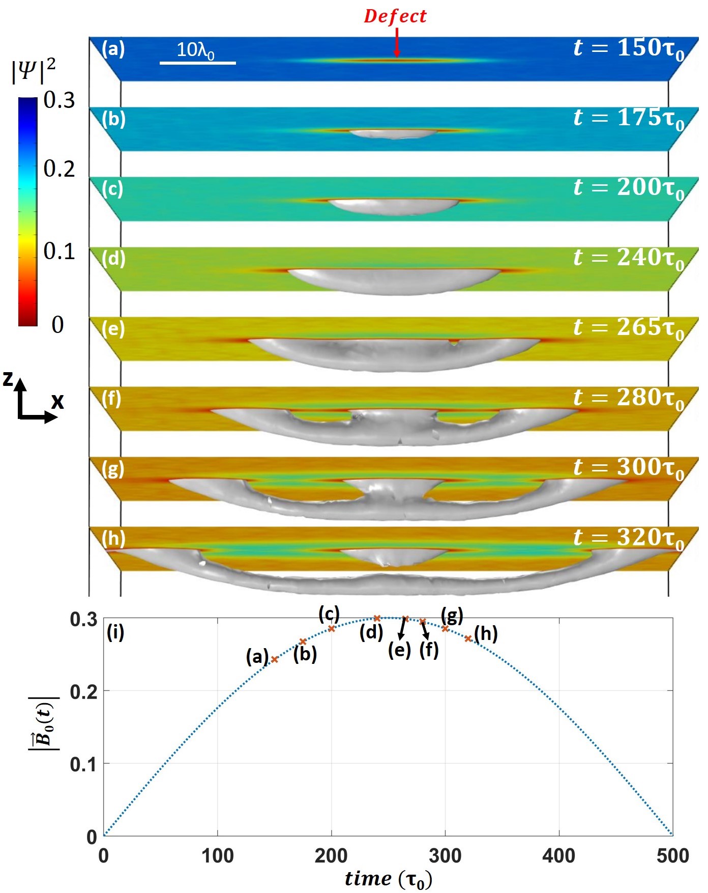
In previous sections, we examined the dynamics of vortex semiloops created by a point magnetic dipole, as it is relevant to the magnetic microscopy experiment Oripov et al. (2019). In this section we will briefly address the more general case which is appropriate for SRF applications, a uniform parallel rf magnetic field above the superconductor in the presence of a single defect on the surface. In order to have truly uniform field, the boundary between superconductor and vacuum should be simulated as an infinite plane. To accurately simulate the screening currents on the surface of the cavity, the two-domain simulation method described in section IV.1 is used. The superconducting domain and vacuum domain are simulated inside 2 rectangular blocks instead of the cylindrical domain used in previous sections. The block dimensions are (along the field direction) and width . The height of superconducting domain is , and the height of the vacuum domain is . The vacuum domain is placed on the top of the superconducting domain. To mimic the infinite domain periodic boundary conditions are applied in the and directions both for and .
Fig. 11 shows the solution for the order parameter in the case of externally applied rf magnetic field parallel to the surface of the superconductor along the axis direction. A localized defect (modeled with Eq. 28) is placed at the origin () with and and . A transient solution starting from the zero field Meissner state is studied in this case. A vortex semiloop penetrates into the superconducting domain at the site of the defect as the rf field amplitude increases Gurevich (2015). We consider vortex semiloops as a unique type of vortex, distinctly different from parallel line vortices Antoine et al. (2019). When the amplitude of magnetic field is increased beyond that used in Fig.(11), we observe that arrays of parallel line vortices nucleate into the superconductor. While no defect was required to create vortex semiloops with the magnetic dipole source, a surface defect is required to create such a vortex when parallel field is applied.
The solution shown in Fig. 11 is an initial transient solution, i.e. the simulation is not run for several cycles to reach the steady state condition. When the vortex semiloop reaches the boundary of the simulation in the field direction the results become nonphysical due to artificial pinning of the vortex semiloop by the boundaries. This finite size effect is currently limiting our ability to perform full rf parallel field simulation. Nevertheless, the transient solution shown in Fig. 11 may give some insight into the development of vortex semiloops in SRF cavities Gurevich and Ciovati (2008), and will be pursued in future work.
VI Discussion
These simulations have proven very useful in understanding the measured third-harmonic response of Nb materials, subjected to intense localized rf magnetic fields Oripov et al. (2019). In all the cases described in the previous section, the order parameter and the vector potential are first retrieved from the simulation. Using eq.(13) the screening super-current is calculated for each point in space and time. The response magnetic field generated by said currents at the location of the dipole is calculated using the Biot-Savart law. The third-harmonic response recovered at the location of the dipole is obtained through Fourier transformation of the calculated response magnetic field. Later the TDGL-derived third-harmonic voltage was compared with the third-harmonic response measured from experiment. The comparison is discussed in detail in Ref. Oripov et al. (2019).
While most of the work was done for an oscillating parallel magnetic dipole, we also showed that vortex semiloops are created when a localized defect is introduced in the internal surface of an SRF cavity. It is plausible that vortex semiloops are one of the key sources of dissipation inside an SRF cavity at high operating power. The losses associated with such a vortex can be studied by combining the TDGL numerical technique with the experimental work published in Oripov et al. (2019).
While recent advances in SRF cavity fabrication, especially the novel technique of Nitrogen doping and Nitrogen infusion Grassellino et al. (2013); Martinello et al. (2016); Ngampruetikorn and Sauls (2019), have significantly improved the properties of SRF cavities, the microscopic mechanism responsible for this improvement is yet unknown. Nitrogen infused cavity surfaces can perhaps be thought of as a layered superconductor, with a dirty superconductor on top acting like a ”slow” superconductor and suppressing vortex nucleation Liarte et al. (2017); Romanenko et al. (2014b); Romanenko (2018). The characteristic time scale governing the dynamic behaviour of the superconductor was calculated by Gor’kov and Eliashberg to be Gor’kov and Eliashberg (1968). Superconductors in the dirty limit, with a finite inelastic electron-phonon scattering time subject to can be better studied using gTDGL, where the effect of a finite inelastic electron scattering time is considered Kramer and Watts-Tobin (1978). However, Tinkham has argued that the characteristic time for the relaxation of the order parameter in a gapped superconductor in the clean limit should be much longer than the characteristic GL time , instead on the order of Schmid (1968); Tinkham (2004); Kopnin (2001) (s for Nb Kaplan et al. (1976)). It has been argued that a TDGL-like equation that incorporates these long relaxation times, a so called slow-GL model, can be used in such circumstances (Tinkham, 2004). Perhaps the effects of Nitrogen doping and Nitrogen infusion on Nb cavities can be better understood by considering the effects of this different time scale on vortex semiloop formation. This can be accomplished with a sequence of TDGL, gTDGL and slow-GL model simulations.
There is also a proposal to create superconductor-insulator multilayer thin-film coatings with enhanced rf critical fields Gurevich (2006). TDGL simulations can be used to guide the design process for these multilayers. Although TDGL is not a microscopic theory, and it is sometimes difficult to link the parameters of the model to observable experimental quantities, the general behaviour of the superconductor response to microwave magnetic fields, and the development of vortex semiloops, is still very insightful.
| Parameter Name |
Symbol |
Scale |
Fig. 4 |
Fig. 6 |
Fig. 7 |
Fig. 8 |
Fig. 9 |
Fig. 10 |
Fig. 11 |
|---|---|---|---|---|---|---|---|---|---|
| Temperature | 0 | 0 | 0.6 | 0.9 | 0.6 | 0.85 | 0.7 | ||
| Applied RF field amplitude | 0.01 | 0.75 | 0.55 | 0.3 | 0.46-0.84 | 0.3 | 0.3 | ||
| 0.009 | 0.69 | 0.49 | 0.268 | 0.41-0.75 | 0.268 | 0.268 | |||
| Period of Applied RF field | Static | 200 | 200 | 200 | 200 | 200 | 1000 | ||
| Dipole height | 1 | 8 | 8 | 12 | 8 | 12 | - | ||
| Radius of the simulation domain | 8 | 12 | 35 | 60 | 20 | 40 | 80x60 | ||
| Height of superconducting domain | 10 | 6 | 20 | 50 | 8 | 25 | 20 | ||
| Height of vacuum domain | 5 | 3 | 20 | 25 | 4 | 15 | 10 | ||
| Ginzburg-Landau parameter | - | 1 | 1 | 1 | 1 | 1 | 1 | 1 | |
| Ratio of characteristic time scales | - | 1 | 1.675 | 1 | 0.2 | 1 | 0.5 | 1 |
VII Conclusion
In this work we present a novel way to perform TDGL simulations in 3D for spatially nonuniform magnetic fields applied to a superconducting surface. Proof of principle results are presented to show the validity of the proposed two-domain simulation method. The vortex semiloops created by a point magnetic dipole above the surface, and the rf dynamics of such vortices are studied. The effect of temperature, rf field amplitude and the surface defects on the vortex semiloops are studied and presented. The resulting third-harmonic nonlinear response can be calculated and compared with the experimental data (comparison published in Oripov et al. (2019)). Finally, we demonstrate the creation of such rf vortex semiloops in the case of a uniform rf magnetic field parallel to a superconducting surface with a single defect.
Acknowledgments
Acknowledgements.
This research was conducted with support from U.S. Department of Energy/ High Energy Physics through Grant No.DESC0017931.References
- Seidel (2015) Paul Seidel, ed., Applied Superconductivity: Handbook on Devices and Applications, Vol. 2 (WILEY-VCH Verlag GmbH Co. KGaA, 2015).
- (2) “Technological applications of superconductivity. (n.d.) McGraw-Hill Concise Encyclopedia of Physics. (2002),” https://encyclopedia2.thefreedictionary.com/Technological+applications+of+superconductivity, accessed: 2019-08-10.
- Aune et al. (2000) B. Aune, R. Bandelmann, D. Bloess, B. Bonin, A. Bosotti, M. Champion, C. Crawford, G. Deppe, B. Dwersteg, D. A. Edwards, H. T. Edwards, M. Ferrario, M. Fouaidy, P.-D. Gall, A. Gamp, A. Gössel, J. Graber, D. Hubert, M. Hüning, M. Juillard, T. Junquera, H. Kaiser, G. Kreps, M. Kuchnir, R. Lange, M. Leenen, M. Liepe, L. Lilje, A. Matheisen, W.-D. Möller, A. Mosnier, H. Padamsee, C. Pagani, M. Pekeler, H.-B. Peters, O. Peters, D. Proch, K. Rehlich, D. Reschke, H. Safa, T. Schilcher, P. Schmüser, J. Sekutowicz, S. Simrock, W. Singer, M. Tigner, D. Trines, K. Twarowski, G. Weichert, J. Weisend, J. Wojtkiewicz, S. Wolff, and K. Zapfe, “Superconducting TESLA cavities,” Physical Review Special Topics - Accelerators and Beams 3, 092001 (2000).
- Padamsee et al. (2008) Hasan Padamsee, Jens Knobloch, and Tomas Hays, RF Superconductivity for Accelerators, 2nd ed. (WILEY-VCH Verlag GmbH Co. KGaA, Mörlenbach, Germany, 2008).
- Singer (2015) W Singer, “SRF Cavity Fabrication and Materials,” CERN Yellow Report CERN-2014-005 , 171–207 (2015), arXiv:1501.07142 .
- Martinello et al. (2015) Martina Martinello, Mattia Checchin, Anna Grassellino, Oleksandr Melnychuk, Sam Posen, Alexander Romanenko, Dmitri Sergatskov, and John F. Zasadzinski, “Trapped Flux Surface Resistance Analysis for Different Surface Treatments,” in Proceedings, 17th International Conference on RF Superconductivity (SRF2015) (Whistler, 2015) p. MOPB015.
- Ge et al. (2010) M. Ge, G. Wu, D. Burk, J. Ozelis, E. Harms, D. Sergatskov, D. Hicks, and L. D. Cooley, “Routine characterization of 3D profiles of SRF cavity defects using replica techniques,” Superconductor Science and Technology 24, 35002 (2010).
- Iwashita et al. (2008) Yoshihisa Iwashita, Yujiro Tajima, and Hitoshi Hayano, “Development of high resolution camera for observations of superconducting cavities,” Phys. Rev. ST Accel. Beams 11, 93501 (2008).
- Gurevich and Ciovati (2008) Alexander Gurevich and Gianluigi Ciovati, “Dynamics of vortex penetration, jumpwise instabilities, and nonlinear surface resistance of type-II superconductors in strong RF fields,” Phys. Rev. B 77, 104501 (2008).
- Lee et al. (2005) Sheng-Chiang Lee, Su-Young Lee, and Steven M. Anlage, “Microwave nonlinearities of an isolated long bicrystal grain boundary,” Phys. Rev. B 72, 24527 (2005).
- Mircea et al. (2009) Dragos I. Mircea, Hua Xu, and Steven M. Anlage, “Phase-sensitive harmonic measurements of microwave nonlinearities in cuprate thin films,” Phys. Rev. B 80, 144505 (2009).
- Tai et al. (2011) Tamin Tai, X X Xi, C. G. Zhuang, Dragos I. Mircea, and Steven M. Anlage, “Nonlinear Near-Field Microwave Microscope for RF Defect Localization in Superconductors,” IEEE Transactions on Applied Superconductivity 21, 2615–2618 (2011).
- Tai et al. (2013) Tamin Tai, Behnood G. Ghamsari, and Steven M. Anlage, “Nanoscale Electrodynamic Response of Nb Superconductors,” IEEE Transactions on Applied Superconductivity 23, 7100104 (2013).
- Tai et al. (2014a) Tamin Tai, Behnood G. Ghamsari, Thomas R. Bieler, Teng Tan, X X Xi, and Steven M. Anlage, “Near-field microwave magnetic nanoscopy of superconducting radio frequency cavity materials,” Applied Physics Letters 104, 232603 (2014a).
- Tai et al. (2015) Tamin Tai, Behnood G. Ghamsari, Thomas R. Bieler, and Steven M. Anlage, “Nanoscale nonlinear radio frequency properties of bulk Nb: Origins of extrinsic nonlinear effects,” Phys. Rev. B 92, 134513 (2015).
- Oripov et al. (2019) Bakhrom Oripov, Thomas R. Bieler, Gianluigi Ciovati, Sergio Calatroni, Pashupati Dhakal, T. Junginger, Oleg B. Malyshev, G. Terenziani, Anne-Marie Valente-Feliciano, Reza Valizadeh, S. Wilde, and Steven M. Anlage, “High-Frequency Nonlinear Response of Superconducting Cavity-Grade Surfaces,” Physical Review Applied 11, 64030 (2019).
- Tai et al. (2014b) Tamin Tai, B G Ghamsari, and Steven M Anlage, “Modeling the nanoscale linear response of superconducting thin films measured by a scanning probe microwave microscope,” J. Appl. Phys 115, 203908 (2014b).
- Landau and Ginzburg (1950) Lev Davidovich Landau and Vitaly Lazarevich Ginzburg, “On the Theory of Superconductivity,” J. Exptl. Theoret. Phys. (U.S.S.R.) 20, 1064–1082 (1950).
- Ginzburg and Landau (2009) Vitaly Lazarevich Ginzburg and Lev Davidovich Landau, “On the Theory of Superconductivity,” in On Superconductivity and Superfluidity: A Scientific Autobiography (Springer Berlin Heidelberg, Berlin, Heidelberg, 2009) pp. 113–137.
- Cyrot (1973) M Cyrot, “Ginzburg-Landau theory for superconductors,” Reports on Progress in Physics 36, 103–158 (1973).
- Tinkham (2004) Michael Tinkham, Introduction to superconductivity, 2nd ed. (Dover Publications, Inc., Mineola, New York, 2004).
- Bogoliubov (1958a) Nikolay Nikolayevich Bogoliubov, “A new method in the Theory of Superconductivity-1,” Journal of Experimental and Theoretical Physics 7, 41 (1958a).
- Bogoliubov (1958b) Nikolay Nikolayevich Bogoliubov, “A new method in the Theory of Superconductivity–3,” Journal of Experimental and Theoretical Physics 7, 51 (1958b).
- Gennes (1964) P. G. De Gennes, “Boundary Effects in Superconductors,” Rev. Mod. Phys. 36, 225–237 (1964).
- Gennes (1999) P. G. De Gennes, Superconductivity of Metals and Alloys (Perseus Books Group,, Boulder, Colorado, 1999).
- Abrikosov et al. (1975) Alexei Alexeyevich Abrikosov, Lev Petrovich Gor’kov, and I. E. Dzyaloshinski, Methods of Quantum Field Theory in Statistical Physics, 2nd ed., edited by Richard A. Silverman, Dover Books on Physics (Dover Publications, 1975).
- Kopnin (2001) Nikolai B. Kopnin, Theory of Nonequilibrium Superconductivity (International Series of Monographs on Physics) (Oxford University Press, USA, 2001).
- Gor’kov (1958) Lev Petrovich Gor’kov, “On the energy spectrum of Superconductors,” J. Exptl. Theoret. Phys. (U.S.S.R.) 34(7), 735–739 (1958).
- Eilenberger (1968) Gert Eilenberger, “Transformation of Gorkov’s Equation for Type II Superconductors into Transport-Like Equations,” Zeitschrift for Physik 214, 195–213 (1968).
- Ehrenreich et al. (1983) Henry Ehrenreich, Frederick Seitz, and David Turnbull, Solid State Physics, 1st ed., Advances in Research and Applications, Vol. 37 (Academic Press, 1983).
- Usadel (1970) Klaus D. Usadel, “Generalized Diffusion Equation for Superconducting Alloys,” Phys. Rev. Lett. 25, 507–509 (1970).
- Flokstra (2010) Machiel Geert Flokstra, Proximity effects in superconducting spin-valve structures, Ph.D. thesis, Leiden University (2010).
- Schmid (1966) Albert Schmid, “A time dependent Ginzburg-Landau equation and its application to the problem of resistivity in the mixed state,” Physik der kondensierten Materie 5, 302–317 (1966).
- Gor’kov and Eliashberg (1968) Lev Petrovich Gor’kov and G M Eliashberg, “Generalization of the Ginzburg-Landau equations for non-stationary problems in the case of alloys with paramagnetic impurities,” Soviet Physics JETP 27, 328–334 (1968).
- Gurevich and Kubo (2017) Alexander Gurevich and Takayuki Kubo, “Surface impedance and optimum surface resistance of a superconductor with an imperfect surface,” Phys. Rev. B 96, 184515 (2017).
- Kubo and Gurevich (2019) Takayuki Kubo and Alexander Gurevich, “Field-dependent nonlinear surface resistance and its optimization by surface nanostructuring in superconductors,” Phys. Rev. B 100, 064522 (2019).
- Dynes et al. (1978) R. C. Dynes, V. Narayanamurti, and J. P. Garno, “Direct Measurement of Quasiparticle-Lifetime Broadening in a Strong-Coupled Superconductor,” Phys. Rev. Lett. 41, 1509–1512 (1978).
- Dynes et al. (1984) R. C. Dynes, J. P. Garno, G. B. Hertel, and T. P. Orlando, “Tunneling Study of Superconductivity near the Metal-Insulator Transition,” Phys. Rev. Lett. 53, 2437–2440 (1984).
- Zasadzinski (2003) John F. Zasadzinski, “Tunneling spectroscopy of conventional and unconventional superconductors,” in The Physics of Superconductors, Vol. 1, edited by K H Bennemann and J B Ketterson (Springer, Berlin, 2003) Chap. 8, p. 591.
- Balatsky et al. (2006) A. V. Balatsky, I. Vekhter, and Jian-Xin Zhu, “Impurity-induced states in conventional and unconventional superconductors,” Rev. Mod. Phys. 78, 373–433 (2006).
- Proslier et al. (2008) T. Proslier, John F. Zasadzinski, L. D. Cooley, Claire Z. Antoine, J. Moore, J. Norem, M. Pellin, and K. E. Gray, “Tunneling study of cavity grade Nb: Possible magnetic scattering at the surface,” Applied Physics Letters 92, 212505 (2008).
- Kramer and Watts-Tobin (1978) Lorenz Kramer and H. J. Watts-Tobin, “Theory of Dissipative Current-Carrying States in Superconducting Filaments,” Phys. Rev. Lett. 40, 1041–1043 (1978).
- Vodolazov et al. (2005) D. Y. Vodolazov, F. M. Peeters, M. Morelle, and Victor V. Moshchalkov, “Masking effect of heat dissipation on the current-voltage characteristics of a mesoscopic superconducting sample with leads,” Phys. Rev. B 71, 184502 (2005).
- Blatter et al. (1994) G. Blatter, M. V. Feigel’man, V. B. Geshkenbein, A. I. Larkin, and Valerii M. Vinokur, “Vortices in high-temperature superconductors,” Rev. Mod. Phys. 66, 1125–1388 (1994).
- Aranson and Kramer (2002) Igor S. Aranson and Lorenz Kramer, “The world of the complex Ginzburg-Landau equation,” Rev. Mod. Phys. 74, 99–143 (2002).
- Machida and Kaburaki (1993) Masahiko Machida and Hideo Kaburaki, “Direct simulation of the Time-Dependent Ginzburg-Landau equation for type-II superconducting thin film: Vortex dynamics and V-I characteristics,” Phys. Rev. Lett. 71, 3206–3209 (1993).
- Gropp et al. (1996) William D Gropp, Hans G Kaper, Gary K Leaf, David M Levine, Mario Palumbo, and Valerii M. Vinokur, “Numerical Simulation of Vortex Dynamics in Type-II Superconductors,” Journal of Computational Physics 123, 254–266 (1996).
- Hernández and Domínguez (2008) Alexander D. Hernández and Daniel Domínguez, “Dissipation spots generated by vortex nucleation points in mesoscopic superconductors driven by microwave magnetic fields,” Phys. Rev. B 77, 224505 (2008).
- Berdiyorov et al. (2013) G. R. Berdiyorov, M. M. Doria, A. R. De, C. Romaguera, M. V. Milošević, E. H. Brandt, and F. M. Peeters, “Current-induced cutting and recombination of magnetic superconducting vortex loops in mesoscopic superconductor-ferromagnet heterostructures,” Phys. Rev. B 87, 184508 (2013).
- Robson et al. (2017) Charles W Robson, Kieran A Fraser, and Fabio Biancalana, “Giant ultrafast Kerr effect in superconductors,” Phys. Rev. B 95, 214504 (2017).
- Sardella et al. (2006) Edson Sardella, André Luiz Malvezzi, Paulo Noronha Lisboa-Filho, and Wilson Aires Ortiz, “Temperature-dependent vortex motion in a square mesoscopic superconducting cylinder: Ginzburg-Landau calculations,” Phys. Rev. B 74, 14512 (2006).
- Alstrøm et al. (2011) Tommy Sonne Alstrøm, Mads Peter Sørensen, Niels Falsig Pedersen, and Søren Madsen, “Magnetic Flux Lines in Complex Geometry Type-II Superconductors Studied by the Time Dependent Ginzburg-Landau Equation,” Acta Applicandae Mathematicae 115, 63–74 (2011).
- Rogalla (2011) Horst Rogalla, 100 years of superconductivity (Taylor Francis, 2011).
- Hernández and Domínguez (2002) Alexander D. Hernández and Daniel Domínguez, “Surface barrier in mesoscopic type-I and type-II superconductors,” Phys. Rev. B 65, 144529 (2002).
- Aranson et al. (2001) Igor S. Aranson, Nikolai B. Kopnin, and Valerii M. Vinokur, “Dynamics of vortex nucleation by rapid thermal quench,” Phys. Rev. B 63, 184501 (2001).
- Bardeen et al. (1957a) John Bardeen, L. N. Cooper, and J. R. Schrieffer, “Microscopic Theory of Superconductivity,” Phys. Rev. 106, 162–164 (1957a).
- Bardeen et al. (1957b) John Bardeen, L. N. Cooper, and J R Schrieffer, “Theory of Superconductivity,” Phys. Rev. 108, 1175–1204 (1957b).
- Note (1) Note that the zero temperature GL coherence length can also be used as a normalization length scale (See Ref. Gropp et al. (1996); Peng and Cai (2017)).
- Note (2) This time scale is also used in Refs. Gropp et al. (1996); Hernández and Domínguez (2002); Hernández et al. (2007); Alstrøm et al. (2011); Blair and Hampshire (2018).
- Blair and Hampshire (2018) Alexander I. Blair and Damian P. Hampshire, “Time-Dependent Ginzburg-Landau Simulations of the Critical Current in Superconducting Films and Junctions in Magnetic Fields,” IEEE Transactions on Applied Superconductivity 28, 1–5 (2018).
- Gurevich (2017) Alexander Gurevich, “Theory of RF superconductivity for resonant cavities,” Superconductor Science and Technology 30, 034004 (2017).
- Sadovskyy et al. (2015) I A Sadovskyy, A E Koshelev, C L Phillips, D A Karpeyev, and A Glatz, “Stable large–scale solver for Ginzburg–Landau equations for superconductors,” Journal of Computational Physics 294, 639–654 (2015).
- Geurts et al. (2009) R. Geurts, M. V. Milošević, and F. M. Peeters, “Second generation of vortex-antivortex states in mesoscopic superconductors: Stabilization by artificial pinning,” Phys. Rev. B 79, 174508 (2009).
- Miyamoto and Hikihara (2004) Shuichi Miyamoto and Takashi Hikihara, “Dynamical behavior of fluxoid and arrangement of pinning center in superconductor based on TDGL equation,” Physica C: Superconductivity and its Applications 417, 7–16 (2004).
- Aftalion et al. (2001) Amandine Aftalion, Etienne Sandier, and Sylvia Serfaty, “Pinning phenomena in the Ginzburg-Landau model of superconductivity,” Journal des Mathematiques Pures et Appliquees 80, 339–372 (2001).
- (66) “COMSOL multiphysics modeling software,” https://www.comsol.com.
- Peng and Cai (2017) Lin Peng and Chuanbing Cai, “Finite Element Treatment of Vortex States in 3D Cubic Superconductors in a Tilted Magnetic Field,” Journal of Low Temperature Physics 188, 39–48 (2017).
- Salvi et al. (2010) D. Salvi, Dorin Boldor, J. Ortego, G. M. Aita, and C. M. Sabliov, “Numerical modeling of continuous flow microwave heating: A critical Comparison of COMSOL and ANSYS,” Journal of Microwave Power and Electromagnetic Energy 44, 187–197 (2010).
- Gomes (2008) G Gomes, “Comparison between COMSOL and RFSP-IST for a 2-D Benchmark Problem,” in Proceedings, COMSOL Conference (Hannover 2008): (2008).
- Cardiff and Kitanidis (2008) Michael Cardiff and Peter K. Kitanidis, “Efficient solution of nonlinear, underdetermined inverse problems with a generalized PDE model,” Computers and Geosciences 34, 1480–1491 (2008).
- Du (1994) Q. Du, “Finite element methods for the time-dependent Ginzburg-Landau model of superconductivity,” Computers and Mathematics with Applications 27, 119–133 (1994).
- Note (3) For all the simulations presented in this work, the time-dependent study in the COMSOL Multiphysics software was used. The Direct-MUMPS solver with the default parameters was used as the general solver and time-stepping was performed using the Backward Differentiation Formula (BDF) solver. The maximum time-step was constrained to 1. The free tetrahedral mesh was used on the domain, and the same mesh was mirrored in the domain.
- Matute (1999) Ernesto A Matute, “On the superconducting sphere in an external magnetic field,” American Journal of Physics 67, 786–788 (1999).
- Mel’nikov et al. (1998) A S Mel’nikov, Yu. N Nozdrin, I D Tokman, and P P Vysheslavtsev, “Experimental investigation of a local mixed state induced by a small ferromagnetic particle in films: Extremely low energy barrier for formation of vortex-antivortex pairs,” Phys. Rev. B 58, 11672–11675 (1998).
- Romanenko et al. (2014a) Alexander Romanenko, Anna Grassellino, O. Melnychuk, and D. A. Sergatskov, “Dependence of the residual surface resistance of superconducting radio frequency cavities on the cooling dynamics around Tc,” J. Appl. Phys 115, 184903 (2014a).
- (76) Michael J. Conover, principal engineer at Seagate Technology, “modeled magnetic field contours-private communication,” January 29, 2018.
- Xu et al. (1995) D. Xu, S. K. Yip, and J. A. Sauls, “Nonlinear Meissner effect in unconventional superconductors,” Phys. Rev. B 51, 16233–16253 (1995).
- Chow (2006) Tai Chow, Introduction to electromagnetic theory: a modern perspective, 1st ed. (Jones Bartlett Publishers., Boston, 2006) Chap. 4, pp. 146–150.
- Liarte et al. (2017) Danilo B. Liarte, Sam Posen, Mark K. Transtrum, Gianluigi Catelani, Matthias Liepe, and James P. Sethna, “Theoretical estimates of maximum fields in superconducting resonant radio frequency cavities: stability theory, disorder, and laminates,” Superconductor Science and Technology 30, 033002 (2017).
- Jana et al. (2018) Arup Ratan Jana, Abhay Kumar, Vinit Kumar, and Sindhunil Barman Roy, “Influence of material parameters on the performance of niobium based superconducting RF cavities,” (2018), arXiv:1703.07985 .
- Vor (a) (a), the time loop of the solution to the TDGL equations illustrated in Fig. 7 is available at ’Editors please paste link to VortexSemiloopTimeAnimation.gif’.
- Tai (2013) Tamin Tai, Measuring Electromagnetic Properties of Superconductors in High and Localized RF Magnetic Field, Ph.D. thesis, University of Maryland (2013).
- Vor (b) (b), solution to the TDGL equations as a function of peak applied magnetic field as illustrated in Fig. 9 is available at ’Editors please paste link to VortexSemiloopFieldAnimation.gif’.
- Transtrum et al. (2011) Mark K. Transtrum, Gianluigi Catelani, and James P. Sethna, “Superheating field of superconductors within Ginzburg-Landau theory,” Phys. Rev. B 83, 094505 (2011).
- Gurevich (2015) Alexander Gurevich, “Maximum screening fields of superconducting multilayer structures,” AIP Advances 5, 17112 (2015).
- Antoine et al. (2019) Claire Z. Antoine, M. Aburas, A. Four, F. Weiss, Y. Iwashita, H. Hayano, S. Kato, Takayuki Kubo, and T. Saeki, “Optimization of tailored multilayer superconductors for RF application and protection against premature vortex penetration,” Superconductor Science and Technology 32, 085005 (2019).
- Grassellino et al. (2013) Anna Grassellino, Alexander Romanenko, D. A. Sergatskov, O. Melnychuk, Y. Trenikhina, A. Crawford, A. Rowe, M. Wong, T. Khabiboulline, and F. Barkov, “Nitrogen and argon doping of niobium for superconducting radio frequency cavities: a pathway to highly efficient accelerating structures,” Superconductor Science and Technology 26, 102001 (2013).
- Martinello et al. (2016) Martina Martinello, A Grassellino, Mattia Checchin, Alexander Romanenko, O Melnychuk, D A Sergatskov, S Posen, and John F. Zasadzinski, “Effect of interstitial impurities on the field dependent microwave surface resistance of niobium,” Appl. Phys. Lett 109, 62601 (2016).
- Ngampruetikorn and Sauls (2019) Vudtiwat Ngampruetikorn and J. A. Sauls, “Effect of inhomogeneous surface disorder on the superheating field of superconducting RF cavities,” Phys. Rev. Research 1, 012015 (2019).
- Romanenko et al. (2014b) Alexander Romanenko, Anna Grassellino, F. Barkov, A. Suter, Z. Salman, and T. Prokscha, “Strong Meissner screening change in superconducting radio frequency cavities due to mild baking,” Appl. Phys. Lett 104, 72601 (2014b).
- Romanenko (2018) Alexander Romanenko, “Pathway to High Gradients in Superconducting RF Cavities by Avoiding Flux Dissipation,” (Presented at the 9th annual International Particle Accelerator Conference (IPAC), Vancouver, British Columbia, Canada, April 29-May 4 2018, available online at http://accelconf.web.cern.ch/AccelConf/ipac2018/talks/weygbf2_talk.pdf, 2018).
- Schmid (1968) Albert Schmid, “The approach to equilibrium in a pure superconductor the relaxation of the Cooper pair density,” Physik der kondensierten Materie 8, 129–140 (1968).
- Kaplan et al. (1976) S. B. Kaplan, C. C. Chi, D. N. Langenberg, J. J. Chang, S. Jafarey, and D. J. Scalapino, “Quasiparticle and phonon lifetimes in superconductors,” Phys. Rev. B 14, 4854–4873 (1976).
- Gurevich (2006) Alexander Gurevich, “Enhancement of rf breakdown field of superconductors by multilayer coating,” Applied Physics Letters 88, 12511 (2006).
- Hernández et al. (2007) Alexander D. Hernández, Arturo López, and Daniel Domínguez, “Anisotropic ac dissipation at the surface of mesoscopic superconductors,” Applied Surface Science 254, 69–71 (2007).