An Acoustic Calibration System for the IceCube Upgrade
Abstract:
The IceCube Neutrino Observatory will be upgraded with about 700 additional optical sensor modules and new calibration devices. Particularly, improved calibration will enhance IceCube’s physics capabilities both at low and high neutrino energies. An important ingredient for a good angular resolution of the observatory is a precise calibration of the positions of optical sensors. We present the concept of newly developed acoustic sensors that are mounted inside the optical modules and additional acoustic emitter modules that are attached to the strings. With this system we aim for the calibration of the detectors’ geometry with a precision of 10 cm by means of trilateration of the arrival times of acoustic signals. This new method will allow for an improved and complementary geometry calibration with respect to previously used methods based on optical flashers and drill logging data.
Corresponding authors:
Dirk Heinen1, Shefali1, Roxanne Turcotte1, Lars Steffen Weinstock1,
1,
Simon Zierke1
1 III. Physikalisches Institut B, RWTH Aachen University, D-52056 Aachen, Germany
1 Introduction
The IceCube neutrino telescope [1] is a cubic-kilometer size detector in a depth between 1.5 km and 2.5 km in the Antarctic ice at the geographic South Pole. It detects charged secondary particles from neutrino interaction by measuring Cherenkov photons with highly sensitive photo-detectors, the so-called Digital Optical Modules (DOMs). The measurement of the arrival time of Cherenkov photons at the sensor positions with ns precision allows reconstruction of the direction and location of particle tracks in the detector. The main uncertainty limiting the accuracy of the directional reconstruction is the optical properties of the medium that affect the photon propagation. In addition, the location of each sensor has to be well known, ideally to an accuracy better than . However, within the current calibration scheme of IceCube an uncertainty of the DOM’s position between has to be assumed, depending on depth and the drilling procedure of the specific string. This uncertainty contributes about to the total directional uncertainty of reconstructed high-energy muon tracks[2].
The IceCube Upgrade consists of seven new strings to be deployed near the center of the existing IceCube Neutrino Observatory by 2022/23 [3]. These upgrade strings will include approximately new optical modules, e.g. mDOMs [4], DEggs and others [3], as well as multiple new calibration devices (see e.g. [5], [6], and [7]) that will improve understanding of the ice. Most of these new devices will be arranged in a geometry substantially denser than the existing detector with typical string distance of and about between DOMs along the strings.
One aspect of the improved calibration concept is the integration of acoustic sensors into the mDOM optical modules. These measure the propagation delay of sound waves that are emitted by seven high-power acoustic pingers that are attached to the detector strings at different depths. Based on the trilateration of measured propagation times, this new system will lead to an improved and complementary geometry calibration with respect to the previously used methods that are based on the propagation of optical light and on the drill logging data.
Substantial experience has been gathered within the EnEx-RANGE project of the German Space administration, for which a similar system for navigating melting probes in glaciers has been developed [8]. Additional experience has been gained within the SPATS experiment which deployed acoustic sensors several 100 m deep into the ice at the South Pole [9].
Main goal of the system is to achieve a spatial resolution of about for the positioning of DOMs. This is similar to the expected resolution by the trilateration of optical signals in the densely instrumented region of the upgrade. This resolution will allow the verification of the optical calibration and the quantification of its systematic uncertainties by an independent system. In particular the uncertainties of the optical propagation delay due to scattering can be calibrated by comparing the optical and acoustic propagation delay. Based on this, optical trilateration can be improved at larger distances as relevant for the full IceCube detector. When applied to the full IceCube detector, an improved geometry calibration can be achieved. This improvement is required to fully benefit from future improvements in systematic uncertainties as expected by the upgrade for reconstruction of events in IceCube.
The acoustic attenuation length is larger than that of optical light in the ice [10]. Therefore, the acoustic trilateration is a promising method for determining the geometry for even larger string distances of 200 m and more, as planned for IceCube-Gen2 [11]. The implementation of an acoustic calibration system in the current upgrade will thus provide an important proof of method and relevant data for the in-situ performance that are crucial for the design and optimization of the future system for IceCube-Gen2.
Secondary goals of the system are glaciological measurements. This is achieved by detecting transient acoustic signals related to long-term movement in ice and shear and the re-freezing of holes with coincident observation of transient optical signals [12], and measuring the speed of sound and its variation versus depth and direction. Furthermore, the system will be capable of searching for acoustic signals in coincidence with optically detected high-energy neutrinos [9].
2 Design of the Acoustic calibration system
2.1 Overall system
The base design includes three acoustic sensors in every mDOM of the IceCube upgrade. In addition, stand-alone pinger units are positioned close to the locations of the POCAM light sources. The separation of emitters from the mDOMs is important to avoid potential electromagnetic interference of the high voltage drivers inside the mDOM. In the absence of electromagnetic interference, acoustic measurements are optically dark and can be performed continuously and in parallel with the normal operation of the detector. This will allow operation with a low repetition rate and thus low power consumption and will still yield a good signal to noise by averaging a high statistics of transmitted pulses.
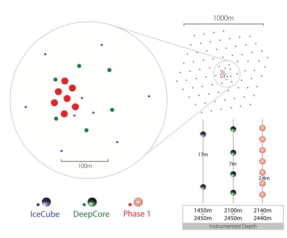
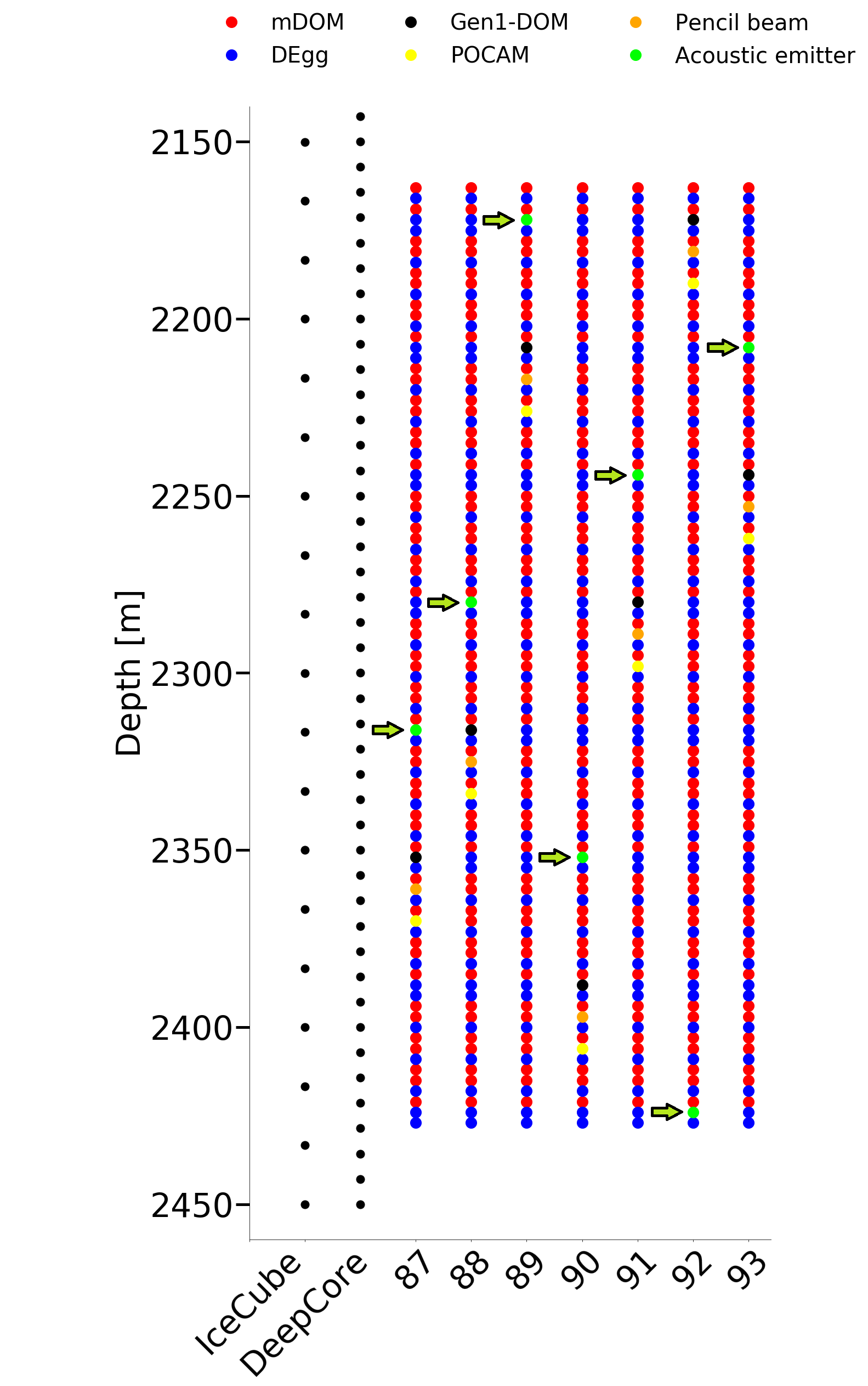
A tentative geometry with the positions of the strings, the locations of pingers and mDOMs in the dense instrumented physics region of the upgrade detector is shown in Fig.1. The positions close to optical POCAMs will allow for the direct correlation of optical and acoustic propagation times.
[\capbeside\thisfloatsetupcapbesideposition=right,bottom,capbesidewidth=5.5cm]figure[\FBwidth]
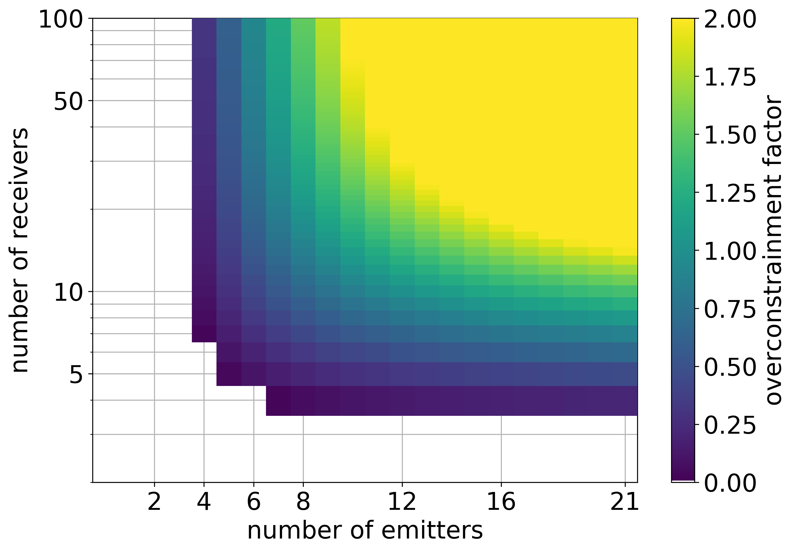
For the system design, an important consideration is the minimum number of emitters and receivers that are required for a good trilateration of the positions. Given emitters and receivers, the number of independent measurements points of transit times is . At the same time, the number of unknown parameters increases with the number of emitters and receivers. Assuming that coordinates are required for each device and that unknowns can be fixed due to the choice of the origin and orientation of an arbitrary coordinate system, the number of unknowns is . We define the overconstrainment-factor of the trilateration system as
| (1) |
Positive values correspond to a system where sufficient transit times are measured to allow for good trilateration. The overconstrainment-factor is shown in figure 2. At least pingers and receivers are required for a minimal system. For a system of emitters that are each well detected by typically 100 receiving modules an excellent overconstrainment is reached, with sufficient redundancy against module failures and systematic uncertainties. Assuming that not all receivers detect sufficiently good signals from far-away emitters, then the condition can still be satisfied as long as substantial fractions of the emitter-receiver pairs overlap222However, in this case the exact form of the above calculation of becomes more complicated. The uncertainties of the maximum distance scale for good signals will be discussed below. However, an acoustic range of the order of is fully sufficient to achieve a good overconstrainment.
2.2 Receivers
This receiver concept is based on the acoustic receivers that have been developed for the EnEx [13, 14, 15] and EnEx-RANGE [8] projects. An adaption for use in the mDOM was developed and a demonstrator has been validated inside a DOM pressure sphere and tested in water [16, 17]. Also the compatibility of the optical gel and all sensor materials was tested [17].
(a)
(b)
(c)
(d)
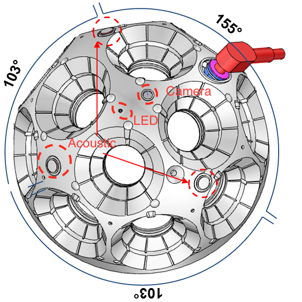
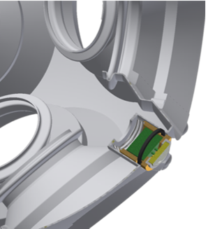
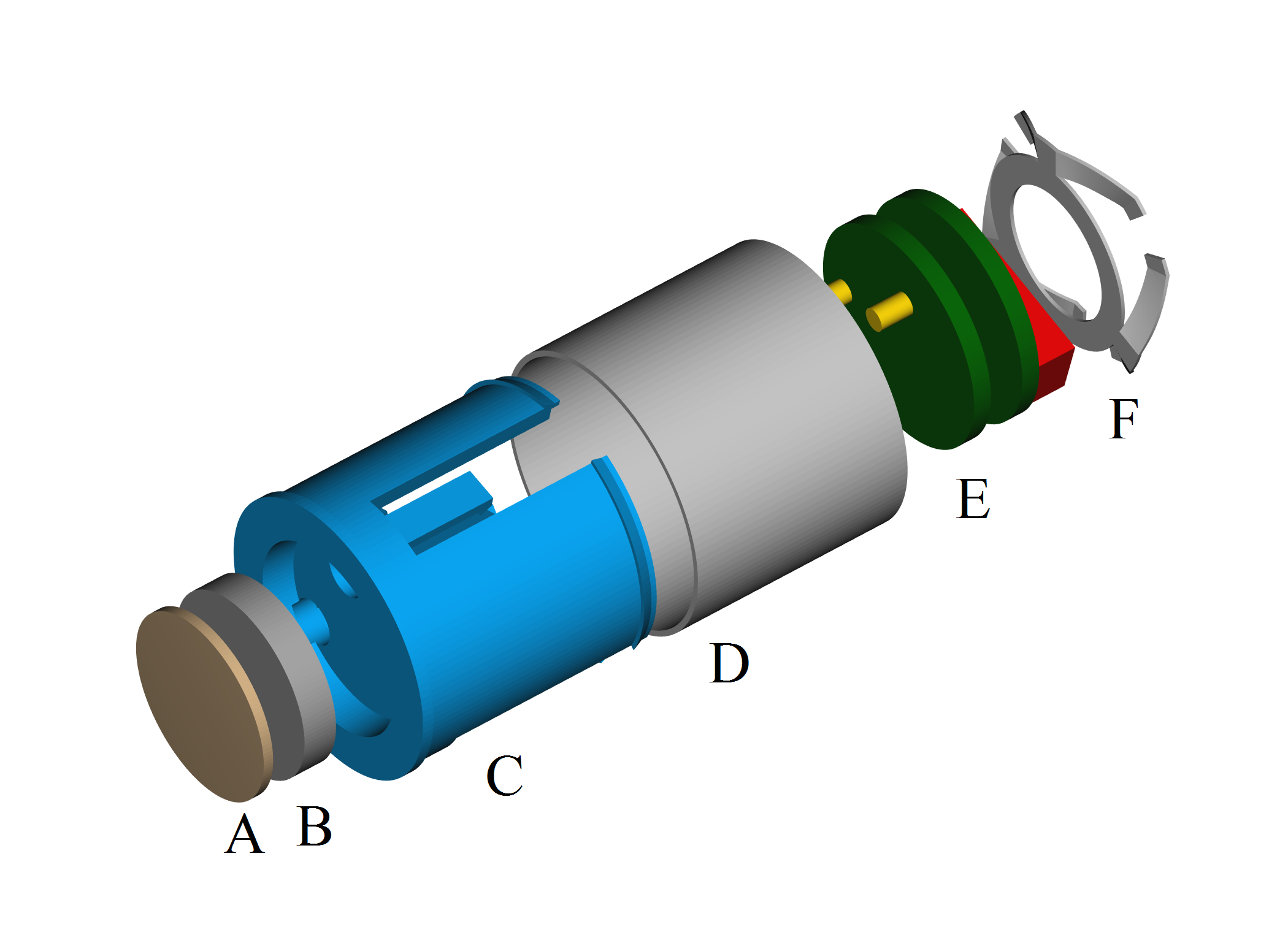
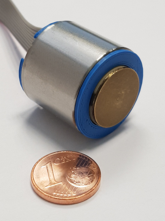
A picture of the sensor design and integration into the mDOM is shown in figure 3. The mDOM contains a mechanical holding structure for the photomultipliers to which the sensors are mounted. Three positions, well separated in azimuth direction in order to achieve a good unidirectional response (figure (a)). Note that also an alternative design using only one sensor is under consideration. The sensor will be clipped into the holding structure. The structure as well as the sensor is glued with optical gel into the pressure housing (b). The sensor is sealed with an O-ring to prevent gel from leaking into the inner structure. The mechanical components are illustrated in the exploded view (c). The transducer (B) is based on a thick and diameter lead zirconate titanate (PZT) disk (type PIC155 from PI Ceramic). Between the sensor and the glass housing is an optional coupling element made of brass improving the sensors coupling to the spherical glass housing (A). The clip (C) for mounting the sensor into the holding structure is produced by a 3d-printer. A metal housing (D) surrounds the sensor and including its electronics (E) serving as an electromagnetic shielding. An additional spring (F) ensures a small pressure between the sensor and the housing in order to maintain a good coupling during the curing of the gel. A fully mounted sensor is shown in (d). The outer diameter is and the total length is .
The sensor electronics consists of an analog front-end and the digitization electronics implemented as a two stage PCB with an connector in between. All electronics are included in the sensor package, thus making the sensor fully digital in terms of interfacing to the mDOM main electronics [4]. The mDOM mainboard provides power, SPI bus communication and synchronization.
The front-end electronics is directly coupled to the transducer, picking up the signal with two spring loaded pins. The front end electronics amplify the signal with a variable gain in the range of . This is achieved by a first stage amplifier of fixed gain and a second stage amplifier of which gain can be changed by a digital potentiometer. The amplifier circuit is built as a frequency filter with a pass band of .
The sensor is controlled by a micro-controller (Atmel ATSAMD21E18A), that handles digitization, local data storage in a RAM memory, and communication to the mDOM mainboard via a wire cable using the SPI protocol. The analog to digital conversion is done with variable frequency and resolution using an AD7276 chip. A local memory of allows the acquisition of up to of continuous data. One sensor total power consumption is about and its estimated cost around .
2.3 Pingers
The pingers are standalone devices that are attached to the strings. They are based on the design that was developed for the EnEx-RANGE project [8, 18]. A conceptual drawing is shown in figure 4. The stainless steel housing has about in diameter and in length. It holds the mechanical pinger system, the high voltage driving circuits as well as the digital circuit for control and communication to the surface. A first prototype is currently under construction.
[\capbeside\thisfloatsetupcapbesideposition=right,bottom,capbesidewidth=3.5cm]figure[\FBwidth]

In the center, a stack of ring-like piezo discs (Sonox P4 from CeramTec) of outer inner diameter and thickness is placed. They are arranged in a Tonpilz configuration with a front-mass of and an effective tail mass of . The signal is generated by a custom driving circuit that provides waveform signals of frequencies between implemented as a 3 voltage level signal with voltages of . This allows sending different types of signals, e.g. chirps and sine burst, up to of electrical power. The required energy of a long signal is then . Assuming that a continuous power of can be provided to the pinger for recharging, the maximum repetition rates is . This gives a number of pulses per day per pinger that can be measured and averaged for an improved signal-to-noise ratio of the sensor.
3 Expected performance
Estimates for the performance of the system are difficult, because they depend on parameters which are not very well known at the moment. While the glass of the sphere matches the acoustic impedance of ice and the piezo material quite well, the mechanical coupling of the sensor to the glass and the coupling of the glass to the ice under high pressure are largely unknown and the directional dependant response function cannot be calibrated prior to deployment. Furthermore, large uncertainties exist for the propagation of sound in ice. For acoustic trilateration, the most relevant properties are the damping of the signal due to attenuation and the geometric spread with distance, as well as the speed of sound that affects the arrival time.
The speed of sound can vary moderately with depth and can even vary within the horizontal plane in the case where there is a preferential crystal orientation [19]. Addressing this uncertainty is only possible with a sufficient overconstrainment factor (see above), that would allow for implementing the speed of sound as an additional fit parameter. Further information can be obtained from external inputs such as ice properties as obtained with optical devices. As the optical and acoustic trilateration methods are exposed to very different systematic uncertainties from the global ice parameters, their comparison will allow reducing these uncertainties.
The uncertainty of the sensor response within the modules can be tested within water. Water is an acoustically isotropic and homogeneous medium with negligible attenuation at the considered frequencies. Several swimming pool tests have been performed with prototype sensors that have been mounted within glass pressure spheres [16, 17]. These tests have shown that the sensors allow for position resolutions of a few . However, these tests also show that the sensor response within the glass-spheres has a complex dependency on the direction of the acoustic wave, even if coupling to the medium and the media properties are well known. This is addressed by using three sensors per mDOM alleviating the problem as this allows for internal consistency checks of the measured data such as comparing different sensor orientations with respect to the direction of the incoming acoustic beam.
Trilateration in natural ice and its spatial resolution has been evaluated within the EnEx-RANGE project. There, the location of a moving melting probe in an Alpine glacier could be determined to an accuracy of typically [20]. Taking into account that the positions in IceCube are static, the ice properties of the bulk ice are more favorable (see below), larger averaging factors of repeated wave-forms are possible yielding a better signal-to-noise ratio, and the number of sensors is higher providing a substantially larger overconstrainment factor, the above value can be considered as robust estimate of the achievable resolution in IceCube.
[\capbeside\thisfloatsetupcapbesideposition=right,bottom,capbesidewidth=3.5cm]figure[\FBwidth]
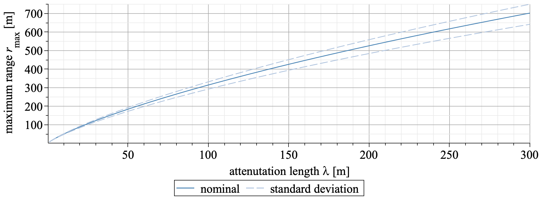
Particularly challenging is the question of acoustic attenuation in the deep ice. Data and experience from the EnEx-RANGE and SPATS can be used for an estimation. Measurements in shallow depth by SPATS indicate an attenuation length of almost [10], while EnEx-RANGE measurements [21] in a tempered Alpine glacier give smaller values of . With the ice at larger depth being of similar quality as in SPATS depth but slightly warmer in temperature, we expect an attenuation length substantially larger than for EnEx-RANGE but smaller than measured in SPATS. Trilateration data from EnEx-RANGE field tests can be used to estimate the acoustic range as a function of the estimated attenuation length as shown in figure 5. The calculation is based on measured signal-to-noise ratios of measured at distances of with signal averages in ice with an attenuation length amplitude of only . Assuming the damping of the amplitude of a spherical wave with distance is
| (2) |
the value can be fitted with the measured data. Assuming a minimum required amplitude (corresponding to the required ), the maximum range for a for good transit time measurement can be estimated by where is Lambert W function.
The result of the calculation is shown in figure 5, assuming a minimum , and otherwise the same properties as the EnEx-RANGE system. The shown uncertainty is obtained from the spread of the three best values measured in-situ. For a typical attenuation length of good transit times will be measurable up to distances of which is sufficient for the IceCube upgrade, but also for string spacings of the IceCube-Gen2. Note that more averages than the here above assumed will further enlarge the usable range.
4 Conclusion and Outlook
We have presented the design of an acoustic positioning system with the goal of measuring the position of sensors in the IceCube upgrade. The system consists of receivers that are mounted within the optical modules and stand-alone emitters of high power acoustic signals. Initial prototypes of the sensors have been produced and tested and the emitter prototype is under construction. Preliminary estimates of the performance are based on previous acoustic trilateration measurements in ice. Those indicate that the system can be scaled to string distances of more than as required for the IceCube-gen2. With the deployment of the IceCube upgrade, planned in 2022/23, precise in situ data will become available and the design of the system will be further optimized.
References
- [1] IceCube Collaboration, M. G. Aartsen et al., JINST 12 (2017) P03012.
- [2] L. Peters Bachelor’s Thesis, RWTH Aachen University, 2019. in German.
- [3] IceCube Collaboration, \posPoS(ICRC2019)1031 (these proceedings).
- [4] IceCube Collaboration, \posPoS(ICRC2019)855 (these proceedings).
- [5] IceCube Collaboration, \posPoS(ICRC2019)908 (these proceedings).
- [6] IceCube Collaboration, \posPoS(ICRC2019)928 (these proceedings).
- [7] IceCube Collaboration, \posPoS(ICRC2019)923 (these proceedings).
- [8] D. Heinen et al., EPJ Web Conf. 135 (2017) 06007.
- [9] Y. Abdou et al., Nucl. Instrum. Meth. A683 (2012) 78–90.
- [10] IceCube Collaboration, R. Abbasi et al., Astropart. Phys. 34 (2011) 382–393.
- [11] IceCube Collaboration, M. G. Aartsen et al., arXiv:1412.5106.
- [12] IceCube Collaboration, R. Abbasi et al., Astropart. Phys. 35 (2012) 312–324.
- [13] J. Kowalski et al., Cold Regions Science and Technology 123 (2016) 53–70.
- [14] D. Heinen. PhD thesis, RWTH Aachen University, 2018. in German.
- [15] D. Eliseev. PhD thesis, RWTH Aachen University, 2018.
- [16] S. Wickmann et al., EPJ Web Conf. 135 (2017) 06003.
- [17] R. Turcotte Master’s thesis, RWTH Aachen University, 2019. internal report icecube/201906001.
- [18] L. S. Weinstock. PhD thesis, RWTH Aachen University, 2019. in preparation, in German.
- [19] D. Kluskiewicz et al., Journal of Glaciology 63 (2017) 603–617.
- [20] S. Zierke. PhD thesis, RWTH Aachen University, 2019. submitted, in German.
- [21] A. Meyer et al., The Cryosphere 13 (2019) 1381–1394.