Joint Radar-Communications Strategies for Autonomous Vehicles
Abstract
Self-driving cars constantly asses their environment in order to choose routes, comply with traffic regulations, and avoid hazards. To that aim, such vehicles are equipped with wireless communications transceivers as well as multiple sensors, including automotive radars. The fact that autonomous vehicles implement both radar and communications motivates designing these functionalities in a joint manner. Such dual function radar-communications (DFRC) designs are the focus of a large body of recent works. These approaches can lead to substantial gains in size, cost, power consumption, robustness, and performance, especially when both radar and communications operate in the same range, which is the case in vehicular applications. This article surveys the broad range of DFRC strategies and their relevance to autonomous vehicles. We identify the unique characteristics of automotive radar technologies and their combination with wireless communications requirements of self-driving cars. Then, we map the existing DFRC methods along with their pros and cons in the context of autonomous vehicles, and discuss the main challenges and possible research directions for realizing their full potential.
I Introduction
Autonomous vehicles are required to navigate efficiently and safely in a wide variety of complex uncontrolled environments. To meet these requirements, such self-driving cars must be able to reliably sense and interact with their surroundings. This acquired sensory information as well as data communicated from neighboring vehicles and road-side units are essential to avoid obstacles, select routes, detect hazards, and comply with traffic regulations, all in real-time.
In order to reliably sense the environment, autonomous vehicles are equipped with multiple sensing technologies, including computer vision acquisition, i.e., cameras, light detection and ranging (LIDAR) laser-based sensors, global positioning systems, and radar transceivers. Each of these technologies has its advantages and disadvantages. In order to allow accurate sensing in a broad range of complex environments, self-driving cars should simultaneously utilize all of these aforementioned sensors. Radar for instance, provides the ability to accurately detect distant objects and is typically more robust to weather conditions and poor visibility compared to its competing sensing technologies [1].
Radar systems, which detect the presence of distant objects by measuring the reflections of electromagnetic probing waves, have been in use for over a century. Radar has been most commonly used in military applications, aircraft surveillance, and navigation systems. The application of radar for vehicles, referred to as automotive radar [2], is substantially different from traditional radar systems: Most notably, automotive radar systems, which are used by mass-produced vehicles, are far more limited in size, power, and cost. Furthermore, while conventional radar aims to detect a relatively small number of distant targets, e.g., airplanes, automotive radar is required to sense in complex dense urban environments in which a multitude of scatterers at close ranges should be accurately detected. Despite these differences, automotive radar is an established and common technology nowadays, and the vast majority of newly manufactured vehicles are equipped with radar-based autonomous driving assistance systems [1].
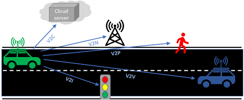
In addition to their ability to sense their environment, autonomous vehicles are also required to carry out various forms of communications, as illustrated in Fig. 1: vehicle-to-vehicle (V2V) transmissions allow self-driving cars to share their attributes with neighbouring vehicles; vehicle-to-infrastructure (V2I) messages facilitate intelligent road management by conveying information between cars and road-side units; vehicle-to-pedestrian (V2P) communications can be used to warn or alarm nearby pedestrians; Finally, service providers and cloud applications exchange possibly large amounts of data with self-driving cars via vehicle-to-network (V2N) and vehicle-to-cloud (V2C) links, respectively. The resulting broad range of different tasks, which substantially vary in their latency, throughput, and reliability requirements, can be implemented by using individual communications technologies for each application, or by using a unified vehicle-to-everything (V2X) strategy [3], possibly building upon the cellular infrastructure.
Automated cars thus implement two technologies which rely on the transmission and processing of electromagnetic signals: radar and wireless communications. A possible approach in designing self-driving cars is to use individual systems for radar and communications, each operating separately. An alternative strategy is to jointly design these functionalities as a dual function radar-communications (DFRC) system. Such schemes are the focus of extensive recent research attention [4, 5, 6, 7, 8, 9, 10, 11, 12, 13, 14, 15, 16, 17, 18, 19, 20, 21, 22, 23, 24, 25]. In particular, it was shown that jointly implementing radar and communications contributes to reducing the number of antennas [26], system size, weight, and power consumption [9], as well as alleviating concerns for electromagnetic compatibility and spectrum congestion [8]. Utilizing such joint designs in vehicular systems can mitigate the mutual interference among neighboring cars, facilitate coordination, and improve pedestrian detection [27]. These benefits make DFRC systems an attractive technology for autonomous vehicles.
While the conceptual advantages of joint radar-communications designs for autonomous vehicles are clear, the proliferation of different DFRC strategies makes it difficult to identify what scheme is most suitable for which scenario. For example, some DFRC methods use existing V2X communications waveforms as radar probing signals, thus allowing high communication throughput with relatively limited sensing capabilities [21, 22, 23]. Alternative schemes embed digital messages in the radar probing signals [20, 19], thus supporting low data rates which may be more suitable to serve as an additional channel to the standard communications functionalities of autonomous vehicles.
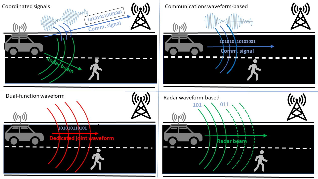
The goal of this article is to review DFRC technologies in light of the unique requirements and constraints of self-driving cars, facilitating the identification of the proper technology for different scenarios. We begin by reviewing the basics of automotive radar, identifying its main challenges, recent advances, and fundamental differences from conventional radar systems. We then survey DFRC methods, dividing previously proposed approaches into four main categories: coordinated signals transmission methods utilizing individual signals for each functionality; communications waveform-based schemes, which use the communications signal as a radar probing waveform; radar waveform-based techniques, which embed the digital message into the parameters of the radar signal; and the design of dedicated dual-function waveforms. We detail a representative set of DFRC methods for each category, and provide a map of the existing strategies in terms of their radar capabilities, information rates, and complexity.
II Basics of Automotive Radar
Past decades have witnessed growing interest in automotive radar to improve the safety and comfort of drivers. A typical ADAS implements various radar subsystems that enable functions including adaptive cruise control, blind spot detection, and parking assistance[1]. To understand the benefits of combining automotive radar with digital communications, we first review the basics of automotive radar.
Automotive radars operate under different requirements and constraints compared to conventional radars, such as those utilized in military applications and air traffic control. First, conventional radar systems are required to detect a relatively small number of targets in ranges on the order of tens or hundreds of kilometers, while automotive radars must detect a multitude of objects in short ranges on the order of a few tens of meters. Furthermore, automotive radars are incorporated into mass-produced vehicles, hence have more strict constraints on cost, size, power consumption, and spectral efficiency compared to conventional radar. Finally, automotive radars are densely deployed urban environments, thus must be robust to interference while inducing minimal interference to neighboring radar systems.
Various techniques have been proposed to overcome the aforementioned challenges. In Table I we summarize the main challenges along with the leading methods to tackle them. It is noted that no single radar scheme is suitable to handle the complete set of requirements. For example, the popular frequency-modulated continuous-wave (FMCW) waveform (see FMCW Radar on Page II), which can be operated using simplified hardware components, suffers from high sensitivity to interference; orthogonal frequency division multiplexing (OFDM) radar (described in OFDM Waveform Radar on Page III-A2), which is suitable for multiuser scenarios, tends to require relatively costly hardware compared to alternative radars.
| Requirements | Possible solutions |
|---|---|
| Operating in short ranges | Utilize separate transmit and receive antennas to process short range echoes. |
| Limited antenna size | Operate at millimeter-wave (mmWave) bands using patch antennas. |
| Increase virtual aperture (see MIMO Radar on Page III-B2). | |
| Simplified hardware | Constant envelope signalling. |
| Low-complexity de-chirp recovery, e.g., FMCW (see FMCW Radar on Page II). | |
| Low power amplifiers | Continuous or high duty cycle waveform, e.g., FMCW. |
| Interference robustness | Divide spectrum using OFDM (see OFDM Waveform Radar on Page III-A2). |
| Introduce agility (see Frequency Agile Radar on Page III-C2) to increase survivability. |
An additional aspect which should be considered in selecting an automotive radar scheme is its capability to be combined with wireless communications. The fact that self-driving cars utilize both radar and digital communications motivates their joint design as a DFRC system, as discussed in the following section.
[htb]
III Overview of Dual Function Systems
Since DFRC systems implement both radar and communications using a single device, these functionalities inherently share some of the system resources, such as spectrum, antennas, and power. Broadly speaking, existing DFRC methods can be divided into four main categories as illustrated in Fig. 2: coordinated separated signals transmission, communications waveform-based approaches, radar waveform-based schemes, and joint dual-function waveform designs. In the following, we review each of these categories, and discuss their pros and cons in the context of autonomous vehicles. Throughout this section, we consider a DFRC system jointly implementing a radar transceiver as well as the transmission of digital messages using transmit antennas (for both radar and communications) and receive antennas (for radar). For simplicity, we assume a single communications receiver equipped with a single antenna.
III-A Separate Coordinated Signals
A common DFRC approach is to utilize different signals for radar and communications, designing the functionalities to mitigate their cross interference, as illustrated in the upper-left subfigure in Fig. 2. Here, the transmitted signal can be written as
| (2) |
where is the radar probing waveform, and is the continuous-time communications signal. The ability to jointly transmit two dedicated signals with limited cross interference is typically achieved using either orthogonality boosting by division in time and/or frequency, or via spatial beamforming.
III-A1 Time/Frequency Division
Arguably the most simple method to mitigate cross interference is to allocate a different frequency band to each waveform, commonly dictated by regulated spectrum allocation, or, alternatively, a different time slot. In such cases, the signals and in (2) either reside in different bands (for frequency division), or satisfy at each time instance (for time division). Since system resources are allocated between both subsystems, these strategies inevitably result in a trade-off between radar and communications performance [24].
A straight-forward approach is to allocate the resources in a fixed or arbitrary manner. For instance, in [26], a DFRC system is achieved by using fixed non-overlapping bands and antennas. A random antenna allocation scheme is proposed in [18], jointly enhancing the radar angular resolution and the communication rates. The work [25] proposed a media access protocol for automotive DFRC systems with time and frequency division to mitigate interference with neighboring radars. These approaches assume that each functionality has its own frequency band. Using OFDM signaling, i.e., letting the entries of and represent OFDM radar and communications waveforms (see OFDM Waveform Radar on Page III-A2), respectively, allows to divide the spectrum in an optimized manner, as we detail next.
Consider a frequency band divided into subbands. The discrete-time transmitted signal from the th transmit antenna can be written as the vector . Since the spectrum is divided into radar and communications, is given by
| (3) |
where is the inverse discrete Fourier transform matrix; the vectors and denote the OFDM radar and communications symbols, respectively, in the frequency domain; and is a diagonal matrix of size with elements 0 or 1, representing the subcarrier selection at the th element.
Setting the matrix in (3) determines how the bandwidth is divided. The work [28] showed that when represents spectral interleaving, i.e., the support of its diagonal consists of multiple bulks of zeros and ones, radar resolution is comparable to that using the complete spectrum. When the DFRC system has a-priori knowledge of the statistical model of the radar target response and the communications channel, the subcarrier selection matrix can be set to optimize a linear combination of the radar target-echo mutual information and the communications input-output mutual information, as proposed in [17].
III-A2 Spatial Beamforming
The utilization of multiple antennas enables to mitigate the mutual interference through spatial beamforming, for example, by projecting the radar waveform into the null space of its channel to the communications receiver [29], resulting in a zero forcing beamformer. While such beamforming was originally proposed for separate systems, it can also be utilized for a DFRC system.
In this model, the communications and radar signals are beamformed using the matrices and , respectively, in order to mitigate the mutual interference while satisfying the performance constraints. The signals received at the communications receiver and the radar target with direction are thus
| (4) |
where is the channel response from the DFRC transmitter to the communications receiver, and is the steering vector of the DFRC transmitter to the radar target in direction . Using the formulation (4), the beamforming matrices and are jointly designed to mitigate cross interference while satisfying the performance requirements, e.g., maximize the signal-to-interference-plus-noise ratio (SINR) at the communications receiver while meeting a given radar beampattern [30].
A clear advantage of the separated signals transmission strategy is that it can provide a wide variety of possible performance combinations. For time/frequency division schemes, the performance is determined by how the system resources, such as spectrum and time slots, are allocated to each functionality. The performance trade-offs may be potentially improved using spatial beamforming, allowing each functionality to utilize the full bandwidth and operate simultaneously at all time slots. However, the spatial beamformer is designed based on a-priori channel knowledge, which may be unavailable for fast moving vehicles. According to the discussions above, time/frequency division-based schemes are likely to be more attractive in automotive applications. Since properly optimizing the resource allocation to achieve a desired performance trade-off requires considerable computation, fixed sub-optimal allocations, such as spectral interleaving, may be preferable.
[htb]
III-B Communications Waveform-Based Schemes
Another common DFRC strategy is to utilize standard communications signals for probing, as illustrated in the upper-right subfigure in Fig. 2. The majority of communications waveform-based designs in the literature utilize OFDM signalling, especially for automotive applications. In the sequel, we first briefly review spread spectrum based DFRC systems, followed by a more detailed presentation of shared OFDM waveforms, and a description how structured vehicular communications protocols can be used for sensing.
III-B1 Spread Spectrum Waveforms
Spread spectrum techniques transmit a communications signal with a given bandwidth over a much larger spectral band, typically using spread coding or frequency hopping. The usage of spread spectrum signals for radar probing was studied in [12]. The main drawback of spread spectrum DFRC design is that the radar dynamic range is limited, which is a byproduct of the imperfect auto-correlation properties of the spreading sequences[12]. In addition, accurately recovering the target velocity from spread spectrum echoes is typically computationally complex, limiting the applicability of such DFRC systems. Finally, high speed ADCs is required for wideband spectrum spread waveforms, as de-chirp used in FMCW is not applicable, increasing cost and complexity.
III-B2 OFDM Waveforms
The most common communications waveform-based approach is to utilize OFDM signalling. OFDM is a popular digital communications scheme due to its spectral efficiency, inherent ability to handle inter-symbol interference, and the fact that it can be implemented using relatively simple hardware components[34]. Since first proposed in [35], OFDM has received extensive attention as a radar waveform, especially for automotive radar, due to its high flexibility, adaptability in transmission, and since, unlike FMCW, it does not suffer from range-Doppler coupling [36]. The fact that OFDM is commonly utilized in both radar and communications indicates its potential for DFRC systems.
Compared with case where the coefficients in the OFDM waveform are specifically designed for radar (see OFDM Waveform Radar on Page III-A2), the complex weights of the dual-function OFDM waveform are the communications symbols. The setting of the waveform parameters can have a notable effect on each functionality. The work [37] designed the sub-carrier spacing according to the maximum unambiguous range and the maximum velocity. In [9] channel knowledge was used to allocate power between the subcarriers to maximize the sum of the data rate and the mutual information between the received echoes and the target impulse response. Radar processing of OFDM waveforms utilizes matched filtering, which depends on the transmitted data, causing high level sidelobes. This data dependency can be eliminated by dividing each subcarrier by its corresponding symbol [12]. The range and velocity of each target are then estimated using a two dimensional DFT in the carrier domain and slow time domain (between different symbols), respectively.
OFDM can be naturally combined with multiple-input multiple-output (MIMO) radar which transmits orthogonal waveforms from each antenna (see MIMO Radar on Page III-B2) by assigning different subcarriers to different transmit elements. Several works have studied how to divide the subcarriers among the elements. The proposed methods include division by equidistant sub-carrier interleaving [28]; non-equidistant subcarrier interleaving[38]; and random assignments [39].
A drawback of using shared OFDM waveforms in vehicular systems stems from the fact, when utilized from moving vehicles, OFDM exhibits subcarrier misalignment, degrading the maximal radar unambiguous range [36]. Additional drawbacks are related to hardware constraints: Wideband OFDM waveforms require high rate ADCs, affecting the system cost and power consumption. Another hardware limitation of OFDM compared to monotone waveforms is its high peak-to-average power ratio, inducing distortion in the presence of practical non-linear amplifiers. A weighted OFDM method was proposed to control the maximum peak-to-average power ratio[32, 33]. In order to utilize OFDM with narrowband transmissions, one can apply stepped frequency methods, as proposed in [40].
[htb]
III-B3 Protocol-Oriented DFRC Methods
An alternative strategy is to exploit the existing communications protocols, utilizing them as an automotive radar waveform. Here, there is no compromise in the communications part, and the radar functionality is a byproduct of the protocol, which is typically IEEE 802.11p or IEEE 802.11ad [21, 22, 23, 42, 43, 44]. The IEEE 802.11p standard focuses on vehicular communications, and supports short range device-to-device transmissions for safety applications. This protocol operates in the band and uses OFDM signaling. Consequently, its transmissions realize a DFRC system with an OFDM shared waveform, as proposed in [21].
IEEE 802.11ad is a generic standard for short range mmWave communications operating at . Its large bandwidth enables higher data rates for communications, and better accuracy/resolution for radar operation. In order to avoid the usage of data-dependent waveforms, it has been proposed to utilize the a-priori known IEEE 802.11ad preamble for radar probing [22, 23, 42]. As the preamble now affects radar performance, the work [43] studied the design of radar suitable preamble sequences. In such mmWave communications, highly directional beams are used. Once the communications data link is established, radar can only reliably detect targets located in the assigned beam direction. Several approaches have been proposed to extend the scanning area at the cost of power reduction in [44].
The main benefit of protocol-based DFRC designs is that they implement radar with minimal effect on the communications functionality. As such, its radar capabilities are quite limited. The radar coverage area is restricted by the directionally beamformed mmWave transmission. In addition to its restricted coverage area, the scheme has a relatively low radar duty cycle as only the preamble is utilized for probing, limiting its detection range in vehicular systems operating under peak power constraints.
To conclude, communications waveform-based DFRC approaches, and particularly using shared OFDM signalling, enable transmitting high data rates by utilizing conventional digital communications schemes. The fact that OFDM is widely studied for both radar and communications makes it an attractive DFRC design. In the context of autonomous vehicles, several drawbacks must be accounted for: First, in order to radiate enough power on the target, radar waveforms are typically beamformed to be directional. The communications receivers should thus be located in the radar beam in order to observe high signal-to-noise ratios. Such transmissions may thus be more suitable to serve as a secondary communications channel, in addition to a possible cellular-based V2X technology which can communicate with the receivers in the omnidirection. Similarly, protocol-oriented schemes, which utilize standard communications transmission while exploiting its structure for probing, is more likely to provide additional sensing capabilities to a dedicated automotive radar. Finally, relatively costly hardware components are required for generating wideband waveforms and sampling their reflections. Despite these drawbacks, sensing using communications waveforms is considered to be a promising DFRC approach for autonomous vehicles [1].
III-C Radar Waveform-Based Techniques
DFRC systems can also be designed by embedding the communication message in conventional radar waveforms, as illustrated in the bottom-right subfigure in Fig. 2. These techniques are divided into two categories: The first approach modifies the radar waveform to incorporate digital modulations; the second method utilizes index modulation (IM), conveying data bits via the indices of certain radar parameters.
III-C1 Modified Radar Waveforms
A possible approach to embed digital communications into an existing radar system is to modify the waveform to include modulated symbols. For example, the traditional FMCW (see FMCW Radar on Page II) can be modified to include phase-modulated symbols by replacing the th pulse , defined in the box on Page II, with , where encapsulates the information message in the form of, e.g., continuous phase modulation as proposed in [45]. Alternatively, the linear frequency of the pulse can convey information via frequency modulation [46], for example, by using a positive frequency modulation rate to transmit the bit and a negative value for . While these schemes are typically power efficient [12] and with low complexity, their communication rate is very limited.
Higher communication rates can be obtained by utilizing multiple orthogonal waveforms and beamforming. Assume orthogonal waveforms are simultaneously transmitted from an antenna array, and let be the corresponding beamforming vectors. The transmit signal is expressed as . In the communications receiver, the received signal is , where and are the channel response and additive noise, respectively. By applying matched filtering with the orthogonal waveforms, the receiver obtains the vector , where . The communication data bits can be conveyed by modulating the amplitude[10] or phase[11] of . Although the communication rates are improved by transmitting multiple waveforms, the system complexity is also increased, and the transmitter must have a-priori knowledge of the communications channel . Furthermore, it is difficult to guarantee that the envelope of the transmit signal is constant modulus, which may reduce power efficiency in transmission.
III-C2 IM-Based Techniques
IM is a promising communications technique, gaining growing interest due to its high energy and spectral efficiency[47]. Instead of using conventional modulations, IM embeds data bits into the indices of certain transmission building blocks[47]. These building blocks, including spatial allocation and frequency division, are also important waveform parameters for radar. IM-based DFRC techniques thus embed the digital message into the combination of radar waveform parameters. The term index represents the radar parameters, such as carrier frequency, time slot, antenna allocation, or orthogonal waveforms in MIMO radar with orthogonal waveforms. Consequently, such DFRC systems use unmodified conventional radar schemes, and the ability to communicate is encapsulated in the parameters of the transmission. While IM-based DFRC schemes are the focus of ongoing research, existing methods typically build upon either MIMO radar or frequency agile radar (FAR) schemes. While MIMO radar can in general utilize orthogonal or non-orthogonal waveforms, we henceforth use the term MIMO radar for such schemes utilizing orthogonal waveforms, which is the typical approach in MIMO radar[41] .
[htb]
IM for MIMO radar: The work [52] proposed to combine MIMO radar with IM by embedding the bits in the assignment of the orthogonal waveforms across the transmit antennas. For a MIMO radar with transmitting antennas, there are possible arrangements in each PRI, supporting a maximal rate of bits per PRI. In [53], this approach was extended to sparse array MIMO radar configurations, where only out of transmit elements are active in each PRI. As a consequence, it requires only transmit orthogonal waveforms, represented (with a slight notation abuse) by the vector . The transmitted vector in the th PRI is a permutation of , i.e., it is given by , where is a permutation matrix, and is the antenna selection matrix which has a single non-zero entry in each row. When the channel is memoryless, the signal received at the communications receiver is
| (10) |
where is the channel vector, and is the additive noise. After matched filtering with the orthogonal waveforms, the obtained vector can be written as
| (11) |
The communication message can be embedded in in (11), i.e., the product of permutation matrix and the selection matrix. As there are kinds of antenna selection pattern and kinds of waveform permutations, up to bits can be encapsulated in each PRI.
IM via FAR: FAR (see Frequency Agile Radar on Page III-C2) is a radar scheme designed for congested environments. The carrier frequencies of FAR change randomly from pulse to pulse, allowing to achieve an ergodical wideband coverage, while utilizing narrowband waveforms and enabling to mitigate interference from neighbouring radars. The work [54] proposed a DFRC system which embeds a digital message into the permutation of the agile carrier frequencies. For a carrier set with different carrier frequencies, there are different carrier frequency permutations that can be utilized for information embedding.
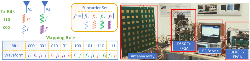
In [20, 19], a DFRC system is proposed based on multi-carrier agile waveforms and IM. Unlike traditional FAR, here multiple carriers are simultaneously sent from several sub-arrays of transmit antennas. For a DFRC system with transmit antenna elements and a possible carrier frequency set of cardinality , the corresponding information embedding consists of two stages: In the th pulse, carriers, denoted by the set , are first selected from . Then, the antenna array is divided into sub-arrays, where each sub-array has elements. The transmitted signal of the multi-carrier frequency agile DFRC system in the th PRI is expressed as
| (12) |
where is the beam steered direction, is the radar beamforming vector for the th carrier with frequency , and is the selection matrix which determines the transmit antennas of carrier with frequency . The communication message is embedded into the antenna allocation pattern as well as the selection of carrier frequencies. The number of antenna allocation patterns is , and there are possible combinations of carrier selections. Hence, the total number of transmission patterns that can be used for information embedding is . An illustration of this scheme, as well as a hardware prototype designed to demonstrate its feasibility, are shown in Fig. 3.
Since IM-based DFRC systems utilize conventional radar waveforms, radar detection is carried out using standard methods. For example, FAR detection is based on matched filtering followed by compressed sensing recovery [55]. Symbol detection at the communications receiver can be realized using the maximum likelihood rule, or alternatively, via a reduced complexity IM detector, see, e.g., [19].
The main advantage of radar waveforms-based DFRC methods is that they provide the ability to communicate with minimal degradation to the performance of the radar scheme from which the technique originates. For example, the radar performance of MIMO radar as well as FAR combined with IM are roughly equivalent to their radar-only counterparts [20], respectively. In particular, FAR is attractive for automotive radar due to its inherent applicability in congested setups and compliance with simplified hardware. Nonetheless, the communications functionality of radar waveform-based DFRC systems is relatively limited in throughput, and typically results in increased decoding complexity, making it more suitable to serve as an alternative channel in addition to existing, e.g., cellular-based, vehicular communications, rather than replacing the latter.
III-D Joint Waveform Design
The approaches detailed so far are all based on traditional radar and/or communications signalling. A DFRC system is then obtained by either designing the conventional waveforms to coexist, as detailed in Subsection III-A, or alternatively, by using only one standard waveform while extending it to be dual-functional. Using traditional signalling has clear advantages due to their established performance and applicability with existing hardware devices. Nonetheless, the fact that these waveforms were not originally designed for DFRC scenarios implies that one can achieve improvement by deriving dedicated dual-function waveforms, as illustrated in the bottom-left subfigure of Fig. 2.
Dedicated joint waveforms, which do not originate from conventional radar / communications signalling, are designed according to a dual-function objective which accounts for the performance of both radar and communications [13, 14, 15]. Here, the transmitted joint signal is denoted by the matrix , where is the block length. We focus on a multi-user scenario with single antenna receivers. The signal received at the receivers and at the radar target with direction can be expressed as
| (13) |
where is an channel matrix, is the joint beamformer, and is the additive noise term.
Using formulation (13), one can design the joint waveform in order to approach some desired observations at the communications receivers as well as the radar target, as proposed in [13]. A possible drawback is that the signals received in other directions are not constrained, and thus the radar transmit beampattern may have a high sidelobe level outside the mainlobe. This can be overcome by restricting the radar beampattern[14, 15], which is in turn achieved by constraining the signal covariance. In particular, [14] considered to be a communications signal and optimized the joint precoding to approach a pre-defined beampattern while meeting a minimal SINR level at each receiver. The work [15] designed the joint waveform to minimize the multi-user interference under specific radar constraints, such as omindirectional or directional beampatterns, constant modulus designs, and waveform similarity.
Dual function waveforms specifically designed for DFRC offer to balance radar and communications in a controllable manner. Furthermore, using joint optimization, without being restricted to conventional waveforms, can potentially yield any achievable performance tradeoff between radar and communications. Despite these clear theoretical benefits, their application in automotive DFRC system is still limited to date due to practical considerations. For example, current joint waveforms designs involve solving a relatively complex optimization problem, which depends on prior channel knowledge. In fast moving vehicles, accurate instantaneous channel knowledge is difficult to obtain, and even when it is available, the optimization process must be frequently repeated, inducing increased computational burden.
III-E Discussion
The DFRC methods surveyed here vary significantly in their characteristics such as radar performance, communication throughput, complexity, and hardware requirements. Although several efforts have been made in the literature to characterize the achievable radar-communications trade-off in DFRC systems [4, Ch. VI], to date there is no unified joint measure which allows to rigorously evaluate different schemes.
To demonstrate the challenge in comparing DFRC methods, we numerically evaluate two promising schemes: OFDM waveforms, which utilize communications signaling for radar probing, and the radar-based IM via FAR method. In particular, we consider a single antenna automotive radar in the GHz band divided into bins, using the same configuration as in [12]. OFDM utilizes the complete frequency band, while IM-FAR uses a single subcarrier at each instances, embedding the message in its selected index, i.e., a total of bits per symbol. To guarantee that both methods operate with the same data rate, we group the OFDM subcarriers into distinct blocks, and assign a binary phase shift keying symbol to each block. Both schemes use the same pulse width, PRI, and power, attempting to recover a point target with range [m] and relative velocity [m/s], while communicating over a Rayleigh flat fading channel. The resulting normalized mean-squared error (MSE) in target range recovery, as well as the communications bit error rate, are depicted in Fig. 4. Observing Fig. 4 we note that OFDM achieves improved communications performance over IM-FAR, while their radar performance is relatively similar. The results in Fig. 4, which are in favor of OFDM-based DFRC systems, are relevant for interference free scenarios, where a single DFRC system probes the environment. In dense scenarios with multiple interfering devices, which model automotive systems in urban settings, FAR is expected to be more capable of mitigating the mutual interference due to its random spectral sparsity [20].
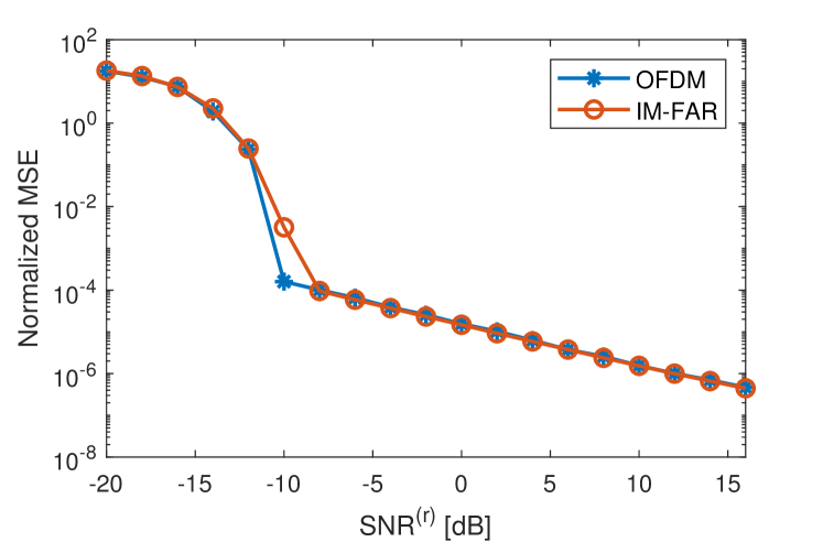
(a) Normalized MSE in range estimation
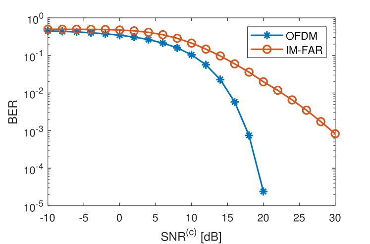
(b) Bit error rate
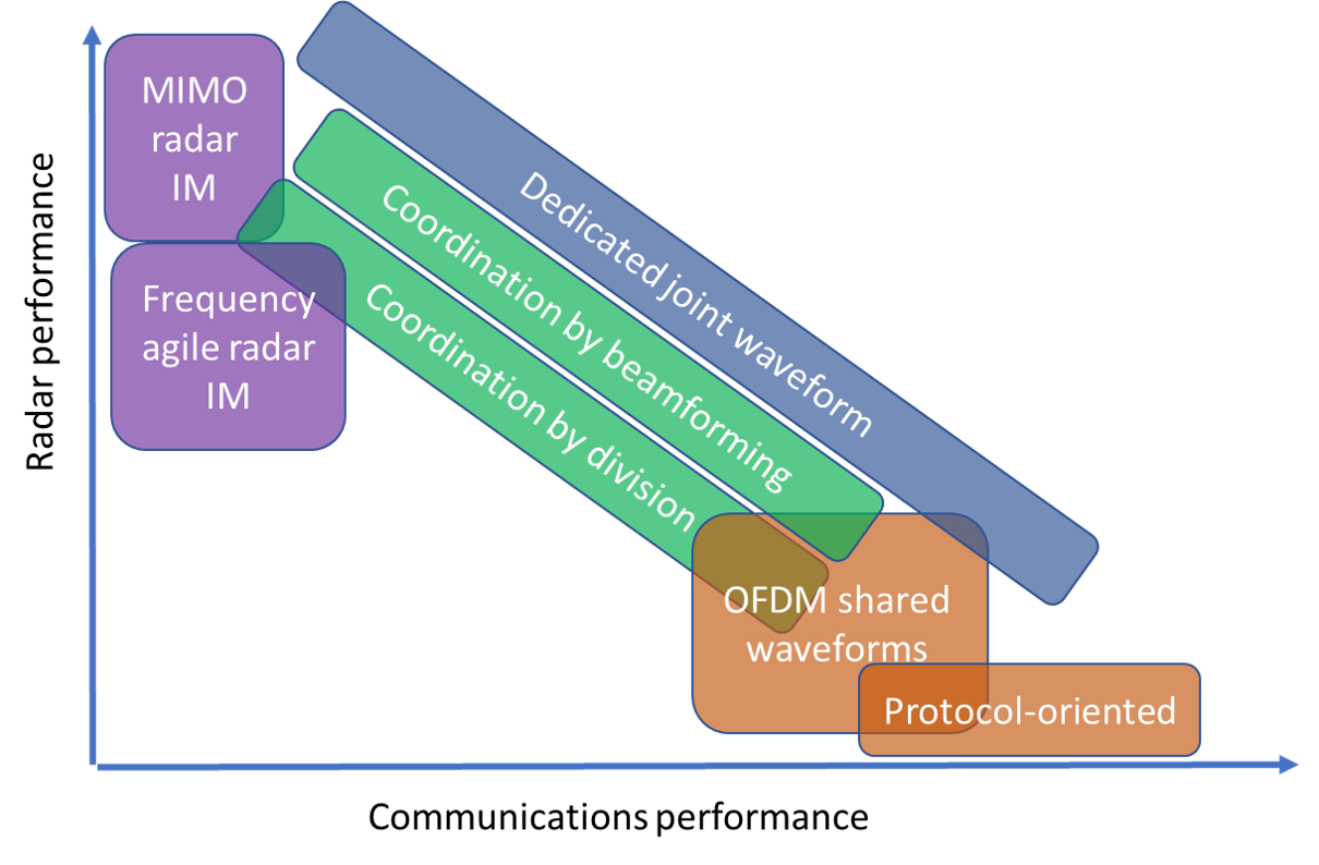
Due to the difficulty in comparing DFRC schemes, we schematically evaluate their radar vs. communications performance trade-off in Fig. 5. Separate coordinated transmission methods, which utilize individual signals for each functionality, support a broad range of possible performance combinations, determined by how the system resources are allocated between the functionalities. In particular, beamforming techniques, which require a-priori channel knowledge, allow the signals to utilize the full bandwidth and operation time, and thus have the potential to achieve improved performance compared to time/frequency division strategies. Nonetheless in the presence of multiple scatterers and communications receivers, which is the case in vehicular applications, obtaining accurate channel knowledge and mitigating mutual interference by beamforming may be infeasible, while spectral division can be applied with controllable complexity regardless of the number of receivers and their physical location.
Communications waveform-based approaches, particularly when using OFDM transmission, support high data rates by utilizing conventional digital communications signals. Specifically, OFDM is a digital communications scheme which has some of the characteristics of good radar waveforms. In the context of autonomous vehicles, a major limitation of this approach is that, since a single directed beam is used, the receiver should be located in the radar search area. Furthermore, OFDM transmission requires relatively costly hardware, and its radar capabilities are degraded when utilized by a moving vehicle.
Protocol-oriented approaches, being an extreme case of using a communications waveform for radar probing, offer to utilize existing vehicular communications protocols for sensing. They provide minimal communications degradation with limited radar capabilities. As such, these methods can be considered as an additional sensing technology, which should not replace dedicated automotive radar.
Radar waveform-based schemes, especially IM-based DFRC systems, can be naturally integrated into automotive radar systems with minimal effect to their performance. While MIMO radar implementing instantaneous wideband waveforms offers improved radar performance over frequency agile waveforms, the latter may be preferable to vehicular applications due to its robustness to congested environments and reduced complexity. Nonetheless, the limited bit-rates of IM and its associated decoding complexity make such DFRC schemes more suitable to provide an additional communications channel, independent of the cellular network. The usage of such channels for safety and emergency messages can be valuable in autonomous vehicles, increasing the probability of their successful transmission.
Joint waveform design techniques optimize a dual-function waveform in light of a combined constraints on each functionality. This joint approach has the potential of achieving any given tradeoff between radar and communications performances. Nonetheless, being a relatively new field of study, current dual function designs may not be suitable for automotive applications. In particular, current designs require instantaneous channel knowledge, limiting their application for self-driving vehicles.
To conclude, there is no single DFRC method which is suitable for all scenarios and requirements encountered in autonomous vehicle applications. Understanding the advantages and disadvantages of each approach will allow engineers to properly select the technologies incorporated into future self-driving cars.
IV Conclusions And Future Challenges
Autonomous vehicles implement wireless communications as well as automotive radar, which both require the transmission and reception of electromagnetic signals. Jointly designing these functionalities as DFRC system provides potential gains in performance, size, cost, power consumption, and robustness, making it an attractive approach for autonomous vehicles. In this survey, we reviewed state-of-the-art in DFRC designs focusing on their application for autonomous vehicles. To that aim, we first reviewed the basics of automotive radars, briefly discussing associated radar waveforms such as FMCW, frequency agile, and MIMO radar. The detailed intoductions of these waveforms and MIMO radar are given in the boxes acorss the paper. Then, we mapped existing DFRC strategies, proposing their division into four main categories: Coexistence schemes which utilize independent waveforms for each functionality; communications waveform-based approaches where conventional communications signals are used for radar probing; radar waveform-based schemes which embed the digital message into standard radar technologies, and joint waveform design approaches which achieve the DFRC system by deriving dedicated dual-function waveforms. The pros and cons of each category were analyzed according to the radar and communications requirements in vehicular scenarios. While we conclude that no single DFRC scheme is suitable for all the scenarios in self-driving, our analysis can significantly facilitate the design of sensing and communications technologies for future autonomous vehicles.
While joint radar-communications designs have been studied for over a decade, they still give rise to a multitude of unexplored research directions, particularly in the context of autonomous vehicles. On the theoretical side, the lack of a unified performance measure makes it difficult to compare approaches, and one must resort to heuristic arguments, as done in this article. Such an analysis will also uncover the fundamental limits of DFRC designs, characterizing their optimal gain over well-studied separate systems. From an algorithmic perspective, the utilization of joint non-standard radar and communications waveforms, utilized in some of the aforementioned strategies, can be facilitated by the development of dedicated recovery and decoding algorithms. For conventional waveforms, such as OFDM signals, efficient allocation of resources to optimize both functionalities is a relatively fresh area of study. Additionally, the presence of multiple sensing vehicular technologies, such as vision-based sensing and LIDAR, along with the ability to communicate with neighbouring devices which also sense their environment, give rise to potential improved understanding of the surroundings by properly combining these technologies. Finally, on the practical side, future investigations are required to implement these strategies in vehicular platforms and test their performance in real road environments. Such combined studies should allow to characterize the benefits and limitations of DFRC systems for self-driving cars, allowing their theoretical potential to be translated into performance gains in this emerging and exciting technology.
References
- [1] S. M. Patole, M. Torlak, D. Wang, and M. Ali, “Automotive radars: A review of signal processing techniques,” IEEE Signal Process. Mag., vol. 34, no. 2, pp. 22–35, mar 2017.
- [2] H. H. Meinel, “Evolving automotive radar–From the very beginnings into the future,” in Proc. EuCAP, 2014, pp. 3107–3114.
- [3] X. Wang, S. Mao, and M. X. Gong, “An overview of 3GPP cellular vehicle-to-everything standards,” GetMobile: Mobile Computing and Communications, vol. 21, no. 3, pp. 19–25, 2017.
- [4] B. Paul, A. R. Chiriyath, and D. W. Bliss, “Survey of RF communications and sensing convergence research,” IEEE Access, vol. 5, pp. 252–270, 2017.
- [5] K. V. Mishra, M. R. Bhavani Shankar, V. Koivunen, B. Ottersten, and S. A. Vorobyov, “Toward millimeter-wave joint radar communications: A signal processing perspective,” IEEE Signal Process. Mag., vol. 36, no. 5, pp. 100–114, Sep. 2019.
- [6] A. Gameiro, D. Castanheira, J. Sanson, and P. P. Monteiro, “Research challenges, trends and applications for future joint radar communications systems,” Wireless Personal Communications, vol. 100, no. 1, pp. 81–96, 2018.
- [7] L. Han and K. Wu, “Joint wireless communication and radar sensing systems–state of the art and future prospects,” IET Microwaves, Antennas & Propagation, vol. 7, no. 11, pp. 876–885, 2013.
- [8] A. Hassanien, M. G. Amin, Y. D. Zhang, and F. Ahmad, “Signaling strategies for dual-function radar communications: an overview,” IEEE Aerosp. Electron. Syst. Mag., vol. 31, no. 10, pp. 36–45, October 2016.
- [9] Y. Liu, G. Liao, J. Xu, Z. Yang, and Y. Zhang, “Adaptive OFDM integrated radar and communications waveform design based on information theory,” IEEE Commun. Lett., vol. 21, no. 10, pp. 2174–2177, October 2017.
- [10] A. Hassanien, M. G. Amin, Y. D. Zhang, and F. Ahmad, “Dual-function radar-communications: Information embedding using sidelobe control and waveform diversity,” IEEE Trans. Signal Process., vol. 64, no. 8, pp. 2168–2181, April 2016.
- [11] A. Hassanien, M. G. Amin, Y. D. Zhang, F. Ahmad, and B. Himed, “Non-coherent PSK-based dual-function radar-communication systems,” in Proc. IEEE RadarConf, May 2016, pp. 1–6.
- [12] C. Sturm and W. Wiesbeck, “Waveform design and signal processing aspects for fusion of wireless communications and radar sensing,” Proc. IEEE, vol. 99, no. 7, pp. 1236–1259, 2011.
- [13] P. M. McCormick, S. D. Blunt, and J. G. Metcalf, “Simultaneous radar and communications emissions from a common aperture, part I: Theory,” in Proc. IEEE RadarConf, May 2017, pp. 1685–1690.
- [14] F. Liu, C. Masouros, A. Li, H. Sun, and L. Hanzo, “MU-MIMO communications with MIMO radar: From co-existence to joint transmission,” IEEE Trans. Wireless Commun., vol. 17, no. 4, pp. 2755–2770, April 2018.
- [15] F. Liu, L. Zhou, C. Masouros, A. Li, W. Luo, and A. Petropulu, “Toward dual-functional radar-communication systems: Optimal waveform design,” IEEE Trans. Signal Process., vol. 66, no. 16, pp. 4264–4279, Aug 2018.
- [16] L. Zheng, M. Lops, Y. C. Eldar, and X. Wang, “Radar and communication coexistence: An overview: A review of recent methods,” IEEE Signal Process. Mag., vol. 36, no. 5, pp. 85–99, 2019.
- [17] M. Bicǎ and V. Koivunen, “Multicarrier radar-communications waveform design for RF convergence and coexistence,” in Proc. IEEE ICASSP, May 2019, pp. 7780–7784.
- [18] D. Ma, T. Huang, Y. Liu, and X. Wang, “A novel joint radar and communication system based on randomized partition of antenna array,” in Proc. IEEE ICASSP, April 2018, pp. 3335–3339.
- [19] T. Huang, N. Shlezinger, X. Xu, Y. Liu, and Y. C. Eldar, “MAJoRCom: A dual-function radar communication system using index modulation,” arXiv preprint arXiv:1909.04223, 2019.
- [20] T. Huang, N. Shlezinger, X. Xu, D. Ma, Y. Liu, and Y. C. Eldar, “Multi-carrier agile phased array radar,” arXiv preprint arXiv:1906.06289, 2019.
- [21] L. Reichardt, C. Sturm, F. Grünhaupt, and T. Zwick, “Demonstrating the use of the IEEE 802.11p car-to-car communication standard for automotive radar,” in Proc. EuCAP, March 2012, pp. 1576–1580.
- [22] P. Kumari, N. Gonzalez-Prelcic, and R. W. Heath, “Investigating the IEEE 802.11ad standard for millimeter wave automotive radar,” in Proc. IEEE VTC, Sep. 2015, pp. 1–5.
- [23] P. Kumari, J. Choi, N. González-Prelcic, and R. W. Heath, “IEEE 802.11ad-based radar: An approach to joint vehicular communication-radar system,” IEEE Trans. Veh. Technol., vol. 67, no. 4, pp. 3012–3027, April 2018.
- [24] A. R. Chiriyath, B. Paul, and D. W. Bliss, “Radar-communications convergence: Coexistence, cooperation, and co-design,” IEEE Trans. Cogn. Commun. Netw., vol. 3, no. 1, pp. 1–12, 2017.
- [25] C. Aydogdu, M. F. Keskin, N. Garcia, H. Wymeersch, and D. W. Bliss, “Radchat: Spectrum sharing for automotive radar interference mitigation,” arXiv preprint arXiv:1908.08280, 2019.
- [26] G. C. Tavik, C. L. Hilterbrick, J. B. Evins, J. J. Alter, J. G. Crnkovich, J. W. de Graaf, W. Habicht, G. P. Hrin, S. A. Lessin, D. C. Wu, and S. M. Hagewood, “The advanced multifunction RF concept,” IEEE Trans. Microw. Theory Techn., vol. 53, no. 3, pp. 1009–1020, March 2005.
- [27] C. Aydogdu, N. Garcia, and H. Wymeersch, “Improved pedestrian detection under mutual interference by FMCW radar communications,” in Proc. IEEE PIMRC, 2018, pp. 101–105.
- [28] C. Sturm, Y. L. Sit, M. Braun, and T. Zwick, “Spectrally interleaved multi-carrier signals for radar network applications and multi-input multi-output radar,” IET Radar, Sonar Navigation, vol. 7, no. 3, pp. 261–269, March 2013.
- [29] S. Sodagari, A. Khawar, T. C. Clancy, and R. McGwier, “A projection based approach for radar and telecommunication systems coexistence,” in Proc. IEEE GLOBECOM, Dec 2012, pp. 5010–5014.
- [30] X. Liu, T. Huang, Y. Liu, and J. Zhou, “Joint transmit beamforming for multiuser MIMO communication and MIMO radar,” arXiv:1912.03420, 2019.
- [31] D. Garmatyuk, J. Schuerger, and K. Kauffman, “Multifunctional software-defined radar sensor and data communication system,” IEEE Sensors J., vol. 11, no. 1, pp. 99–106, 2010.
- [32] T. Huang and T. Zhao, “Low PMEPR OFDM radar waveform design using the iterative least squares algorithm,” IEEE Signal Processing Letters, vol. 22, no. 11, pp. 1975–1979, Nov 2015.
- [33] A. Turlapaty, Y. Jin, and Y. Xu, “Range and velocity estimation of radar targets by weighted OFDM modulation,” in Proc. IEEE RadarConf, May 2014, pp. 1358–1362.
- [34] T. Hwang, C. Yang, G. Wu, S. Li, and G. Ye Li, “OFDM and its wireless applications: A survey,” IEEE Trans. Veh. Technol., vol. 58, no. 4, pp. 1673–1694, 2009.
- [35] N. Levanon, “Multifrequency complementary phase-coded radar signal,” IEE Proceedings-Radar, Sonar and Navigation, vol. 147, no. 6, pp. 276–284, 2000.
- [36] G. Franken, H. Nikookar, and P. V. Genderen, “Doppler tolerance of OFDM-coded radar signals,” in Proc. EuRAD, 2006.
- [37] M. Braun, C. Sturm, A. Niethammer, and F. K. Jondral, “Parametrization of joint OFDM-based radar and communication systems for vehicular applications,” in Proc. IEEE PIMRC, 2009.
- [38] G. Hakobyan and B. Yang, “A novel OFDM-MIMO radar with non-equidistant dynamic subcarrier interleaving,” in Proc. EuRAD, Oct 2016, pp. 45–48.
- [39] C. Knill, F. Roos, B. Schweizer, D. Schindler, and C. Waldschmidt, “Random multiplexing for an MIMO-OFDM radar with compressed sensing-based reconstruction,” IEEE Microw. Wireless Compon. Lett., vol. 29, no. 4, pp. 300–302, 2019.
- [40] G. Lellouch, A. K. Mishra, and M. Inggs, “Stepped OFDM radar technique to resolve range and doppler simultaneously,” IEEE Aerosp. Electron. Syst. Mag., vol. 51, no. 2, pp. 937–950, April 2015.
- [41] D. W. Bliss and K. W. Forsythe, “Multiple-input multiple-output (MIMO) radar and imaging: degrees of freedom and resolution,” in The Thrity-Seventh Asilomar Conference on Signals, Systems Computers, 2003, Nov 2003, pp. 54–59.
- [42] G. R. Muns, K. V. Mishra, C. B. Guerra, Y. C. Eldar, and K. R. Chowdhury, “Beam alignment and tracking for autonomous vehicular communication using IEEE 802.11 ad-based radar,” arXiv preprint arXiv:1712.02453, 2017.
- [43] P. Kumari, R. W. Heath, and S. A. Vorobyov, “Virtual pulse design for IEEE 802.11ad-based joint communication-radar,” in Proc. IEEE ICASSP, April 2018, pp. 3315–3319.
- [44] E. Grossi, M. Lops, L. Venturino, and A. Zappone, “Opportunistic automotive radar using the IEEE 802.11ad standard,” in Proc. IEEE RadarConf, May 2017, pp. 1196–1200.
- [45] C. Sahin, J. Jakabosky, P. M. McCormick, J. G. Metcalf, and S. D. Blunt, “A novel approach for embedding communication symbols into physical radar waveforms,” in Proc. IEEE RadarConf, May 2017, pp. 1498–1503.
- [46] G. N. Saddik, R. S. Singh, and E. R. Brown, “Ultra-wideband multifunctional communications/radar system,” IEEE Trans. Microw. Theory Techn., vol. 55, no. 7, pp. 1431–1437, July 2007.
- [47] E. Basar, M. Wen, R. Mesleh, M. Di Renzo, Y. Xiao, and H. Haas, “Index modulation techniques for next-generation wireless networks,” IEEE Access, vol. 5, pp. 16 693–16 746, 2017.
- [48] S. R. J. Axelsson, “Analysis of random step frequency radar and comparison with experiments,” IEEE Trans. Geosci. Remote Sens., vol. 45, no. 4, pp. 890–904, April 2007.
- [49] T. Huang, Y. Liu, H. Meng, and X. Wang, “Cognitive random stepped frequency radar with sparse recovery,” IEEE Aerosp. Electron. Syst. Mag., vol. 50, no. 2, pp. 858–870, April 2014.
- [50] T. Huang, Y. Liu, X. Xu, Y. C. Eldar, and X. Wang, “Analysis of frequency agile radar via compressed sensing,” IEEE Trans. Signal Process., vol. 66, no. 23, pp. 6228–6240, Dec 2018.
- [51] L. Wang, T. Huang, and Y. Liu, “Theoretical analysis for extended target recovery in randomized stepped frequency radars,” arXiv preprint arXiv:1908.02929, 2019.
- [52] E. BouDaher, A. Hassanien, E. Aboutanios, and M. G. Amin, “Towards a dual-function MIMO radar-communication system,” in Proc. IEEE RadarConf, May 2016, pp. 1–6.
- [53] X. Wang, A. Hassanien, and M. G. Amin, “Dual-function MIMO radar communications system design via sparse array optimization,” IEEE Aerosp. Electron. Syst. Mag., vol. 55, no. 3, pp. 1213–1226, June 2019.
- [54] X. Wang and J. Xu, “Co-design of joint radar and communications systems utilizing frequency hopping code diversity,” in Proc. IEEE RadarConf, April 2019.
- [55] Y. C. Eldar and G. Kutyniok, Compressed sensing: theory and applications. Cambridge university press, 2012.