Experimental demonstration of memory-enhanced quantum communication
Abstract
The ability to communicate quantum information over long distances is of central importance in quantum science and engineering Kimble (2008). For example, it enables secure quantum key distribution (QKD) Bennett and Brassard (1984); Shor and Preskill (2000) relying on fundamental physical principles that prohibit the “cloning” of unknown quantum states Wootters and Zurek (1982); Dieks (1982). While QKD is already being successfully deployed Gisin et al. (2002); Boaron et al. (2018); Zhang et al. (2018); Pirandola et al. (2019), its range is currently limited by photon losses and cannot be extended using straightforward measure-and-repeat strategies without compromising its unconditional security Pirandola et al. (2017). Alternatively, quantum repeaters Briegel et al. (1998), which utilize intermediate quantum memory nodes and error correction techniques, can extend the range of quantum channels. However, their implementation remains an outstanding challenge Chou et al. (2007); Yuan et al. (2008); Gao et al. (2012); Reiserer and Rempe (2015); Hensen et al. (2015); Kalb et al. (2017), requiring a combination of efficient and high-fidelity quantum memories, gate operations, and measurements. Here we report the experimental realization of memory-enhanced quantum communication. We use a single solid-state spin memory integrated in a nanophotonic diamond resonator Evans et al. (2018); Burek et al. (2017); Nguyen et al. (2019a) to implement asynchronous photonic Bell-state measurements. This enables a four-fold increase in the secret key rate of measurement device independent (MDI)-QKD over the loss-equivalent direct-transmission method while operating at megahertz clock rates. Our results represent a significant step towards practical quantum repeaters and large-scale quantum networks Khabiboulline et al. (2019); Monroe et al. (2014).
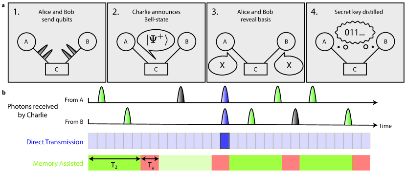
Efficient, long-lived quantum memory nodes are expected to play an essential role in extending the range of quantum communication Briegel et al. (1998), as they enable asynchronous quantum logic operations, such as Bell-state measurements (BSM), between optical photons. For example, the BSM is crucial to MDI-QKD Lo et al. (2012); Braunstein and Pirandola (2012), which is a specific implementation of quantum cryptography illustrated in Fig. 1a. Two remote communicating parties, Alice and Bob, try to agree on a key that is secure against potential eavesdroppers. They each send a randomly chosen photonic qubit encoded in one of two conjugate bases (X or Y) across a lossy channel to an untrusted central node (Charlie), who is asked to perform a BSM and report the result over an authenticated public channel. After a number of iterations, Alice and Bob publicly reveal their choice of bases to obtain a sifted key from the cases when they used a compatible basis. A provably secure key can subsequently be extracted provided the BSM error rate is low enough. While MDI-QKD can be implemented with just linear optics and single photon detectors, the BSM in this “direct-transmission” approach is only successful when photons from Alice and Bob arrive simultaneously. Thus, when Alice and Bob are separated by a lossy fiber with a total transmission probability , Charlie measures photon coincidences with probability also limited by , leading to a fundamental bound Pirandola et al. (2017) on the maximum possible secret key rate of bits per channel use for an unbiased basis choice Gisin et al. (2002). While linear optical techniques to circumvent this bound are now being actively explored Minder et al. (2019), they offer only limited improvement and cannot be scaled beyond a single intermediate node. Alternatively, this bound can be broken using a quantum memory node at Charlie’s location. In this approach, illustrated in Fig. 1b, the state of Alice’s photon is efficiently stored in the heralded memory while awaiting receipt of Bob’s photon over the lossy channel. Once the second photon arrives, a BSM between Alice’s and Bob’s qubits yields a secret key rate that for an ideal memory scales as Panayi et al. (2014), potentially leading to substantial improvement over direct transmission. Beyond this specific protocol, memory-based asynchronous Bell-state measurements are central for the realization of scalable quantum repeaters Briegel et al. (1998) with multiple intermediate nodes.
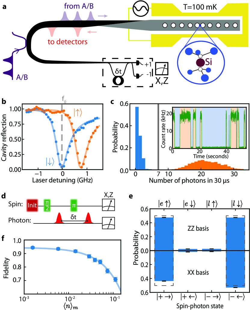
This Letter describes the operation of such a quantum memory node, enabling MDI-QKD at rates that exceed those of an ideal system based on linear optics. Our realization is based on a single silicon-vacancy (SiV) color-center integrated inside a diamond nanophotonic cavity Evans et al. (2018); Burek et al. (2017); Nguyen et al. (2019a) (Fig. 2a). Its key figure-of-merit, the cooperativity Reiserer and Rempe (2015), describes the ratio of the interaction rate with individual cavity photons compared to all dissipation rates. A low mode volume (), high quality factor (), and nanoscale positioning of SiV centers enable an exceptional . Cavity photons are critically coupled to a waveguide and adiabatically transferred into a single-mode optical fiber Burek et al. (2017) that is routed to superconducting nanowire single-photon detectors, yielding a full system detection efficiency of about SOM . The device is placed inside a dilution refrigerator, resulting in electronic spin quantum memory time Nguyen et al. (2019a).
The operating principle of the SiV-cavity based spin-photon interface is illustrated in Fig. 2. Spin dependent modulation of the cavity reflection at incident probe frequency (Fig. 2b) results in the direct observation of electron spin quantum jumps (Fig. 2c, inset), enabling nondestructive single-shot readout of the spin state (Fig. 2c) in with fidelity . Coherent control of the SiV spin qubit ( ) is accomplished using microwave fields delivered via an on-chip gold coplanar waveguide Nguyen et al. (2019a). We utilize both optical readout and microwave control to perform projective feedback-based initialization of the SiV spin into the state with a fidelity of . Spin-dependent cavity reflection also enables quantum logic operations between an incoming photonic time-bin qubit and the spin memory Nguyen et al. (2019a); Duan and Kimble (2004). We characterize this by using the protocol illustrated in Fig. 2d to generate the spin-photon entangled state conditioned on successful reflection of an incoming single photon with overall heralding efficiency SOM . Here, and denote the presence of a photon in an early or late time-bin separated by respectively. We characterize the entangled state by performing measurements in the joint spin-photon ZZ and XX bases (Fig. 2e), implementing local operations on the reflected photonic qubit with a time-delay interferometer (Fig. 2a, dashed box). By lowering the average number of photons incident on the device during the SiV memory time, we reduce the possibility that an additional photon reaches the cavity without being subsequently detected, enabling high spin-photon gate fidelities for small (Fig. 2f). For we measure a lower bound on the fidelity Nguyen et al. (2019a) of the spin-photon entangled state of , primarily limited by residual reflections from the state.
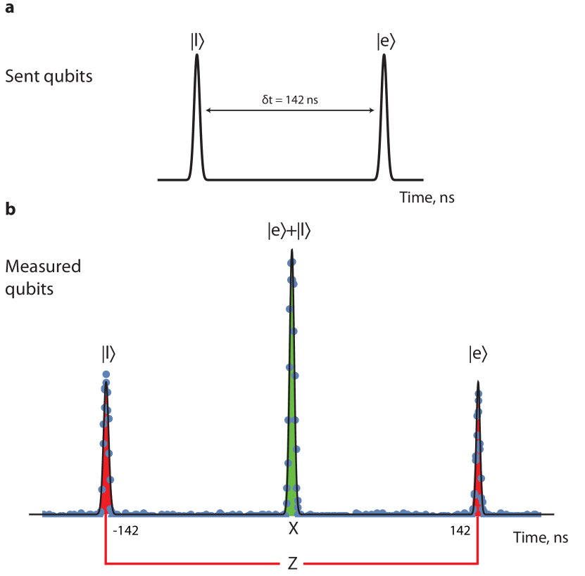
This spin-photon logic gate can be directly used to herald the storage of an incoming photonic qubit by interferometrically measuring the reflected photon in the X basis Nguyen et al. (2019a). To implement memory-assisted MDI-QKD, we extend this protocol to accommodate a total of photonic qubit time-bins within a single initialization of the memory (Fig. 3a). Each individual time-bin qubit is encoded in the relative amplitudes and phases of a pair of neighboring pulses separated by . Detection of a reflected photon heralds the arrival of the photonic qubit formed by the two interfering pulses without revealing its state Nguyen et al. (2019a). Two such heralding events, combined with subsequent spin-state readout in the basis, constitute a successful BSM on the incident photons. This can be understood without loss of generality by restricting input photonic states to be encoded in the relative phase between neighboring pulses with equal amplitude: (Fig. 3b). Detection of the first reflected photon in the X basis teleports its quantum state onto the spin, resulting in the state , where depending on which detector registers the photon Nguyen et al. (2019a). Detection of a second photon at a later time within the electron spin results in the spin state . The phase of this spin state depends only on the sum of the incoming phases and the product of their detection outcomes, but not the individual phases themselves. As a result, if the photons were sent with phases that meet the condition , a final measurement of the spin in the basis completes an asynchronous photon-photon BSM, distinguishing two of the four Bell-states based on the total parity SOM .
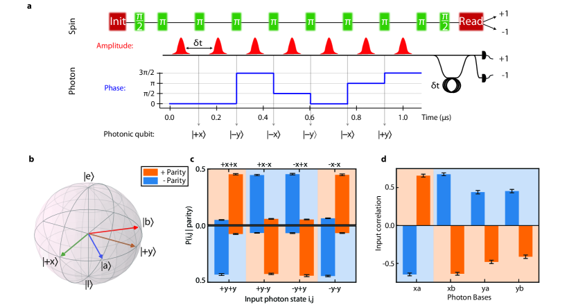
This approach can be directly applied to generate a secure key within the MDI-QKD protocol illustrated in Fig. 1a. We analyze the system performance by characterizing the overall quantum-bit error rate (QBER) Gisin et al. (2002); Lo et al. (2012) for photonic qubits per memory initialization. We use several random bit strings of incoming photons from and observe strong correlations between the resulting BSM outcome and the initial combination of input qubits for both bases (Fig. 3c). Using this method, we estimate the average QBER to be for all combinations of random bit strings measured, significantly below the limit of providing security against individual attacks Gisin et al. (2002). This value is affected by technical imperfections in the preparation of random strings of photonic qubits. We find specific periodic patterns of photonic qubits to be less prone to these effects, resulting in a QBER as low as , which falls within the threshold for unconditional security of Shor and Preskill (2000) with a confidence level of SOM . We further verify security by testing the Bell-CHSH inequality Hensen et al. (2015) using input states from four different bases, each separated by an angle of SOM . We find that the correlations between input photons (Fig. 3d) violate the Bell-CHSH inequality , observing and for positive and negative BSM parity results respectively. This result demonstrates that this device can be used for fundamentally secure quantum communication Gisin et al. (2002).
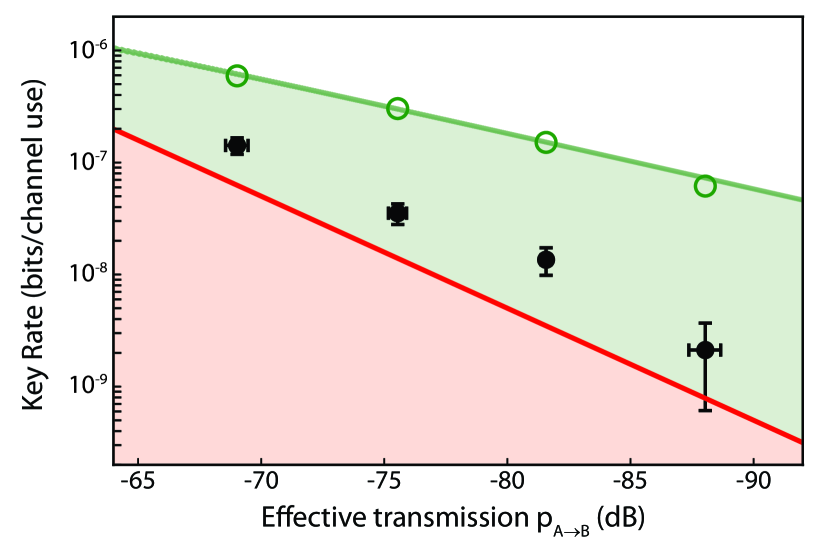
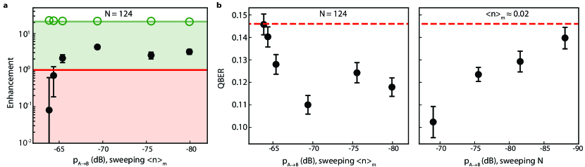
Finally, we benchmark the performance of memory-assisted QKD. For each experiment, we model an effective channel loss by considering the mean photon number incident on the device per photonic qubit. Assuming that Alice and Bob emit roughly one photon per qubit, this yields an effective channel transmission probability , resulting in the maximal secret key rate per channel use for direct transmission MDI-QKD Lo et al. (2012), given by the red line in Fig. 4. We emphasize that this is a theoretical upper bound on linear optics based MDI-QKD, assuming ideal sources and detectors and balanced basis choices. The measured sifted key rates of the memory-based device are plotted as open circles in Fig. 4. Due to the high overall heralding efficiency and the large number of photonic qubits per memory time (up to ), the memory-assisted sifted key rate exceeds the capability of direct-transmission MDI-QKD by a factor of at an effective channel loss of about .
In practice, errors introduced by the quantum memory node could leak information to the environment, reducing the security of the sifted key Shor and Preskill (2000). The fraction of secure bits that can be extracted from a sifted key with finite QBER using conventional error correction and privacy amplification techniques rapidly diminishes Gisin et al. (2002) as the QBER approaches . For each value of the effective channel loss, we estimate the QBER and use it to compute , enabling extraction of distilled secure key rates , plotted in black in Fig. 4. Even after error-correction, we find that the memory-assisted secret key rate outperforms the ideal limit for the corresponding direct-transmission implementation of MDI-QKD by a factor of up to ( systematic uncertainty, for ). We further find that this rate also exceeds the fundamental bound on repeaterless communication Pirandola et al. (2017) with a statistical confidence level of ( systematic uncertainty SOM ). Despite experimental overhead time associated with operating the quantum memory node ( in Fig. 1b), the performance of the memory assisted BSM (for ) enables MDI-QKD that is competitive with an ideal unassisted system running at a average clock rate SOM .
These experiments demonstrate the viability of memory-enhanced quantum communication and represent a crucial step towards realizing functional quantum repeaters. Several important technical improvements will be necessary to apply this advance for practical quantum communication. First, this protocol must be implemented using truly independent, distant communicating parties. Additionally, frequency conversion from telecommunications wavelengths, as well as low-loss optical elements used for routing photons to and from the memory node, will need to be incorporated. Finally, rapid generation of provably secure keys will require implementation of decoy-state protocols Lo et al. (2005a), biased bases Lo et al. (2005b), and finite-key analyses Curty et al. (2014), all compatible with the present approach. With these improvements, our approach is well-suited for deployment in real-world settings. It does not require phase stabilization of long-distance links and operates efficiently in the relevant regime of , corresponding to about of telecommunications fiber. Additionally, a single device can be used at the center of a star network topology Biham et al. (1996), enabling quantum communication between several parties beyond the metropolitan scale. Furthermore, the present approach can be extended along several directions. The use of long-lived nuclear spin qubits could eliminate the need to operate at low total and would provide longer storage times, potentially enabling hundred-fold enhancement of BSM success rates Kalb et al. (2017); Nguyen et al. (2019a). Recently implemented strain-tuning capabilities Machielse et al. (2019) should allow for operation of many quantum nodes at a common network frequency. Unlike linear-optics based alternatives Minder et al. (2019), the approach presented here can be extended to implement the full repeater protocol, enabling a polynomial scaling of the communication rate with distance Briegel et al. (1998). Finally, the demonstrated multi-photon gate operations can also be adapted to engineer large cluster-states of entangled photonsRaussendorf and Briegel (2001), which can be utilized for rapid quantum communication Borregaard et al. (2019). Implementation of these techniques could enable the realization and applications of scalable quantum networks Kimble (2008) beyond QKD, ranging from non-local quantum metrology Khabiboulline et al. (2019) to modular quantum computing architectures Monroe et al. (2014).
I Acknowledgments
Acknowledgements.
We thank Pavel Stroganov, Kristiaan de Greve, Johannes Borregaard, Eric Bersin, Benjamin Dixon, and Neil Sinclair for discussions, Vikas Anant from PhotonSpot for providing SNSPDs, and Jim MacArthur for assistance with electronics. This work was supported by the NSF, CUA, DoD/ARO DURIP, AFOSR MURI, ONR MURI, ARL, and a Vannevar Bush Faculty Fellowship. Devices were fabricated at Harvard CNS, NSF award no. 1541959. M. K. B. and D. S. L. acknowledge support from an NDSEG Fellowship. R. R. acknowledges support from the Alexander von Humbolt Foundation. B. M. and E. N. K. acknowledge support from an NSF GRFP.References
- Kimble (2008) H. J. Kimble, The quantum internet, Nature 453, 1023 (2008).
- Bennett and Brassard (1984) C. H. Bennett and G. Brassard, Quantum cryptography: Public key distribution and coin tossing, Proceedings of the IEEE International Conference on Computers, Systems and Signal Processing 175, 8 (1984).
- Shor and Preskill (2000) P. W. Shor and J. Preskill, Simple proof of security of the BB84 quantum key distribution protocol, Physical Review Letters 85, 441 (2000).
- Wootters and Zurek (1982) W. K. Wootters and W. H. Zurek, A single quantum cannot be cloned, Nature 299, 802 (1982).
- Dieks (1982) D. Dieks, Communication by EPR devices, Physics Letters A 92, 271 (1982).
- Gisin et al. (2002) N. Gisin, G. Ribordy, W. Tittel, and H. Zbinden, Quantum cryptography, Reviews of Modern Physics 74, 145 (2002).
- Boaron et al. (2018) A. Boaron, G. Boso, D. Rusca, C. Vulliez, C. Autebert, M. Caloz, M. Perrenoud, G. Gras, F. Bussières, M. J. Li, D. Nolan, A. Martin, and H. Zbinden, Secure Quantum Key Distribution over 421 km of Optical Fiber, Physical Review Letters 121, 1 (2018).
- Zhang et al. (2018) Q. Zhang, F. Xu, Y.-A. Chen, C.-Z. Peng, and J.-W. Pan, Large scale quantum key distribution: challenges and solutions [Invited], Optics Express 26, 24260 (2018).
- Pirandola et al. (2019) S. Pirandola, U. L. Andersen, L. Banchi, M. Berta, D. Bunandar, R. Colbeck, D. Englund, T. Gehring, C. Lupo, C. Ottaviani, J. Pereira, M. Razavi, J. S. Shaari, M. Tomamichel, V. C. Usenko, G. Vallone, P. Villoresi, and P. Wallden, Advances in Quantum Cryptography, arXiv:1906.01645 (2019).
- Pirandola et al. (2017) S. Pirandola, R. Laurenza, C. Ottaviani, and L. Banchi, Fundamental limits of repeaterless quantum communications, Nature Communications 8, 15043 (2017).
- Briegel et al. (1998) H.-J. Briegel, W. Dür, J. I. Cirac, and P. Zoller, Quantum Repeaters: The Role of Imperfect Local Operations in Quantum Communication, Physical Review Letters 81, 5932 (1998).
- Chou et al. (2007) C.-W. Chou, J. Laurat, H. Deng, K. S. Choi, H. de Riedmatten, D. Felinto, and H. J. Kimble, Functional Quantum Nodes for Entanglement Distribution over Scalable Quantum Networks, Science 316, 1316 LP (2007).
- Yuan et al. (2008) Z.-S. Yuan, Y.-A. Chen, B. Zhao, S. Chen, J. Schmiedmayer, and J.-W. Pan, Experimental demonstration of a BDCZ quantum repeater node, Nature 454, 1098 (2008).
- Gao et al. (2012) W. B. Gao, P. Fallahi, E. Togan, J. Miguel-Sanchez, and A. Imamoglu, Observation of entanglement between a quantum dot spin and a single photon, Nature 491, 426 (2012).
- Reiserer and Rempe (2015) A. Reiserer and G. Rempe, Cavity-based quantum networks with single atoms and optical photons, Reviews of Modern Physics 87, 1379 (2015).
- Hensen et al. (2015) B. Hensen, H. Bernien, A. E. Dréau, A. Reiserer, N. Kalb, M. S. Blok, J. Ruitenberg, R. F. L. Vermeulen, R. N. Schouten, C. Abellán, W. Amaya, V. Pruneri, M. W. Mitchell, M. Markham, D. J. Twitchen, D. Elkouss, S. Wehner, T. H. Taminiau, and R. Hanson, Loophole-free Bell inequality violation using electron spins separated by 1.3 kilometres, Nature 526, 682 (2015).
- Kalb et al. (2017) N. Kalb, A. A. Reiserer, P. C. Humphreys, J. J. W. Bakermans, S. J. Kamerling, N. H. Nickerson, S. C. Benjamin, D. J. Twitchen, M. Markham, and R. Hanson, Entanglement distillation between solid-state quantum network nodes, Science 356, 928 LP (2017).
- Evans et al. (2018) R. E. Evans, M. K. Bhaskar, D. D. Sukachev, C. T. Nguyen, A. Sipahigil, M. J. Burek, B. Machielse, G. H. Zhang, A. S. Zibrov, E. Bielejec, H. Park, M. Lončar, and M. D. Lukin, Photon-mediated interactions between quantum emitters in a diamond nanocavity, Science 362, 662 LP (2018).
- Burek et al. (2017) M. J. Burek, C. Meuwly, R. E. Evans, M. K. Bhaskar, A. Sipahigil, S. Meesala, B. Machielse, D. D. Sukachev, C. T. Nguyen, J. L. Pacheco, E. Bielejec, M. D. Lukin, and M. Lončar, Fiber-Coupled Diamond Quantum Nanophotonic Interface, Physical Review Applied 8, 24026 (2017).
- Nguyen et al. (2019a) C. T. Nguyen, D. D. Sukachev, M. K. Bhaskar, B. Machielse, D. S. Levonian, E. N. Knall, P. Stroganov, R. Riedinger, H. Park, M. Lončar, and M. D. Lukin, Quantum network nodes based on diamond qubits with an efficient nanophotonic interface, arXiv:1907.13199 (2019a).
- Khabiboulline et al. (2019) E. T. Khabiboulline, J. Borregaard, K. De Greve, and M. D. Lukin, Optical interferometry with quantum networks, Phys. Rev. Lett. 123, 070504 (2019).
- Monroe et al. (2014) C. Monroe, R. Raussendorf, A. Ruthven, K. R. Brown, P. Maunz, L.-M. Duan, and J. Kim, Large-scale modular quantum-computer architecture with atomic memory and photonic interconnects, Physical Review A 89, 22317 (2014).
- Lo et al. (2012) H.-K. Lo, M. Curty, and B. Qi, Measurement-Device-Independent Quantum Key Distribution, Physical Review Letters 108, 130503 (2012).
- Braunstein and Pirandola (2012) S. L. Braunstein and S. Pirandola, Side-Channel-Free Quantum Key Distribution, Physical Review Letters 108, 130502 (2012).
- Minder et al. (2019) M. Minder, M. Pittaluga, G. L. Roberts, M. Lucamarini, J. F. Dynes, Z. L. Yuan, and A. J. Shields, Experimental quantum key distribution beyond the repeaterless secret key capacity, Nature Photonics 13, 334 (2019).
- Panayi et al. (2014) C. Panayi, M. Razavi, X. Ma, and N. Lütkenhaus, Memory-assisted measurement-device-independent quantum key distribution, New Journal of Physics 16, 43005 (2014).
- (27) See supplementary material following the main text.
- Duan and Kimble (2004) L.-M. Duan and H. J. Kimble, Scalable Photonic Quantum Computation through Cavity-Assisted Interactions, Physical Review Letters 92, 127902 (2004).
- Lo et al. (2005a) H.-K. Lo, X. Ma, and K. Chen, Decoy State Quantum Key Distribution, Physical Review Letters 94, 230504 (2005a).
- Lo et al. (2005b) H.-K. Lo, H. F. Chau, and M. Ardehali, Efficient Quantum Key Distribution Scheme and a Proof of Its Unconditional Security, Journal of Cryptology 18, 133 (2005b).
- Curty et al. (2014) M. Curty, F. Xu, W. Cui, C. C. W. Lim, K. Tamaki, and H.-K. Lo, Finite-key analysis for measurement-device-independent quantum key distribution, Nature Communications 5, 3732 (2014).
- Biham et al. (1996) E. Biham, B. Huttner, and T. Mor, Quantum cryptographic network based on quantum memories, Physical Review A 54, 2651 (1996).
- Machielse et al. (2019) B. Machielse, S. Bogdanovic, S. Meesala, S. Gauthier, M. J. Burek, G. Joe, M. Chalupnik, Y. I. Sohn, J. Holzgrafe, R. E. Evans, C. Chia, H. Atikian, M. K. Bhaskar, D. D. Sukachev, L. Shao, S. Maity, M. D. Lukin, and M. Lončar, Quantum Interference of Electromechanically Stabilized Emitters in Nanophotonic Devices, Physical Review X 9, 31022 (2019).
- Raussendorf and Briegel (2001) R. Raussendorf and H. J. Briegel, A One-Way Quantum Computer, Physical Review Letters 86, 5188 (2001).
- Borregaard et al. (2019) J. Borregaard, H. Pichler, T. Schöder, M. D. Lukin, P. Lodahl, and A. S. Sørensen, One-way quantum repeater based on near-deterministic photon-emitter interfaces, arXiv:1907.05101 (2019).
- Burek et al. (2014) M. J. Burek, Y. Chu, M. S. Z. Liddy, P. Patel, J. Rochman, S. Meesala, W. Hong, Q. Quan, M. D. Lukin, and M. Lončar, High quality-factor optical nanocavities in bulk single-crystal diamond, Nature Communications 5, 5718 (2014).
- Atikian et al. (2017) H. A. Atikian, P. Latawiec, M. J. Burek, Y.-I. Sohn, S. Meesala, N. Gravel, A. B. Kouki, and M. Lončar, Freestanding nanostructures via reactive ion beam angled etching, APL Photonics 2, 51301 (2017).
- Nguyen et al. (2019b) C. T. Nguyen, D. D. Sukachev, M. K. Bhaskar, B. Machielse, D. S. Levonian, E. N. Knall, P. Stroganov, C. Chia, M. J. Burek, R. Riedinger, H. Park, M. Lončar, and M. D. Lukin, An integrated nanophotonic quantum register based on silicon-vacancy spins in diamond, arXiv:1907.13200 (2019b).
- de Riedmatten et al. (2004) H. de Riedmatten, I. Marcikic, V. Scarani, W. Tittel, H. Zbinden, and N. Gisin, Tailoring photonic entanglement in high-dimensional Hilbert spaces, Physical Review A 69, 50304 (2004).
- Sasaki et al. (2014) T. Sasaki, Y. Yamamoto, and M. Koashi, Practical quantum key distribution protocol without monitoring signal disturbance, Nature 509, 475 (2014).
- Kalb et al. (2015) N. Kalb, A. Reiserer, S. Ritter, and G. Rempe, Heralded Storage of a Photonic Quantum Bit in a Single Atom, Physical Review Letters 114, 220501 (2015).
- Clauser et al. (1969) J. F. Clauser, M. A. Horne, A. Shimony, and R. A. Holt, Proposed Experiment to Test Local Hidden-Variable Theories, Physical Review Letters 23, 880 (1969).
Supplementary Material
II Experimental setup
Experimental setup and device fabrication Burek et al. (2014, 2017); Machielse et al. (2019); Atikian et al. (2017) for millikelvin nanophotonic cavity QED experiments with SiV centers are thoroughly described in a separate publication Nguyen et al. (2019b). We perform all measurements in a dilution refrigerator (DR, BlueFors BF-LD250) with a base temperature of 20 mK. The DR is equipped with a superconducting vector magnet (American Magnets Inc. 6-1-1 T), a home-built free-space wide-field microscope with a cryogenic objective (Attocube LT-APO-VISIR), piezo positioners (Attocube ANPx101 and ANPx311 series), and fiber and MW feedthroughs. Tuning of the nanocavity resonance is performed using a gas condensation technique Evans et al. (2018). The SiV-cavity system is optically interrogated through the fiber network without any free-space optics Nguyen et al. (2019a). The operating temperature of the memory node during the BSM measurements was 100-300 mK.
II.1 Experimental implementation of asynchronous BSM
An asynchronous BSM (Fig. 3a) relies on (1) precise timing of the arrival of optical pulses (corresponding to photonic qubits de Riedmatten et al. (2004); Sasaki et al. (2014) from Alice and Bob) with microwave control pulses on the quantum memory and (2) interferometrically stable rotations on reflected time-bin qubits for successful heralding. In order to accomplish (1), all equipment used for generation of microwave and optical fields is synchronized by a single device (National Instriuments HSDIO, Fig. S1a) with programming described in Table S1-2.
In order to accomplish (2), we use a single, narrow linewidth ( ) Ti:Sapphire laser (M Squared SolsTiS-2000-PSX-XF, Fig. S1b) both for generating photonic qubits and locking the time-delay interferometer (TDI) used to herald their arrival. In the experiment, photonic qubits are reflected from the device, sent into the TDI, and detected on superconducting nanowire single photon detectors (SNSPD, Photon Spot). All detected photons are processed digitally on a field-programmable gate array (FPGA, Fig. S1a), and the arrival times of these heralding signals are recorded on a time-tagger (TT, Fig. S1a), and constitute one bit of information of the BSM ( or ). At the end of the experiment, a pulse from the readout path is reflected off the device, and photons are counted in order to determine the spin state () depending on the threshold shown in Fig. 2c.
| Step | Process | Duration | Proceed to |
|---|---|---|---|
| 1 | Lock time-delay interferometer | 2 | |
| 2 | Readout SiV | If status LOW: 4, else: 3 | |
| 3 | Apply microwave pulse | 2 | |
| 4 | Run main experiment script | 1 |
| Step | Process | Duration | Proceed to |
|---|---|---|---|
| 1 | Run sequence in Fig. 3a for a given | 2 | |
| 2 | Readout SiV + report readout to TT | If status LOW: 1, else: 3 | |
| 3 | Apply microwave pulse | 4 | |
| 4 | Readout SiV | If status LOW: 3, else: 1 |
To minimize thermal drift of the TDI, it is mounted to a thermally weighted aluminum breadboard, placed in a polyurethane foam-lined and sand filled briefcase, and secured with glue to ensure passive stability on the minute timescale. We halt the experiment and actively lock the interferometer to the sensitive Y-quadrature every by changing the length of the roughly long () delay line with a cylindrical piezo. In order to use the TDI for X-measurements of the reflected qubits, we apply a frequency shift of using the qubit AOM, which is of the free-spectral range of the TDI. Since the nanophotonic cavity, the TDI, and the SNSPDs are all polarization sensitive, we use various fiber-based polarization controllers (Fig. S1b). All fibers in the network are covered with aluminum foil to prevent thermal polarization drifts. This results in an interference visibility of the TDI of that is stable for several days without any intervention with lab temperature and humidity variations of C and respectively.
In order to achieve high-fidelity operations we have to ensure that the laser frequency (which is not locked) is resonant with the SiV frequency (which is subject to the spectral diffusion Nguyen et al. (2019b)). To do that we implement a so-called preselection procedure, described in Table S1-2 and Fig. S1a. First, the SiV spin state is initialized by performing a projective measurement and applying microwave feedback. During each projective readout, the reflected counts are compared with two thresholds: a “readout” threshold of photons (used only to record ), and a “status” threshold of photons. The status trigger is used to prevent the experiment from running in cases when the laser is no longer on resonance with , or if the SiV has ionized to an optically inactive charge state. The duty cycle of the status trigger is externally monitored and is used to temporarily abort the experiment and run an automated re-lock procedure that locates and sets the laser to the new frequency , reinitailizing the SiV charge state with a laser pulse if nececssary. This protocol enables fully automated operation at high fidelities (low QBER) for several days without human intervention.
II.2 Calibration of fiber network
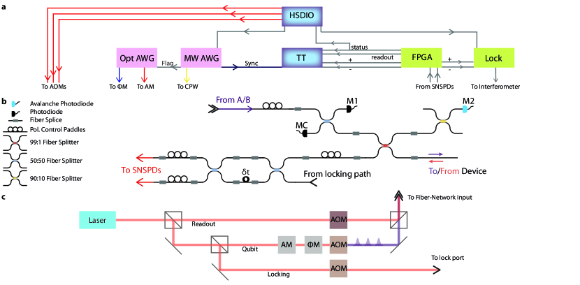
The schematic of the fiber-network used to deliver optical pulses to and collect reflected photons from the nanophotonic memory device is shown in Fig. S1b. Photons are routed through the lossy () port of a 99:1 fiber beamsplitter (FBS) to the nanophotonic device. We note that for practical implementation of memory-assisted quantum communication, an efficient optical switch or circulator should be used instead. In this experiment, since we focus on benchmarking the performance of the memory device itself, the loss introduced by this beamsplitter is incorporated into the estimated channel loss. Reflected photons are collected and routed back through the efficient () port of the FBS and are sent to the TDI in the heralding setup.
The outputs of the TDI are sent back into the dilution refrigerator and directly coupled to superconducting nanowire single-photon detectors (SNSPDs, PhotonSpot), which are mounted at the 1K stage and are coated with dielectrics to optimize detection efficiency exactly at . To estimate the quantum efficiency (QE) of the detectors we compare the performance of the SNSPDs to the specifications of calibrated conventional avalanche photodiodes single-photon counters (Laser Components COUNT-10C-FC). The estimated QEs of the SNSPDs with this method are as close to unity as we can verify. Additionally, we measure reflection from the fiber-SNSPD interface, which typically is the dominant contribution to the reduction of QE in these devices. Thus we assume the lower bound of the QE of the SNSPDs to be for the rest of this section. Of course, this estimation is subject to additional systematic errors. However, the actual QE of these detectors would be a common factor (and thus drop out) in a comparison between any two physical quantum communication systems.
The total heralding efficiency of the memory node is an important parameter since it directly affects the performance of the BSM for quantum communication experiments. Here we use 2 different approaches to estimate the overall heralding efficiency . We first measure the most dominant loss, which arises from the average reflectivity of the critically coupled nanophotonic cavity (Fig. 2b). While the state is highly reflecting (), the state reflects only of incident photons, leading to an average device reflectivity of .
In method (1), we compare the input power photodiode M1 with that of photodiode MC. This estimates a lower-bound on the tapered-fiber diamond waveguide coupling efficiency of . This error bar arises from uncertainty due to photodiode noise and does not include systematic photodiode calibration uncertainty. However, we note that if the tapered fiber is replaced by a silver-coated fiber-based retroreflector, this calibration technique extracts a coupling efficiency of , which is consistent with the expected reflectivity from such a retroreflector. We independently calibrate the efficiency through the 99:1 fiber beamsplitter and the TDI to be . This gives us our first estimate on the overall heralding efficiency .
In method (2), during the experiment we compare the reflected counts from the highly-reflecting () spin-state measured on the SNSPDs with the counts on an avalanche photodiode single photon counting module (M2 in Fig. S1b) which has a calibrated efficiency of relative to the SNSPDs. From this measurement, we estimate an overall efficiency of fiber-diamond coupling, as well as transmission through all relevant splices and beamsplitters of . This error bar arises from shot noise on the single photon detectors. Overall, this gives us a consistent estimate of .
For values cited in the main text and data points presented in the figures, we use an average value of the heralding efficiency inferred from the two calibration techniques: . Methods (1) and (2), which each have independent systematic uncertainties associated with imperfect photodetector calibrations, are consistent to within a small residual systematic uncertainty, which is noted in the text where appropriate. We note that this heralding efficiency is consistent with the scaling of spin decoherence with the number of photons at the cavity . An example of this effect is shown in the red point in Fig. S3e.
III Characterization of the nanophotonic quantum memory.
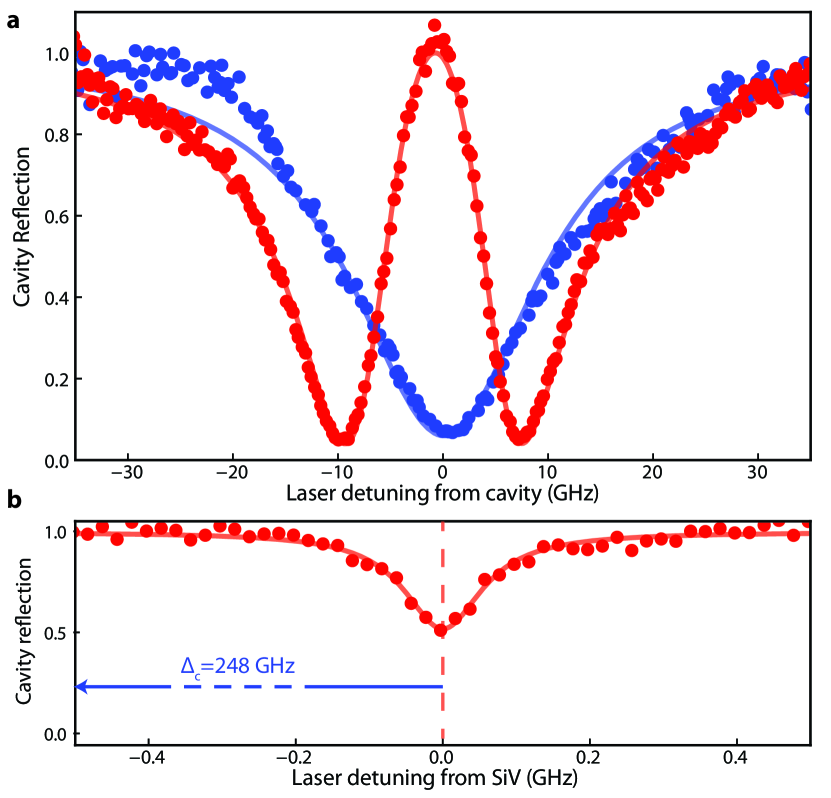
A spectrum of the SiV-cavity system at large detuning (248 GHz) allows us to measure the cavity linewidth GHz, (Fig. S2a, blue curve) and natural SiV linewidth GHz (Fig. S2a, red curve). We find spectral diffusion of the SiV optical frequency to be much smaller than on minute timescales with an excitation photon flux of less than . Next, we estimate the single-photon Rabi frequency, , using the cavity reflection spectrum for zero atom-cavity detuning, shown in red in Fig. S2a. For a resonant atom-cavity system probed in reflection from a single port with cavity-waveguide coupling , the cavity reflection coefficient Reiserer and Rempe (2015) as a function of probe detuning is given by
| (1) |
By fitting using known values of and , we obtain the solid red curve in Fig. S2a which corresponds to a single-photon Rabi frequency , yielding the estimated cooperativity .
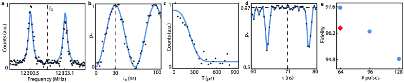
We use resonant MW pulses delivered via an on-chip coplanar waveguide (CWG) to coherently control the quantum memory Nguyen et al. (2019a, b). First, we measure the spectrum of the spin-qubit transition by applying a weak, -long microwave pulse of variable frequency, observing the optically-detected magnetic resonance (ODMR) spectrum presented in Fig. S3a. We note that the spin-qubit transition is split by the presence of a nearby . While coherent control techniques can be employed to utilize the as an additional qubit Nguyen et al. (2019a, b), we do not control or initialize it in this experiment. Instead, we drive the electron spin with strong microwave pulses at a frequency such that both -state-specific transitions are addressed equally. This also mitigates slow spectral diffusion of the microwave transition Nguyen et al. (2019b) of .
After fixing the MW frequency at we vary the length of this drive pulse ( in Fig. S3b) and observe full-contrast Rabi oscillations. We choose a time of in the experiments in the main text, which is a compromise of two factors: (1) it is sufficiently fast such that we can temporally multiplex between and time-bin qubits around each microwave pulse and (2) it is sufficiently weak to minimize heating related effects from high microwave currents in resistive gold CWG.
With known time we measure the coherence time of the SiV spin qubit under an XY8-1 dynamical decoupling sequence to exceed (Fig. S3c). In the main experiment we use decoupling sequences with more pulses. As an example, Fig. S3d shows the population in the state after XY8-8 decoupling sequence (total pulses) as a function of , half of the inter-pulse spacing. For BSM experiments, this inter-pulse spacing, , is fixed and is matched to the time-bin interval . While at some times (e.g. ) there is a loss of coherence due to entanglement with the nearby , at we are decoupled from this and can maintain a high degree of spin coherence. Thus we chose the time-bin spacing to be 142 ns. The spin coherence at is plotted as a function in Fig. S3d, and decreases for large , primarily due to heating related effects Nguyen et al. (2019a).
IV Theoretical description of asynchronous Bell state measurement
Due to the critical coupling of the nanocavity, the memory node only reflects photons when the SiV spin is in the state . The resulting correlations between the spin and the reflected photons can still be used to realize a BSM between two asynchronously arriving photonic time-bin qubits using an adaptation of the well known proposal of Duan and Kimble Duan and Kimble (2004) for entangling a pair of photons incident on an atom-cavity system. As a result of the critical coupling, we only have access to two of the four Bell states at any time, with the inaccessible Bell states corresponding to photons being transmitted through the cavity (and thus lost from the detection path). Depending on whether there was an even or odd number of -pulses on the spin between the arrival of the two heralded photons, we distinguish either the or states (defined below). For the sake of simplicity, we first describe the BSM for the case when the early time bin of Alice’s and Bob’s qubits both arrive after an even number of microwave pulses after its initialization. Thereafter we generalize this result and describe the practical consequences for the MDI-QKD protocol.
The sequence begins with a microwave pulse, preparing the spin in the state . In the absence of a photon at the device, the subsequent microwave -pulses, which follow an XY8-N type pattern, decouple the spin from the environment and at the end of the sequence should preserve the spin state . However, reflection of Alice’s photonic qubit from the device results in the entangled spin-photon state . The full system is in the state
| (2) |
Regardless of the input photon state, there is equal probability to measure the reflected photon to be . Thus, measuring the photon in X basis (through the TDI) does not reveal the initial photon state. After this measurement, the initial state of the photon is teleported onto the spin: , where denotes the detection outcome of the TDI Nguyen et al. (2019a); Kalb et al. (2015). The quantum state of Alice’s photon is now stored in the spin state, which is preserved by the dynamical decoupling sequence.
Reflection of the second photon from Bob results in the spin-photon state . This state now has a phase that depends on the initial states of both photons, enabling the photon-photon BSM measurements described below. Rewriting Bob’s reflected photon in the X basis, the full system is in the state
| (3) |
The second measurement result once again contains no information about the initial state , yet heralds the final spin state as described in the main text. When this state lies along the X axis of the Bloch sphere (), the final result of the X basis measurement on the spin state has a deterministic outcome, dictated by all values of the parameters (known only to Alice and Bob) and (which are known to Charlie, but are completely random). Conversely, all information available to Charlie only contains information on the correlation between the photonic qubits, not on their individual states. The resulting truth table for different input states is given in Table S3. For all input states, there is equal probability of measuring for each individual measurement . However, the overall parity of the three measurements depends on whether or not the input photons were the same, or opposite, for inputs or .
We now address the fact that the BSM distinguishes either between or if there was an even or odd number of microwave pulses between incoming photons respectively. This effect arises because each pulse in the dynamical decoupling sequence toggles an effective frame change: . The impact on this frame change on the BSM can be seen by writing the pairs of Bell states ( and ) in the X and Y bases, where we have
| (4) |
| (5) |
| (6) |
| (7) |
For X basis inputs, as seen by Eq. 4 and 6, switching between and measurements does not affect the inferred correlation between input photons. For Y basis inputs however, this does result in an effective bit flip in the correlation outcome (see Eq. 5 and 7). In practice, Alice and Bob can keep track of each Y photon sent and apply a bit flip accordingly, as long as they have the appropriate timing information about MW pulses applied by Charlie. If Charlie does not give them the appropriate information, this will result in an increased QBER which can be detected.
As a final remark, this scheme also works for pairs of photons that are not both in the X or Y basis but still satisfy the condition . For example, and from Fig. 3b satisfy this condition. In this case, adequate correlations can still be inferred about the input photons, although they were sent in different bases.
| Alice | Bob | Parity | Bell state |
|---|---|---|---|
IV.1 Test of Bell-CHSH inequality
In order to perform a test of the Bell-CHSH inequality Clauser et al. (1969), we send input photons equally distributed from all states (Fig. 3b). We select for cases where two heralding events arise from input photons that are either or apart from one another. Conditioned on the parity outcome of the BSM (), the Bell-CHSH inequality bounds the correlations between input photons as
| (8) |
where the subscripts denote the bases the photons were sent in. The values of each individual term in Eq. 8, denoted as “input correlations,” are plotted in Fig. 3d for positive and negative parity outcomes.
V Analysis of quantum communication experiment
V.1 Estimation of QBER
In order to achieve the lowest QBER, we routinely monitor the status trigger of the pre-selection routine and adjust the TDI. Additionally, we keep track of the timing when the TDI piezo voltage rails. This guarantees that the SiV is always resonant with the photonic qubits and that the TDI performs high-fidelity measurements in X basis. This is implemented in software with a response time of .
For each experiment, we estimate the QBER averaged over all relevant basis combinations. This is equivalent to the QBER when the random bit string has all bases occurring with the same probability, (an unbiased and independent basis choice by Alice and Bob). We first note that the QBER for positive and negative parity announcements are not independent. We illustrate this for the example, that Alice and Bob send photons in the X basis. We denote the probability that Alice sent qubit , Bob sent qubit and the outcome of Charlie’s parity measurement is , conditioned on the detection of a coincidence, as . We find for balanced inputs that with denoting the occurrence of a bit error in the sifted key of Alice and Bob. We thus find for the posterior probability for the average QBER for XX coincidences
| (9) |
Note that this expression is independent of the actual distribution of . Here, the posterior probability is based on the a binomial likelihood function , where denotes the number of occurrences with condition . Finally the posterior probability of the unbiased QBER is . All values presented in the text and figures are maximum likelihood values with bounds given by the confidence interval of integrated posterior probability. Confidence levels towards a specific bound (for example, unconditional security Shor and Preskill (2000)) are given by the integrated posterior probability up to the bound.
To get the ratio of the distilled secret key rate with respect to the sifted key rate by (ideal) error correction and privacy amplification, we use the bounds given by difference in information by Alice and Bob with respect to a potential eavesdropper who performs individual attacks Gisin et al. (2002): . We use the full posterior probability distribution of QBER (which accounts for statistical and systematic uncertainty in our estimate) to compute the error bar on , and correspondingly, the error bars on the extracted secret key rates plotted in Fig. 4.
V.2 Optimal parameters for asynchronous Bell state measurements
We minimize the experimentally extracted QBER for the asynchronous BSM to optimize the performance of the memory node. The first major factor contributing to QBER is the scattering of a third photon that is not detected, due to the finite heralding efficiency . This is shown in Fig. 2f, where the fidelity of the spin-photon entangled state diminishes for . At the same time, we would like to work at the maximum possible in order to maximize the data rate to get enough statistics to extract QBER (and in the quantum communication setting, efficiently generate a key).
To increase the key generation rate per channel use, one can also fit many photonic qubits within each initialization of the memory. In practice, there are 2 physical constraints: (1) the bandwidth of the SiV-photon interface and (2) the coherence time of the memory. We find that one can satisfy (1) at a bandwidth of roughly with no measurable infidelity. For shorter optical pulses ( ns), the spin-photon gate fidelity is reduced. In principle, the SiV-photon bandwidth can be increased by reducing the atom-cavity detuning (here ) at the expense of having to operate at higher magnetic fields where microwave qubit manipulation is not as convenient Nguyen et al. (2019b).
| per channel occupancy | per channel occupancy | per channel use | per channel use | |
|---|---|---|---|---|
| X:Y basis bias | ||||
| Secure key rate | ||||
| confidence level |
Even with just an XY8-1 decoupling sequence (number of pulses ), the coherence time of the SiV is longer than s (Fig. S3c) and can be prolonged to the millisecond range with longer pulse sequences Nguyen et al. (2019a). Unfortunately, to satisfy the bandwidth criteria (1) and to drive both hyperfine transitions (Fig. S3a), we must use short ( long pulses), which cause additional decoherence from ohmic heating Nguyen et al. (2019b) already at (Fig. S3e). Due to this we limit the pulse sequences to a maximum , and only use up to s of the memory time. One solution would be to switch to superconducting microwave delivery. Alternatively, one can use a larger value of to allow the device to cool down in between subsequent pulses Nguyen et al. (2019b) at the expense of having to stabilize a TDI of larger . Working at larger also enables temporal multiplexing by fitting multiple time-bin qubits per free-precession interval. In fact, with , even given constraint (1) and the finite time, we can already fit up to optical pulses per free-precession window, enabling a total number of photonic qubits of up to for only .
In benchmarking the asynchronous BSM for quantum communication, we optimize the parameters and to maximize our enhancement over the direct transmission approach, which is a combination of both increasing and reducing the QBER, since a large QBER results in a small secret key fraction . As described in the main text, the effective loss can be associated with , which is the average number of photons per photonic qubit arriving at the device, and is given straightforwardly by . The most straightforward way to sweep the loss is to keep the experimental sequence the same (fixed ) and vary the overall power, which changes . The results of such a sweep are shown in Fig. S5a, b. For larger (corresponding to lower effective channel losses), the errors associated with scattering an additional photon reduce the performance of the memory device.
Due to these considerations, we work at roughly for experiments in the main text shown in Fig. 3 and 4, below which the performance does not improve significantly. At this value, we obtain BSM successes at a rate of roughly . By fixing and increasing N, we maintain a tolerable BSM success rate while increasing the effective channel loss. Eventually, as demonstrated in Fig. S5c and in the high-loss data point in Fig. 4, effects associated with microwave heating result in errors that again diminish the performance of the memory node for large . As such, we conclude that the optimal performance of our node occurs for and , corresponding to an effective channel loss of between Alice and Bob, which is equivalent to roughly of telecommunications fiber.
We also find that the QBER and thus the performance of the communication link is limited by imperfect preparation of photonic qubits. Photonic qubits are defined by sending arbitrary phase patterns generated by the optical AWG to a phase modulator. For an example of such a pattern, see the blue curve in Fig. 3a. We use an imperfect pulse amplifier with finite bandwidth ( ), and find that the DC component of these waveforms can result in error in photonic qubit preparation on the few level. By using a tailored waveform of phases with smaller (or vanishing) DC component, we can reduce these errors. We run such an experiment during the test of the Bell-CHSH inequality. We find that by evaluating BSM correlations from and inputs during this measurement, we estimate a QBER of .
Finally, we obtain the effective clock-rate of the communication link by measuring the total number of photonic qubits sent over the course of an entire experiment. In practice, we record the number of channel uses, determined by the number of sync triggers recorded (see Fig. S1a) as well as the number of qubits per sync trigger (). We then divide this number by the total experimental time from start to finish ( 1-2 days for most experimental runs), including all experimental downtime used to stabilize the interferometer, readout and initialize the SiV, and compensate for spectral diffusion and ionization. For , we extract a clock rate of . As the secret key rate in this configuration exceeds the conventional limit of by a factor of , it is competitive with a standard MDI-QKD system operating at clock rate.
V.3 Performance of memory-assisted MDI-QKD
A single optical link can provide many channels, for example, by making use of different frequency, polarization, or temporal modes. To account for this, when comparing different systems, data rates can be defined on a per-channel-use basis. In a MDI-QKD setting, full usage of the communication channel between Alice and Bob means that both links from Alice and Bob to Charlie are in use simultaneously. For an asynchronous sequential measurement, typically only half of the channel is used at a time, for example from Alice to Charlie or Bob to Charlie. The other half can in principle be used for a different task when not in use. For example, the unused part of the channel could be routed to a secondary asynchronous BSM device. In our experiment, we can additionally define as a second normalization the rate per channel “occupancy”, which accounts for the fact that only half the channel is used at any given time. The rate per channel occupancy is therefore half the rate per full channel use. For comparison, we typically operate at channel use and channel occupancy.
To characterize the optimal performance of the asynchronous Bell state measurement device, we operate it in the optimal regime determined above (, ). We note that the enhancement in the sifted key rate over direct transmission MDI-QKD is given by
| (10) |
and is independent of for a fixed number of microwave pulses and optical pulses per microwave pulse and thus fixed . For low , three photon events become negligible and therefore QBER saturates, such that the enhancement in the secret key rate saturates as well (Fig. S5a). We can therefore combine all data sets with fixed below to characterize the average QBER of (Fig. 3c). The key rates cited in the main text relate to a data set in this series (), with a QBER of . A summary of key rates calculated on a per-channel use and per-channel occupancy basis, as well as comparisons of performance to ideal MDI-QKD and repeaterless bounds Pirandola et al. (2017) are given in Table S4.
Furthermore, we extrapolate the performance of our memory node to include biased input bases from Alice and Bob. This technique enables a reduction of channel uses where Alice and Bob send photons in different bases, but is still compatible with secure key distribution Lo et al. (2005b), allowing for enhanced secret key rates by at most a factor of . The extrapolated performance of our node for a bias of 99:1 is also displayed in Table S4, as well as comparisons to the relevant bounds. We note that basis biasing does not affect the performance when comparing to the equivalent MDI-QKD experiment, which is limited by in the unbiased case and in the biased case. However, using biased input bases does make the performance of the memory-assisted approach more competitive with the fixed repeaterless bound Pirandola et al. (2017) of .