Mechanism of generation of a Josephson phase shift by an Abrikosov vortex
Abstract
Abrikosov vortex contains magnetic field and circulating currents that decay at a short range nm. However, the vortex can induce a long range Josephson phase shift at distances m. The mechanism of this puzzling phenomenon is not clearly understood. Here we present a systematic study of vortex-induced phase shift in planar Josephson junctions. We make two key observations: (i) The cutoff effect: although vortex-induce phase shift is a long-range phenomenon, it is terminated by the junction and does not persists beyond it. (ii) A crossover from linear to superlinear dependence of the phase shift on the vortex polar angle occurs upon approaching of the vortex to the junction. The crossover occurs at a distance comparable with the penetration depth. This, together with theoretical and numerical analysis of the problem, allows unambiguous identification of two distinct and independent mechanisms. The short range mechanism is due to circulating vortex currents inside superconducting electrodes without involvement of magnetic field. The long range mechanism is due to stray magnetic fields outside electrodes without circulating vortex currents. We argue that understanding of controlling parameters of vortex-induced Josephson phase shift can be used for development of compact and fast electronic devices with low dissipation power.
pacs:
74.72.Hs, 74.78.Fk, 74.50.+r, 85.25.CpI I. Introduction
Josephson electronics operates with the quantum-mechanical phase difference between two superconducting electrodes. In conventional Josephson junctions the phase difference is zero in the absence of applied current and is spatially independent in the absence of external magnetic field. It is anticipated that unconventional junctions either with a fixed phase shift (-junctions), or with an in-built spatial phase variation along the junction ( junctions) may provide additional functionality in Josephson electronics Blatter_2001 ; Ortlepp_2006 ; Feofanov_2010 ; Soloviev_2017 . For example, they can operate as autonomous and persistent phase batteries - one of key elements of quantum Blatter_2001 ; Martinis_2008 ; Gershenson_2009 ; Mooij_2002 ; Wulf_2006 ; Lukens_2007 ; Mooij_2009 ; Semba_2010 ; Mooij_2011 ; Schwarz_2013 ; Deng_2015 and digital Josephson electronics Ortlepp_2006 ; Balashov_2007 ; Dimov_2008 ; Feofanov_2010 . Such junctions can be also used for development of novel types of cryogenic memory Goldobin_2013 ; Zdravkov_2013 ; Dresselhaus_2014 ; Golod_2015 ; Bakurskiy_2016 ; Birge_2018 . The -phase shift is most commonly needed, e.g., for bringing the flux-qubit to the degeneracy point Blatter_2001 ; Martinis_2008 ; Gershenson_2009 ; Mooij_2002 , for realization of complementary digital Josephson electronics Ortlepp_2006 ; Balashov_2007 ; Dimov_2008 ; Feofanov_2010 and for maximum distinction between 0 and 1 state in a memory cell Golod_2015 .
Several ways of making and junctions are known. The spatial phase variation within the junction can be introduced by inhomogeneity, e.g. uneven distribution of critical or bias current, which will cause the self-field effect Geshkenbein_1992 ; Krasnov_1997 ; Gaber_2005 ; Linder_2013 ; Golod_2019 and affect dynamics of Josephson vortices Geshkenbein_1992 ; Krasnov_1997 ; Chesca_2017 . Junctions with a fixed phase can be realized using hybrid Superconductor/Ferromagnet (S/F) structures Ryazanov_2001 ; Aprili_2002 ; Calemczuk_2004 and the unconventional sign-reversal order parameter -wave Ortlepp_2006 ; VanHarlingen_1995 ; Tsuei_2000 or Ota_2009 ; Linder_2009 ; Koshelev_2012 ; Kalenuyk_2018 . Also -junctions with arbitrary phase can be realized using inhomogeneous S/F junction Koshelev_2003 ; Goldobin_2012 , or junctions with a strong spin-orbit coupling Bergeret_2015 . The above mentioned phase-shifted junctions are either persistent but not tunable (e.g. SFS junctions and junctions with sign-reversal order parameter), or tunable but not persistent (e.g. junctions based on uneven current injection Gaber_2005 ).
An Abrikosov vortex (AV), having a phase rotation, can induce a phase shift in a nearby Josephson junction (JJ) Golod_2010 ; Gurevich_1994 ; Aslamazov_1984 ; Clem_2011 ; Kogan2014 ; Mironov_2017 . The vortex-induced phase shift depends on the distance and geometry Golod_2010 ; Clem_2011 . Since vortices can be easily and controllably manipulated (displaced, introduced or removed) by magnetic field Golod_2010 ; Milosevic_2009 , current Golod_2015 ; Finnemore_1994 ; Milosevic_2009 , light or heat Tamarat_2016 ; Mironov_2017 pulses, they can be used for creation of memory cellsGolod_2015 and tunable but persistent phase batteries. However, the mechanism of vortex-induced Josephson phase shift is still not well understood. Although circulating currents and magnetic fields of the AV decay in a superconductor exponentially at a short range determined by the London penetration depth nm, the vortex-induced phase shift is decaying much slower and persists at distances of few microns Golod_2010 . To some extent it resembles the long-range Aharonov-Bohm effect AB_1959 . For example, there is a seeming direct relation between the vortex-induced phase shift and rotation of the phase in the vortex (polar angle ) within the junction Golod_2010 . Yet, it can not be the Aharonov-Bohm effect because the phase difference at an interval (junction length) is not a gauge-invariant quantity and has no physical significance. At present there is no quantitative understanding of vortex-induced Josephson phase shift for realistic sample geometries.
Here we perform a systematic analysis of vortex-induced Josephson phase shifts in Nb-based planar Josephson junction with artificial vortex traps. We make two key observations: (i) The cutoff effect: although vortex-induce phase shift is a long-range phenomenon, it is terminated by the junction and does not persists beyond it. (ii) A crossover from linear to superlinear dependence of the phase shift on the vortex polar angle occurs upon approaching of the vortex to the junction. The crossover occurs at a distance comparable with the penetration depth. This allows unambiguous identification of two distinct and independent mechanisms. The short range mechanism is due to circulating vortex currents inside superconducting electrodes without involvement of magnetic field. The long range mechanism is due to stray magnetic fields outside electrodes without circulating vortex currents. It is long-range because stray fields can not enter the superconductor and have to spread-out along the surface until the electrode edge up to arbitrary long distances. Our conclusions are supported by theoretical analysis and numerical simulations. We argue that the detailed understanding of geometrical factors controlling the vortex-induced Josephson phase shift facilitates development of compact and fast electronic devices with low dissipation power.
II II. Theoretical analysis
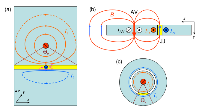
Let’s consider a single vortex in one electrode of a planar junction, as sketched in Fig. 1 (a). We assume that the junction is short, i.e., its length is smaller than double the Josephson penetration depth . The vortex has a phase rotation, clockwise circulating currents and magnetic flux, decaying at some characteristic scale . In the limiting cases of very thick films, , the decay length inside a superconducting electrode is equal to the London penetration depth, , and for very thin films, to the Pearl length Pearl_1964 . Finally, there are stray fields from the vortex outside electrodes. They can not enter superconducting electrodes and, therefore, stretch along the surface until the edges, where they eventually close, as sketched in Fig. 1 (b). In this section we discuss how do four vortex-related factors, i) phase rotation of the superconducting condensate, ii) circulating current, iii) inner field and iv) stray fields, contribute to the Josephson phase shift.
As reported earlier Golod_2010 , the value and the sign of AV-induced Josephson phase shift can be obtained using a naive assumption of a rigid phase rotation around the vortex (the London gauge). In this case the phase shift is just equal to the polar angle,
| (1) |
where is the vorticity (+1 for a vortex, -1 for an antivortex). Here is the coordinate of the vortex along the junction and is the distance to the junction. The total phase shift is equal to the polar angle of the vortex within the junction , indicated in Fig. 1 (a), . When vortex is close to the junction, , it induces a step-like shift, turning the junction into a state Golod_2010 ; Golod_2015 . The sign of the phase shift is determined by the direction of phase rotation. In Fig. 1 (a) we sketch the case of a vortex (clockwise rotation) in the top electrode. Since the Josephson phase is the difference in phases of top and bottom electrodes, a vortex induces a negative phase shift , irrespective in which electrode it is placed. Indeed, when it is placed in the top electrode, it induces a negative phase gradient solely in the top electrode. But if we translate it to the bottom electrode it will induce a positive phase gradient solely in the bottom electrode. This explains the minus sign and the absolute value in Eq. (1). However, as we already mentioned, rigid phase rotation can not be a proper explanation of the vortex-induces Josephson phase shift because in quantum mechanics the phase difference is determined only at a closed loop and can not acquire a physically significant value at an interval (junction length). Therefore, the phase shift has to be induced by circulating currents and fields of the vortex.
Current densities in the two electrodes are described by the generalized second London equation:
| (2) |
Here and are the corresponding scalar (phase) and vector potentials. The gauge-invariant Josephson phase difference is obtained by integration of Eq.(2) over an infinitesimal contour covering the barrier, 1-2-3-4 in Fig. 1 (a),
| (3) |
Here is the width of the barrier, are components of supercurrent densities in the vicinity of the barrier in electrodes 1 and 2, is the -component of magnetic induction in the barrier.
In the Meissner state, are obtained by solving Eq.(2) in the electrodes, with boundary conditions outside the junction, . Straightforward calculations yield Fluxon_1997 :
| (4) |
Here and . For a short junction screening within the junction is negligible, . This leads to proportionality of the phase gradient to the applied field. Integrating over the junction length provides a simple relation between the total phase shift within the junction and the flux:
| (5) |
Here is the total flux in the junction and is the effective magnetic thickness of the junction. For conventional overlap junctions for thick electrodes , and for thin electrodes , respectively. For planar junctions, studied below, is determined by the size of junction electrodes. Kogan2001 ; Mints2008 ; Clem2010 ; Boris_2013 ; Golod_2019
In the presence of AV the Josephson phase difference is a superposition of contributions from the Meissner state, , and vortex-induced phase shift at zero field, :
| (6) |
Currents and fields contribute differently to the phase shift. For example, in the mesoscopic case , the total flux carried by the vortex becomes negligible Fluxon_1997 . Thus, there is no magnetic field neither inside, nor outside the vortex and current makes the only contribution to the phase shift. All previous theoretical studies considered a similar case Aslamazov_1984 ; Gurevich_1994 ; Clem_2011 ; Kogan2014 ; Mironov_2017 . We note that junctions studied here and earlier Golod_2010 ; Golod_2015 have intermediate electrode thickness Boris_2013 and their sizes m are significantly larger that nm. Therefore, stray fields can not be neglected in the experiment. Below we consider limiting cases of both small and large junctions.
II.1 II A. Current induced phase shift in a mesoscopic limit
Let’s first consider the case of a very small junction with sizes . In this case the vortex does not carry flux and all magnetic field effects can be neglected. Then the London equation 2 can be rewritten in cylindrical () coordinates as
| (7) |
where is a delta-function. Direct integration yields
| (8) |
Since , there are no field-induced screening currents in the second electrode, . If we substitute Eq. (8) into Eq. (3), we obtain , which is equivalent to Eq. (1). However, this is not a self-consistent solution because Eq. (8) does not take into account boundary conditions at the edges of the electrode. The circulating current can not cross the edges Note0 . This leads to distortion of stream lines, as sketched in Fig. 1 (a).
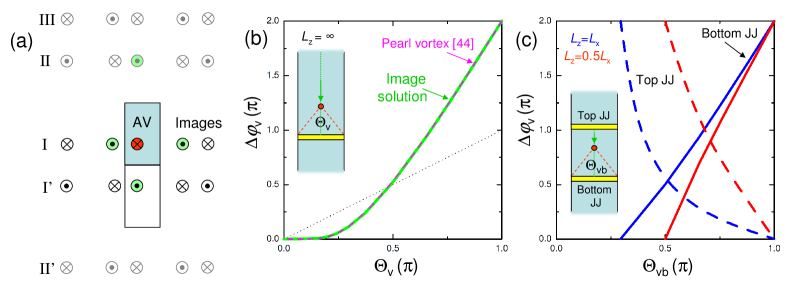
The boundary condition can be accounted for by using a well known image method Gurevich_1994 . A mirror image with opposite vorticity should be added at the opposing side from the edge so that it cancels out the perpendicular component of currents through this edge. However, it adds a smaller current at the opposite edge. To compensate for it we should introduce an image of an image at the opposing edge, and so on. This leads to an infinite series of images due to reflections from all the edges, as illustrated in Figure 2 (a). Each image vortex generates a phase shift according to Eq. (1) with image vortex coordinates and corresponding vorticity . The image solution for vortex-induced phase shift is then
| (9) |
Here the sum is taken over the image array. It is rapidly converging and can be easily calculated, as described in the Appendix A. For the case of semi-infinite electrode, , the image array consists of the primary image row-I due to reflections from left and right edges, and an anti-row I’ due to mirror reflection from the bottom (junction) edge, see Fig. 2 (a). The green line in Fig. 2 (b) shows the corresponding total antivortex induced phase shift as a function of the polar angle of the vortex within the junction , for a vortex in the middle of electrode .
In Ref.Clem_2011 J. Clem obtained a self-consistent solution for a Pearl- vortex-induced phase shift in a thin film planar Josephson junction with narrow long electrodes (, , ) using a conformal mapping method technique. The solution is described in Appendix B. It is shown by the dashed magenta line in Fig. 2 (b). Apparently it coincides with the image array solution. The coincidence is not occasional because in the considered flux-free mesoscopic case the only vortex feature is the delta-function phase singularity, Eq.(7), irrespective of the vortex type (Pearl or Abrikosov). Consequently, the solutions are also identical.
From Fig. 2 (b) it is seen that a vortex far away from the junction, , induces a negligible phase shift . Upon approaching the junction, the phase shift increases and reaches the maximum value when the vortex is at the edge of the junction, . The doubling of the phase shift with respect to the polar angle is due to concentration of current in the narrow gap between the vortex and the junction. It can be viewed as being due to an additional currents of the same sign from the image antivortex on the other side of the junction. This doubling is quite peculiar. The total phase shift around the vortex is always . However, at all of it is concentrated at one point at the nearest edge. This is, apparently, inconsistent with a naive picture of a rigid phase rotation around the vortex. Curiously, if we would make junctions at all the edges of vortex-carrying electrode, all other junctions except the one at which the vortex is placed would not show any phase shifts in this case. Below we will perform a similar experiment - simultaneous detection of the phase shift from different sides of the vortex. This, however, could be done only for a finite-size electrode. For a finite reflections from the top edge of the electrode leads to appearance of the top image anti-row II. Subsequent reflections from bottom and top edges lead to appearance of an infinite series of image rows I, I’, II, II’, III, e.t.c, as sketched in Fig. 2 (a) (see Appendix A for details).
Inset in Fig. 2 (c) shows a sketch of a double-junction experiment, which we will present below. In this case the vortex is placed in a rectangular electrode with two junction on top and bottom edges. Solid lines in Fig. 2 (c) show phase shifts in the bottom junction versus polar angle of the antivortex in the bottom junction for square (blue) and rectangular (red) electrodes. Dashed lines represent corresponding phase-shifts in the top junction. It can be seen that upon moving the antivortex from one junction to another the phase shift changes from to 0 in the former and from 0 to in the latter.
The uneven, not proportional to the polar angle, Eq. (1), variation of the phase shift is characteristic for the considered mesoscopic case and is associated with non-linearity (singularity) of current distribution around the vortex center, Eq.(8). Therefore, this disproportionality can be considered as a signature of the circulating current mechanism of vortex-induced Josephson phase shift. Finally, we note that although the phase shift from the vortex in this limit is determined by Eqs.(1,8) and decays in a long-range manner , this is not a long range phenomenon because it is valid only at . In principle, the image method can be extended to provided there are no stray fields Aslamazov_1984 ; Gurevich_1994 ; Mironov_2017 . This is the case for infinite-size objects with zero demagnetization factor. But we will not discuss it further because it is not relevant for the considered case of planar thin-film junctions Golod_2010 ; Golod_2015 and because this effect is rapidly decreasing at Aslamazov_1984 and becomes insignificant at longer scales.
II.2 II B. Stray-field effect in a large junction
Next we consider an opposite limit, , which is usually the case for Josephson junctions. Now the vortex carries the full flux quantum and magnetic field effects are essential. If vortex-junction distance is (much) larger than the effective penetration depth , we may neglect circulating vortex currents in the bulk of electrodes at the junction. In this case vortex stray fields become dominant due to a large demagnetization factor of planar junctions Golod_2019 . Fig. 1 (a) and (b) represent sketches of the top and side views of a planar junction with an Abrikosov vortex in electrode-1. Closed lines with arrows in (b) represent stray-field lines and in (a) streamlines of stray field-induced surface currents. Since stray fields can not enter the superconductor, they have to spread along the surface until the edge up to arbitrary long distance, thus creating truly long range phenomena, determined by electrode size, rather than . Distribution of long-range surface currents can be understood using the short-circuit principle: “In a complex system of superconducting films, if two neighboring film surfaces are short-circuited, it will not affect the current distribution in any other part of the system other than the two short-circuited surfaces” Schmidt . It means that at a long range current distribution in electrodes would be the same as if there were no junction. Therefore, outmost dashed current streamlines in the top and bottom electrodes in Fig. 1 (a) should complete the same circle.
When vortex stray field reach the junction, the corresponding fraction of the flux closes through the junction, as sketched in Fig. 1 (b). This creates an actual magnetic field in the junction with the sign opposite to that of the vortex. This field is large because of flux-focusing effect (large demagnetization factor) Golod_2019 . It induces correspondingly large edge currents in the junction banks, which have equal amplitudes but opposite directions, , as sketched in Figs. 1 (a,b). We want to emphasize the principle difference between circulating currents of the vortex, which are bulk (flow in the whole film thickness) and short-range , and stray-field induced surface currents, which are long range determined by the geometry of electrodes. In Fig. 1 (b) we tried to separate them by painting short-range bulk vortex currents in white and long-range stray-field-induced currents in orange/blue. In the limit considered here, , only stray-field-induced surface currents are present at the junction banks.
The phase shift, induced by the stray field is given by Eq. (5), where is the total stray flux closing through the junction. Since electrodes have a large area, , all the field reaching the junction goes in it because the penalty for stretching it further is too high. The stray flux can be calculated exactly for the Corbino disk electrode geometry, see Fig. 1 (c), with a junction being a segment of the circle (painted yellow). In this case, due to rotational symmetry the stray flux in the junction is
| (10) |
leading to the phase shift, given by the polar angle
| (11) |
consistent with Eq. (1).
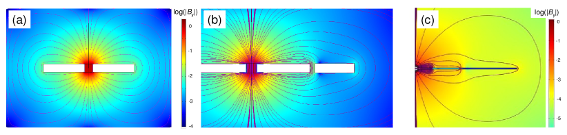
Finding distribution of currents and stray fields in realistic planar junctions with large demagnetization factors is a complex three-dimensional problem, which can be solved only numerically. Figure 3 represents corresponding simulations Note1 . We represent data in logarithmic scale so that color scales represent and densities of field lines . Fig. 3 (a) shows stray field distribution from a vortex in the middle of the square shape superconducting film. In Fig. 3 (b) additional electrode is added to the right of the initial electrode with the vortex. The gap between the two electrodes represents the junction. It is seen that upon reaching the junction the stray field is mostly penetrating into it and only a very small fraction reaches the right edge of the junction. A simulation in Fig. 3 (c) represents the case with a third wider electrode added to the right, thus forming two junctions. It can be seen that most of the stray field lines from the vortex are closed in the nearest junction and very few are expanding further out (note the logarithmic scale). The incomplete closing of stray fields in the nearest junction in presented simulations is a consequence of a too small demagnetization factor (scaling with ) that we had to adopt for making a reasonably coarse mesh, to solve the problem on a personal computer. Planar junctions, studied below have a much larger , with proportionally larger energetic penalty for stretching stray field lines to the outmost edge. Thus, from the 3D simulations, we anticipate that although the stray field could stretch to an arbitrary long distance along the electrode, it would be terminated by the first interruption junction.
We have checked that the stray flux and the phase shift in the junction indeed scales approximately proportionally to the polar angle , qualitatively consistent with Eq. (1). This indicates a uniform radial spreading of vortex stray-fields. Therefore, in the considered limit of a large junction and for the phase shift is induced solely by stray fields, proportionally to the polar-angle Eq. (1).
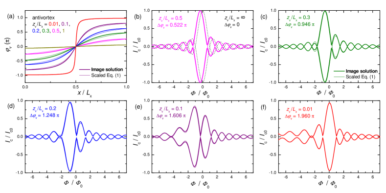
To summarize this section, there are two distinct contributions to vortex-induced Josephson phase shift: (i) A short-range circulating-current-induced mechanism with a phase shift determined by the image series solution, disproportional with respect to ; (ii) A long range stray field mechanism, proportional to . Despite quantitative differences, phase shifts for both mechanisms appear to be qualitatively similar and decay in a long-range manner as . This is demonstrated in Figure 4 (a), which shows vortex-induced phase shifts for the two mechanisms for an antivortex at different distances from a junction along the middle line of an infinitely long electrode . Thick lines represent an image solution (Eq. (13) from Appendix A, which coincides with the Pearl-vortex solution Eq. (14) from Appendix B). Thin lines represent the stray field contribution equal to the polar angle, Eq. (1), scaled to the same total phase shift. Apparently, the curves have similar shapes with only a minor difference at the edges due to different boundary conditions. The circulating current mechanism requires zero phase gradient at the edges because there is neither current through the edge, not magnetic flux in the corresponding mesoscopic limit. For the stray-field mechanism there is a finite field in the junction, which leads to a finite gradient at the edges, according to Eq. (4). Both effects are terminated at the junction because neither circulating currents nor stray fields would propagate beyond it. Therefore, the main difference and the only way to discriminate the two mechanisms are different values and functional dependence as seen from comparison of dotted black (stray field) and solid green (circulating current) lines in Fig. 2 (b). In the stray field case the maximal phase shift is equal to the maximal possible polar angle . However, in the circulating-current mechanism is nonlinear and can be doubled to .
II.3 II C. Numerical analysis of patterns
Appearance of vortex-induced phase shift in the junction leads to distortion of the modulation pattern Golod_2010 ; Clem_2011 ; Golod_2015 . In a short junction limit the distortion can be easily calculated by finding a maximum of Josephson current , integrated over the junction length, with given by Eq. (6). Successive distortion of patterns upon approaching the vortex to the junction for phase shifts from Fig. 4 (a) are shown in Figs. 4 (b-f). Thick and thin lines represent image solution and polar angle Eq.(1), scaled to the same total phase shift. It is seen that the difference between the two solutions is insignificant. Therefore, in the following we will use Eq. (1), with as a fitting parameter, for determination of vortex-induced phase shifts from experimental patterns.
III III. Experimental analysis
Planar proximity-coupled Josephson junctions (of SNS-type, S- superconductor, N- normal metal) are made by cutting N/S bi-layers by a Focused Ion Beam (FIB). The bi-layer is deposited by magnetron sputtering. Films are first patterned into m wide bridges by photolithography and ion etching and subsequently nano-patterned by FIB. Finally, a vortex trap (a hole with a diameter nm) is made by FIB. We used various N-metals: Cu, Fig. 5, a superparamagnetic CuNi alloy with approximately 50-50 concentration, Figs. 6, 7, and some other, all showing similar behavior. In all presented cases the thicknesses of N-layer (Cu or CuNi) is 50 nm and S-layer (Nb) is 70 nm. Measurements are done in a closed-cycle 4He cryostat. Magnetic field is applied perpendicular to the film. More details about fabrication and characterization of such planar junctions can be found in Refs. PhysicaC_2005 ; Anticorrelation_2007 ; Golod_2010 ; Boris_2013 ; Golod_2015 ; Golod_2019 .
To study the mechanism of vortex-induced Josephson phase shift we fabricated devices with vortex traps at different distances from junctions and, correspondingly with different polar angles . The vortex can be manipulated (introduced or erased) by magnetic field and bias current Golod_2010 ; Golod_2015 . We always start with the vortex-free state, obtained after zero-field cooling of the sample without bias current. A vortex is introduced in the trap by applying an appropriate current either at zero field or at small field below the lower critical field of the electrode, as described in Ref. Golod_2015 . Entrance/exit of AV results in an abrupt (instantaneous) change of the critical current. The two states with and without a vortex in the trap form steady and perfectly reproducible binary states Golod_2015 . This is how we can be sure that the vortex is indeed sitting in the trap. Only such reproducible states are shown and analyzed below. It could happen that eventually additional vortices enter junction electrodes and are placed randomly outside the trap. However this leads to irreversible and irreproducible states. If this happens, we clean the device by repeating the zero-field cooling procedure. For double-junction experiments, the position of the vortex can be unambiguously triangulated by simultaneous detection of responses of both junctions.
III.1 III A. Single junction experiment
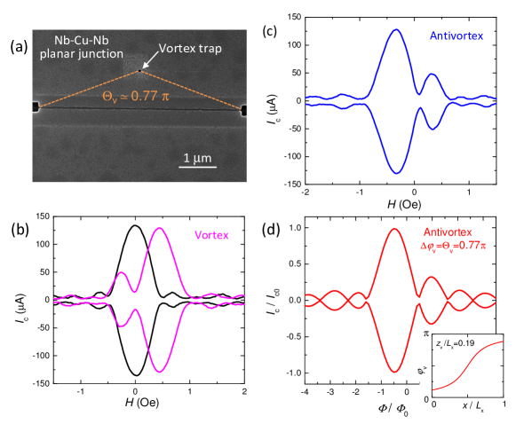
Fig. 5 (a) shows scanning electron microscope (SEM) image of a Nb-Cu-Nb planar junction with a vortex trap. The junction, shown in Fig. 5 (a) is made of Cu(50 nm)Nb(70 nm) bilayer. It has a length m. The vortex trap is placed in the middle of the top electrode at a distance m, corresponding to a polar angle . Black lines in Fig. 5 (b) represent measured modulation for this junction at K in the vortex-free state, obtained after zero-field cooling. It has a regular Fraunhofer-type modulation with a single central maximum at zero flux, .
Magenta lines in Fig. 5 (b) represent the measured pattern for the same junction after trapping a vortex in a positive field. Apparently, the is significantly distorted. The main maximum is shifted towards positive field and an additional secondary maximum appears at the left side. The shift of the main maximum in the direction of applied field is very characteristic for a trapped vortex Golod_2010 . Since the main maximum corresponds to , such a shift indicates that the effective vortex-induced field in the junction is reverse with respect to the applied field. I.e., in Fig. 5 (b) the vortex-induced flux is negative and a positive field is needed to compensate it to , leading to a corresponding shift of the main maximum . This is opposite to the pattern shift, which occurs in ferromagnetic junctions Iovan_2014 . This sign of the vortex-induced flux is expected for the stray-field, as sketched in Fig. 1 (b). Fig. 5 (c) shows measured pattern for the same junction with a trapped antivortex in a negative applied field. Apparently, it is mirror-reflected with respect to the vortex case, Fig. 5 (b).
In the case depicted in Fig. 5, the vortex is placed at a rather large distance m from the junction, which is significantly longer than both London, nm, and Pearl, nm, lengths. Therefore, as explained in sec. II B, vortex stray fields should make a dominant contribution to the Josephson phase shift and it should be . Fig. 5 (d) represents numerically calculated with the antivortex-induced phase shift according to Eq. (1) with experimental . Apparently, the simulation in Fig. 5 (d) is in a quantitative agreement with the experimental data in Fig. 5 (c) without any fitting. From such an analysis we conclude that the vortex-induced Josephson phase shift scales with the polar angle, , for large , consistent with earlier report Golod_2010 .
III.2 III B. Double junction experiment
As discussed in sec. II above, double junction experiment can provide a crucial information about the mechanism of vortex-induced phase shift. We made samples, containing two planar junctions and a vortex trap at different places. Double-junction devices have a cross-like geometry with four electrodes: top and bottom electrodes and left and right electrodes connected to the middle electrode between the junctions. Thus we can send the current through both junctions from bottom to top electrode and measure simultaneously characteristics of both junctions (for more details see Refs. Golod_2015 ; Golod_2019 ). Figures 6 (a) and (b) show vortex-free modulations measured simultaneously for two Nb-CuNi-Nb junctions at the same device at K. Both junctions exhibit regular Fraunhofer-like modulation , indicating good uniformity of the junctions Krasnov_1997 and reproducibility of the fabrication technique.
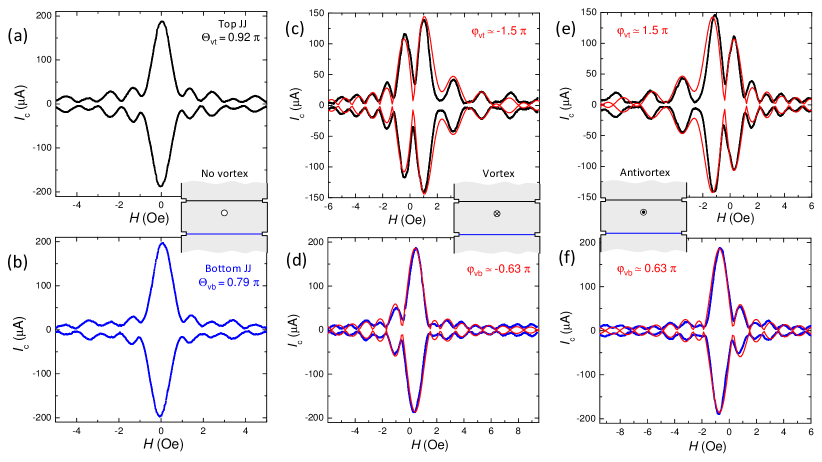
First we consider the case when a vortex trap is placed in the middle electrode, shared by both junctions, as sketched in the inset in Fig. 2 (c). For this device junction lengths are similar m and m and separation between junctions is m. The vortex trap is placed closer to the top junction, m, and m to the bottom junction, as sketched in the inset. Corresponding polar angles are and . In this case the vortex should simultaneously induce dissimilar phase shifts in both junctions, as shown in Fig. 2 (c).
Black and blue symbols in Figs. 6 (c) and (d) show measured patterns for top and bottom junctions, respectively, after trapping a vortex. Figs. 6 (e) and (f) show corresponding measurements with a trapped antivortex in negative field. Apparently, vortex, Figs. 6 (c,d), and antivortex, Figs. 6 (e,f), characteristics are mirror symmetric. From Fig. 6 it is obvious that a vortex in the middle electrode distorts patterns in both junctions, but the distortion is stronger in the top junction, which is closer to the vortex, consistent with simulations from Fig. 4. Thus, a double-junction geometry allows an unambiguous triangulation of the vortex position.
In order to obtain the value of we perform fitting of data, as described above. Red lines in Figs. 6 (c-f) represent such fits. From those we obtain , which has a significantly larger absolute value than and , with a smaller absolute value compared to . This is inline with calculations for a double-junction sample with mesoscopic rectangular electrode from Fig. 3 (c): when vortex is close to the top junction (small ) the phase shift is concentrated in the top junction and becomes larger than up to a factor two for . However, this is accompanied by the reduction in the furthermost bottom junction, compare dashed and solid lines in Fig. 3 (c), qualitatively consistent with our observation.
III.3 III C. The cutoff effect
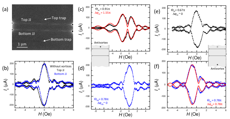
Next we’ll consider a specific case when the trap is placed in the outer electrodes. Figure 7 (a) shows a SEM picture of a double-junction device. Vortex-free characteristics for both junctions at K are shown in Fig. 7 (b). Junction lengths are m and m. In this sample we made junctions close to each other at a distance only m so that polar angles to both junctions are not very different. Initially, a single vortex trap was made in the top electrode close to the top junction, marked as the top trap in Fig. 7 (a). The corresponding distances to the top and the bottom junction are m and m, respectively, and polar angles are almost the same as in the case of Fig 6: and . However, the result of vortex trapping is quite different.
Figs. 7 (c) and (d) show patterns for the top and bottom junctions, respectively, with a trapped antivortex in the top trap at K. It is seen that in the top junction is strongly distorted. However, the bottom junction is practically unaffected by the vortex. Red lines in panel (c) represent a numerically simulated fit, which yields in the top junction, while in the bottom junction there is no visible distortion with respect to the vortex-free case . Apparently, the vortex in the top electrode does not induce a sensible phase shift in the bottom junction despite a quite large polar angle .
After this measurement the sample was taken back to FIB and a second bottom trap was made in the bottom electrode, marked in Fig. 7 (a), at the same distance and polar angle to the bottom junction as for the top trap, m, . Corresponding values for the top junction are m and . Figs. 7 (e) and (f) show modulation for top and bottom junctions with a trapped antivortex in the bottom trap. It is seen that in the bottom junction, which shares one electrode with the vortex, is now significantly distorted by the vortex at such a distance, while the top junction, which has vortex-free electrodes, is unaffected. A numerical fit, shown by red lines in Figs. 7 (f), yields , equal to the corresponding polar angle .
Observations from Fig. 7 clearly demonstrate that the vortex-induced Josephson phase shift is cutoff by the nearest junction and does not persist beyond it. In other words, the phase shift is induced only when the vortex is placed in one of the two junction electrodes and is not observed otherwise, irrespective of the distance between the vortex and the junction (for ). The cutoff effect makes it evident that this is not the Aharonov-Bohm effect that causes the phase shift. On the other hand, the cutoff is expected both for current and stray-field mechanisms, discussed in sec. II A and II B.
The current-induced phase shift cuts-off because the vortex current does not cross the junction, up to an accuracy given by the smallness of the Josephson current density compared to the circulating current density in the vortex . In the mesoscopic case, is very small, which ensures negligible vortex currents on the other side of the junction. At large distances circulating currents are small due to an exponential decay in case of an Abrikosov vortex or quadratic decay in case of a Pearl vortex Pearl_1964 , which leads to an effective cutoff at .
For the stray-field mechanism, the cutoff is caused by the energetic penalty of stretching the magnetic field lines beyond the nearest junction. It leads to almost complete closing of field lines through the nearest junction, as confirmed by numerical modelling in Fig. 3 (c).
III.4 III D. Distance dependence of the phase shift
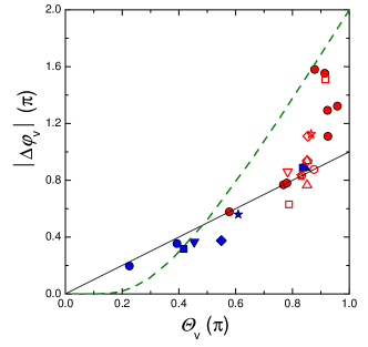
Figure 8 summarizes the dependence of observed phase shifts on the vortex polar angle. Blue symbols represent previously reported data from Ref. Golod_2010 . Red symbols represent new data from a variety of studied samples. Filled red symbols correspond to either single-junction samples, see Fig. 5, or double-junction samples with a vortex in outmost electrodes, see Fig. 7. Open red symbols represent double-junction data with a vortex in the middle common electrodes, as in Fig. 6. Here similar symbols represent phase shifts in the two junction on the same device. For example, open squares represent data from Fig. 6. The values are obtained from fitting using Eq. (1), as shown in Figs. 5-7. The accuracy of determination of is limited mostly by some deviations of vortex-free from the pure Fraunhofer pattern. It may also be affected by presence of far-away vortices (at ) that may create a small irregular distortion of , which is difficult to control just because of its smallness. We estimate the corresponding systematic uncertainty less than .
The straight black line represents the proportional to the polar angle dependence Eq. (1). The dashed green line represents the image solution for a long electrodes . From Fig. 8 it can be seen that for small angles (large distances) the vortex-induced Josephson phase shift scales with the polar angle , consistent with earlier report Golod_2010 . However at larger polar angles, corresponding to shorter distances nm, which is comparable to the estimated value of the Pearl length nm, the phase shift becomes larger than the polar angle and approaches the value, as predicted by the image solution Note2 . We can also see that some of the open red symbols lie below the line. Those points correspond to the farmost junctions in the double junction case with the vortex in the middle electrode, as in Figs. 6 (d,f). As we discussed in sec. II A, see Fig. 6 (c), such a deviation is expected for the current-induced mechanism in the mesoscopic (short-range) case due to concentration of the phase shift at the opposite junction, nearby the vortex.
The crossover from linear to superlinear behavior with decreasing the distance between the vortex and the junction is consistent with the theoretical analysis from sec. II and indicates a gradual transition from a long-range stray-field mechanism at large distances to a short-range circulating vortex current mechanism at . Thus we identify two distinct mechanisms of Josephson phase shift generation by an Abrikosov vortex. This is the main result of our work.
IV V. Conclusions
To summarize, we performed a systematic study of Abrikosov vortex-induced phase shift in planar Josephson junctions. We demonstrated that vortex induced Josephson phase shift depends on the polar angle of the vortex within the junction and decays slowly, in a long-range manner (non-exponentially), approximately inversely proportionally to the distance. Thus a significant phase shift can be generated even at very large distances (few microns), compared to the London penetration depth nm. However, experiments with two consecutive junctions have shown that vortex-induced phase shift is cutoff by the nearest junction and does not occur beyond it, irrespective of the distance. Thus, this is not a true long-range phenomenon, like the Aharonov-Bohm effect. The phase shift is induced only when the vortex is present in one of the junction electrodes. On a quantitative level we observed a crossover from a linear dependence at large distances to a superlinear dependence at shorter distances . To clarify the origin of vortex-induced phase shift we performed theoretical and numerical analysis of two mechanisms: circulating vortex currents at a short range and vortex stray-field at long range .
For the current-induced mechanism we derived a simple image array solution in the mesoscopic limit . In case of an infinitely long narrow electrode it coincides with the corresponding Clem’s solution for a Pearl vortex Clem_2011 . However, the image array solution is valid also for finite-size electrodes and both for Abrikosov and Pearl vortex. We emphasize, that the two phase-shift mechanisms are distinct and independent. The vortex stray field can spread to arbitrary long distances outside the superconducting film and can generate the phase shift at large distances where there are no circulating vortex currents the superconductor. Similarly, circulating vortex currents diverge with approaching the vortex center and create a large (up to ) phase shift only in the short-range , where circulating current densities are large. In the mesoscopic case it occurs without involvement of magnetic field. Observation of linear-to-superlinear crossover versus clearly demonstrates the gradual transition from one mechanism to another. Altogether this work provides a comprehensive quantitative description of the vortex induced Josephson phase shift. We anticipate that it can be employed for development of future generation of compact Josephson electronic devices like memory Golod_2015 and tunable phase shifters. Both the compactness and the tunability are facilitated by the small size of the Abrikosov vortex nm, which represent the smallest magnetic object in a superconductor.
Acknowledgements.
Acknowledgments: The work was accomplished during a visiting professor semester of VMK at the Moscow Institute of Physics and Technology and supported by the Russian Science Foundation, Grant No. 19-19-00594.Appendix A APPENDIX A: Calculation of a phase shift from a vortex-image array in the mesoscopic case
Lets consider a vortex () at position in the electrode-1 with sizes , as sketched in Fig. 2 (a). We assume that at least one of the sizes is small, . Mirror reflections from the vertical (left-right) edges will create a first image row (marked I in Fig. 2 (a)) at with anti-vortices at and and vortices at and . Each of them induces a phase shift according to Eq. (1). The original vortex will create a total phase shift . The two primary anti-vortex images (marked green in Fig. 2 (a)) will reduce it by . Subsequent vortex and antivortex pairs will add and , , correspondingly. As a result, the total phase shift induced by the row-I can be written as
| (12) |
If electrode-1 is semi-infinite , then we need to add only one additional image row from the bottom (junction) edge, marked I’ in Fig. 2 (a). It is obvious that this row will create exactly the same phase shift, as row-I. Consequently, for a semi-infinite electrode the total phase shift is double the phase shift of the primary row.
| (13) |
For a finite-size electrode additional image rows appear due to mirror reflections from the top edge, as depicted in Fig. 2 (a). Reflection of the primary row-I from the top edge leads to the secondary anti-row II . Its reflection from the bottom edge leads to a row II’ at , and so on. Each image vortex in the row generates a phase shift according to Eq. (1) with corresponding coordinates . Similar to the case of antivortices and vortices in the primary row I, antirows appear at and , rows at and and couples of rows are symmetric with respect to the junction (e.g. rows I - I’ and II - II’ in Fig. 2 (a)) and create identical phase shifts. This simplifies calculations.
The sum in Eq. (12) is well behaving and converges at , depending on . The larger is (small ) the more terms are needed. is enough for achieving an absolute accuracy . The simulated curves shown in Fig.2 (b) were obtained with 20 terms and absolute accuracy . For a finite , can not be small and, therefore, convergence is much faster. Data shown in Fig. 2 (a) for finite was obtained by summing four pairs of rows, but already three rows provide similar result with no visible difference at the scale of the graph.
Appendix B APPENDIX B: Comparison with the Pearl vortex solution in the mesoscopic case
For a thin film planar junctions with the thickness the effective screening length is given by the Pearl length Pearl_1964 , which expands the range of validity of the mesoscopic limit . In Ref. Clem_2011 Clem obtained a self-consistent solution for a phase shift induced by a Pearl vortex in a thin film planar Josephson junction with narrow, long electrodes using a conformal mapping method:
| (14) |
where , , and is a complex conjugate of . The solution is valid for a junction with , and . The dashed magenta line in Fig. 2 (b) shows corresponding Pearl-vortex induced Josephson phase shift. It coincides with the image solution for the half-infinite electrode , green line in Fig. 2 (b). As explained above the phase shift in this case is twice that for the primary image row I, see Fig. 2 (a) and Eqs. (12,13).
References
- (1) G. Blatter, V. B. Geshkenbein, and L. B. Ioffe, Design aspects of superconducting-phase quantum bits. Phys. Rev. B 63, 174511 (2001).
- (2) T. Ortlepp, Ariando, O. Mielke, C. J. M. Verwijs, K. F. K. Foo, H. Rogalla, F. H. Uhlmann, and H. Hilgenkamp, Flip-Flopping Fractional Flux Quanta. Science 312, 1495–1497 (2006).
- (3) A.K. Feofanov, et al., Implementation of superconductor/ferromagnet/superconductorpi-shifters in superconducting digital and quantum circuits. Nature Phys. 6, 593–597 (2010).
- (4) I. I. Soloviev, N. V. Klenov, S. V. Bakurskiy, M. Yu. Kupriyanov, A. L. Gudkov, and A. S. Sidorenko. Beyond Moore’s technologies: operation principles of a superconductor alternative. Beilstein J. Nanotechnol. 8, 2689-2710 (2017).
- (5) M. Neeley, M. Ansmann, R. C. Bialczak, M. Hofheinz, N. Katz, E. Lucero, A. O´Connell, H. Wang, A. N. Cleland, and J. M. Martinis, Transformed dissipation in superconducting quantum circuits. Phys. Rev. B 77, 180508(R) (2008).
- (6) S. Gladchenko, D. Olaya, E. Dupont-Ferrier, B. Douçot, L. B. Ioffe, and M. E. Gershenson, Superconducting nanocircuits for topologically protected qubits. Nature Phys. 5, 48–53 (2009).
- (7) J. B. Majer, J. B. Butcher, and J. E. Mooij, Simple phase bias for superconducting circuits. Appl. Phys. Lett. 80, 3638–3640 (2002).
- (8) M. Wulf, T. A. Ohki, and M. J. Feldman, A simple circuit to supply constant flux biases for superconducting quantum computing. J. Phys. Conf. Ser. 43, 1397–1400 (2006).
- (9) L. Longobardi, S. Pottorf, V. Patel, and J. E. Lukens, Development and Testing of a Persistent Flux Bias for Qubits. IEEE Trans. Appl. Supercond. 17, 88-89 (2007).
- (10) F. G. Paauw, A. Fedorov, C. J. P. M. Harmans, and J. E. Mooij, Tuning the Gap of a Superconducting Flux Qubit. Phys. Rev. Lett. 102, 090501 (2009).
- (11) X. Zhu, A. Kemp, S. Saito, and K. Semba, Coherent operation of a gap-tunable flux qubit. Appl. Phys. Lett. 97, 102503 (2010).
- (12) A. Fedorov, P. Macha, A. K. Feofanov, C. J. P. M. Harmans, and J. E. Mooij, Tuned Transition from Quantum to Classical for Macroscopic Quantum States. Phys. Rev. Lett. 106, 170404 (2011).
- (13) M. J. Schwarz, J. Goetz, Z. Jiang, T. Niemczyk, F. Deppe, A. Marx, and R. Gross, Gradiometric flux qubits with a tunable gap. New J. Phys. 15, 045001 (2013).
- (14) H. Deng, Y. Wu, Y. Zheng, N. Akhtar, J. Fan, X. Zhu, J. Li, Y. Jin, and D. Zheng, Working Point Adjustable DC-SQUID for the Readout of Gap Tunable Flux Qubit. IEEE Trans. Appl. Supercond. 25, 1602504 (2015).
- (15) D. Balashov, B. Dimov, M. Khabipov, T. Ortlepp, D. Hagedorn, A. B. Zorin, F.-I. Buchholz, F. H. Uhlmann, and J. Niemeyer, Passive Phase Shifter for Superconducting Josephson Circuits. IEEE Trans. Appl. Supercond. 17, 142-145 (2007).
- (16) B. Dimov, D. Balashov, M. Khabipov, T. Ortlepp, F.-I. Buchholz, A. B. Zorin, J. Niemeyer and F. H. Uhlmann, Implementation of superconductive passive phase shifters in high-speed integrated RSFQ digital circuits. Supercond. Sci. Technol. 21, 045007 (2008).
- (17) T. Golod, A. Iovan, and V. M. Krasnov. Single Abrikosov vortices as quantized information bits. Nature Commun. 6, 8628 (2015).
- (18) S. V. Bakurskiy, N. V. Klenov, I. I. Soloviev, M. Yu. Kupriyanov, and A. A. Golubov. Superconducting phase domains for memory applications. Appl. Phys. Lett. 108, 042602 (2016).
- (19) V. I. Zdravkov, D. Lenk, R. Morari, A. Ullrich, G. Obermeier, C. Müller, H.-A. Krug von Nidda, A. S. Sidorenko, S. Horn, R. Tidecks, and L. R. Tagirov. Memory effect and triplet pairing generation in the superconducting exchange biased Co/CoOx/Cu41Ni59/Nb/Cu41Ni59 layered heterostructure. Appl. Phys. Lett. 103, 062604 (2013).
- (20) E. Goldobin, H. Sickinger, M. Weides, N. Ruppelt, H. Kohlstedt, R. Kleiner, and D. Koelle. Memory cell based on a Josephson junction. Appl. Phys. Lett. 102, 242602 (2013).
- (21) B. Baek, W.H. Rippard, S.P. Benz, S.E. Russek, and P.D. Dresselhaus. Hybrid superconducting-magnetic memory device using competing order parameters. Nat. Commun. 5, 3888 (2014).
- (22) B. M. Niedzielski, T. J. Bertus, J. A. Glick, R. Loloee, W. P. Pratt, Jr., and N. O. Birge. Spin-valve Josephson junctions for cryogenic memory. Phys. Rev. B 97, 024517 (2018).
- (23) R. Fehrenbacher, V. B. Geshkenbein and G. Blatter. Pinning phenomena and critical currents in disordered long Josephson junctions, Phys. Rev. B 45, 5450-5467 (1992).
- (24) V.M. Krasnov, V.A. Oboznov, and N.F. Pedersen. Fluxon dynamics in long Josephson junctions in the presence of a temperature gradient or spatial nonuniformity. Phys. Rev. B 55, 14486–14498 (1997).
- (25) T. Gaber, E. Goldobin, A. Sterck, R. Kleiner, D. Koelle, M. Siegel and M. Neuhaus. Nonideal artificial phase discontinuity in long Josephson - junctions, Phys. Rev. B 72, 054522 (2005).
- (26) M. Alidoust and J. Linder. -state and inverted Fraunhofer pattern in nonaligned Josephson junctions, Phys. Rev. B 87, 060503 (2013).
- (27) T. Golod, O.M. Kapran, and V.M. Krasnov. Planar Superconductor-Ferromagnet-Superconductor Josephson Junctions as Scanning-Probe Sensors. Phys. Rev. Appl. 11, 014062 (2019).
- (28) B. Chesca, D. John, R. Pollett, M. Gaifullin, J. Cox, C. J. Mellor, and S. Savel’ev. Magnetic field tunable vortex diode made of YBa2Cu3O7-δ Josephson junction asymmetrical arrays, Appl. Phys. Lett. 111, 062602 (2017).
- (29) V.V. Ryazanov, V. A. Oboznov, A.Yu. Rusanov, A.V. Veretennikov, A. A. Golubov, and J. Aarts, Coupling of Two Superconductors through a Ferromagnet: Evidence for a Junction. Phys. Rev. Lett. 86, 2427-2430 (2001).
- (30) T. Kontos, M. Aprili, J. Lesueur, F. Genet, B. Stephanidis, and R. Boursier, Josephson Junction through a Thin Ferromagnetic Layer: Negative Coupling. Phys. Rev. Lett. 89, 137007 (2002).
- (31) H. Sellier, C. Baraduc, F. Lefloch, and R. Calemczuk1, Half-Integer Shapiro Steps at the 0- Crossover of a Ferromagnetic Josephson Junction. Phys. Rev. Lett. 92, 257005 (2004).
- (32) D. J. Van Harlingen, Phase-sensitive tests of the symmetry of the pairing state in the high-temperature superconductors: Evidence for symmetry. Rev. Mod. Phys. 67, 515-535 (1995).
- (33) C. C. Tsuei, and J. R. Kirtley, Pairing symmetry in cuprate superconductors. Rev. Mod. Phys. 72, 969-1016 (2000).
- (34) Y. Ota, M. Machida, T. Koyama, and H. Matsumoto. Theory of Heterotic Superconductor-Insulator-Superconductor Josephson Junctions between Single- and Multiple-Gap Superconductors, Phys. Rev. Lett. 102, 237003 (2009).
- (35) J. Linder, I.B. Sperstad, and A. Sudbø. phase shifts in Josephson junctions as a signature for the -wave pairing state, Phys. Rev. B 80, 020503(R) (2009).
- (36) A. E. Koshelev, Phase diagram of Josephson junction between and superconductors in the dirty limit. Phys. Rev. B 86, 214502 (2012).
- (37) A. A. Kalenyuk, A. Pagliero, E. A. Borodianskyi, A. A. Kordyuk, and V. M. Krasnov, Phase-Sensitive Evidence for the Sign-Reversal Symmetry of the Order Parameter in an Iron-Pnictide Superconductor Using Nb/Ba1-xNaxFe2As2 Josephson Junctions. Phys. Rev. Lett. 120, 067001 (2018).
- (38) A. Buzdin and A. E. Koshelev. Periodic alternating - and -junction structures as realization of -Josephson junctions, Phys. Rev. B 67, 229504(R) (2003).
- (39) H. Sickinger, A. Lipman, M. Weides, R. G. Mints, H. Kohlstedt, D. Koelle, R. Kleiner, and E. Goldobin. Experimental Evidence of a Josephson Junction, Phys. Rev. Lett. 109, 107002 (2012).
- (40) F. Konschelle, I. V. Tokatly, and F. S. Bergeret. Theory of the spin-galvanic effect and the anomalous phase shift in superconductors and Josephson junctions with intrinsic spin-orbit coupling, Phys. Rev. B 92, 125443 (2015).
- (41) L. G. Aslamazov and E.V. Gurovich, Pinning of solitons by Abrikosov vortices in distributed Josephson junctions. JETP Lett. 40, 746 (1984).
- (42) A. Gurevich and L. D. Cooley, Anisotropic flux pinning in a network of planar defects. Phys. Rev. B 50, 13563 (1994).
- (43) T. Golod, A. Rydh, and V.M. Krasnov. Detection of the Phase Shift from a Single Abrikosov Vortex. Phys. Rev. Lett. 104, 227003 (2010).
- (44) J. R. Clem, Effect of nearby Pearl vortices upon the Ic versus B characteristics of planar Josephson junctions in thin and narrow superconducting strips. Phys. Rev. B 84, 134502 (2011).
- (45) V.G. Kogan,and R.G. Mints. Interaction of Josephson junction and distant vortex in narrow thin-film superconducting strips. Phys. Rev. B 89, 014516 (2014).
- (46) S. Mironov, E. Goldobin, D. Koelle, R. Kleiner, Ph. Tamarat, B. Lounis, and A. Buzdin. Anomalous Josephson effect controlled by an Abrikosov vortex. Phys. Rev. B 96, 214515 (2017).
- (47) M.V. Miloc̆sević, A. Kanda, S. Hatsumi, F.M. Peeters, and Y. Ootuka, Local current injection into mesoscopic superconductors for the manipulation of quantum states. Phys. Rev. Lett. 103, 217003 (2009).
- (48) J. Sok and D. K. Finnemore, Thermal depinning of a single superconducting vortex in Nb. Phys. Rev. B 50, 12770-12773 (1994).
- (49) I.S. Veshchunov, W. Magrini, S.V. Mironov, A.G. Godin, J.-B. Trebbia, A.I. Buzdin, Ph. Tamarat, and B. Lounis. Optical manipulation of single flux quanta. Nature Commun. 7, 12801 (2016).
- (50) Y. Aharonov and D. Bohm. Significance of Electromagnetic Potentials in the Quantum Theory. Phys. Rev. 115, 485-491 (1959).
- (51) J. Pearl. Current distribution in superconducting films carrying quantized fluxoids. Appl. Phys. Lett. 5, 65-66 (1964).
- (52) V. M. Krasnov and D. Winkler, Static and dynamic properties of stacked Josephson junctions: Analytic solution. Phys. Rev. B 56, 9106 (1997).
- (53) A. A. Boris, A. Rydh, T. Golod, H. Motzkau, A. M. Klushin, and V. M. Krasnov. Evidence for Nonlocal Electrodynamics in Planar Josephson Junctions. Phys. Rev. Lett. 111, 117002 (2013).
- (54) V.G. Kogan, V.V. Dobrovitski, J.R. Clem, Y. Mawatari, and R.G. Mints. Josephson junction in a thin film. Phys. Rev. B 63, 144501 (2001).
- (55) M. Moshe, V.G. Kogan, and R.G. Mints. Edge-type Josephson junctions in narrow thin-film strips. Phys. Rev. B 78, 020510(R) (2008).
- (56) J.R. Clem. Josephson junctions in thin and narrow rectangular superconducting strips. Phys. Rev. B 81, 144515 (2010).
- (57) We assume that the Josephson current density is negligible with respect to the circulating current density , which is easily satisfied in the considered limit due to divergence of Eq. (8) in the vortex center.
- (58) V. V. Schmidt, The Physics of Superconductors, Introduction to Fundamentals and Applications (Eds. P. Müller and A.V. Ustinov). Springer-Verlag 1997, ISBN 3-540-61243-2.
- (59) 3D numerical simulations are performed using the commercial software COMSOL Multiphysics. Superconductor is modelled as a material with zero magnetic permeability.
- (60) V.M. Krasnov, O. Ericsson, S. Intiso, P. Delsing, V.A. Oboznov, A.S. Prokofiev, and V.V. Ryazanov. Planar S-F-S Josephson junctions made by focused ion beam etching. Physica C 418, 16–22 (2005).
- (61) V. M. Krasnov, T. Golods, T. Bauch, and P. Delsing. Anticorrelation between temperature and fluctuations of the switching current in moderately damped Josephson junctions. Phys. Rev. B 76, 224517 (2007).
- (62) A. Iovan, T. Golod, and V. M. Krasnov. Controllable generation of a spin-triplet supercurrent in a Josephson spin valve. Phys. Rev. B 90, 134514 (2014).
- (63) For nm we were not able to reproducibly place a vortex in the trap, most likely because the attractive force to the junction edge (the antivortex image) exceeds the pinning force. This is not surprising because the current density at the distance from the vortex is a significant fraction of the depairing current and may well exceed the depinning current density from the trap.